Design Report
VerifiedAdded on 2023/01/10
|17
|798
|40
AI Summary
The report reflects the system design of Sunshine Motors, including the architecture, interface design, UML diagrams, and more.
Contribute Materials
Your contribution can guide someone’s learning journey. Share your
documents today.
Running head: DESIGN REPORT
Design Report
Name of the Student
Name of the University
Author’s Note:
Design Report
Name of the Student
Name of the University
Author’s Note:
Secure Best Marks with AI Grader
Need help grading? Try our AI Grader for instant feedback on your assignments.
1DESIGN REPORT
Executive Summary
The report reflects the system design of Sunshine Motors. The report includes the architecture of
the system based on which the entire system will work. The system interface shows how the
input/output screen of the system. The UML diagrams shows both the static and dynamic nature
of the system.
2DESIGN REPORT
Table of Contents
Architectural Design:.......................................................................................................................3
Hardware Specification:..................................................................................................................3
Class Diagram:.................................................................................................................................4
Interface Design:..............................................................................................................................5
Business Process Models:................................................................................................................8
Sequence Diagram:........................................................................................................................11
Interaction Diagram:......................................................................................................................13
State Diagram:...............................................................................................................................14
Bibliography:.................................................................................................................................16
3DESIGN REPORT
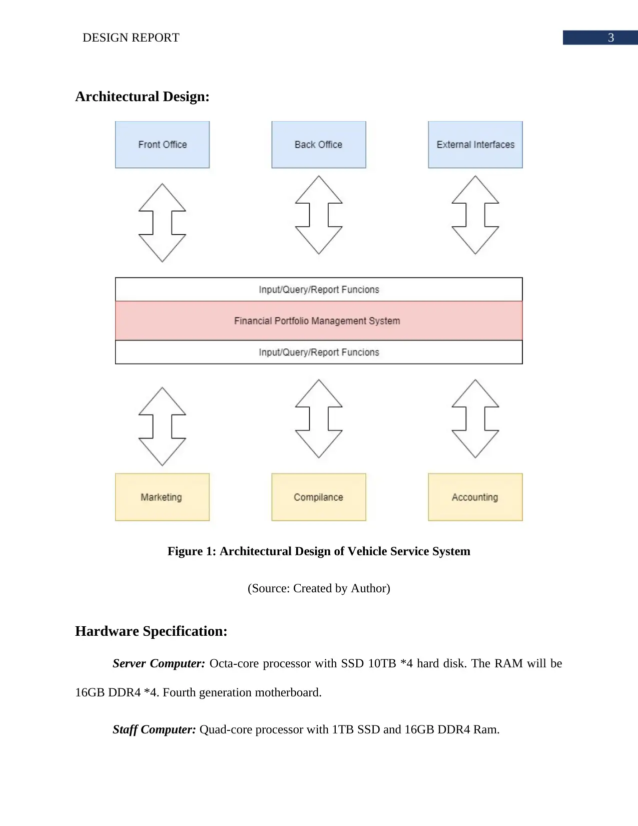
Architectural Design:
Figure 1: Architectural Design of Vehicle Service System
(Source: Created by Author)
Hardware Specification:
Server Computer: Octa-core processor with SSD 10TB *4 hard disk. The RAM will be
16GB DDR4 *4. Fourth generation motherboard.
Staff Computer: Quad-core processor with 1TB SSD and 16GB DDR4 Ram.
Secure Best Marks with AI Grader
Need help grading? Try our AI Grader for instant feedback on your assignments.
4DESIGN REPORT
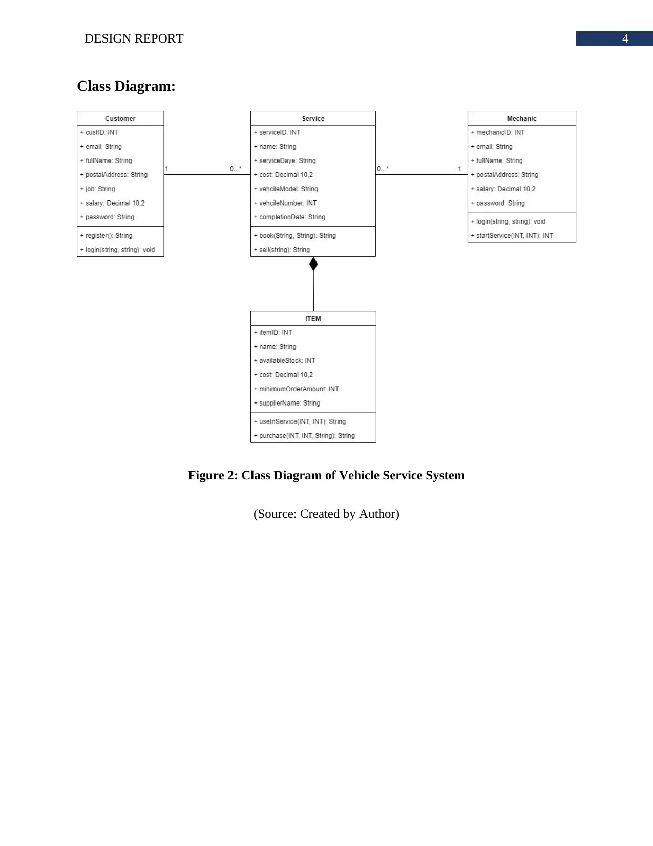
Class Diagram:
Figure 2: Class Diagram of Vehicle Service System
(Source: Created by Author)
Class Diagram:
Figure 2: Class Diagram of Vehicle Service System
(Source: Created by Author)
5DESIGN REPORT
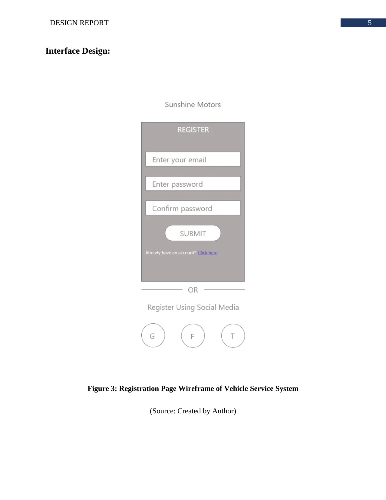
Interface Design:
Figure 3: Registration Page Wireframe of Vehicle Service System
(Source: Created by Author)
Interface Design:
Figure 3: Registration Page Wireframe of Vehicle Service System
(Source: Created by Author)
6DESIGN REPORT
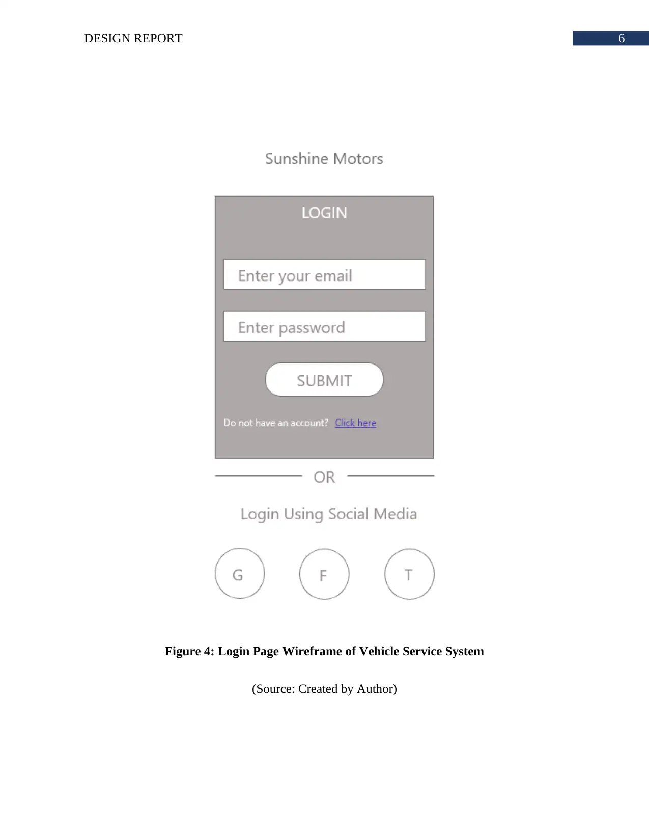
Figure 4: Login Page Wireframe of Vehicle Service System
(Source: Created by Author)
Figure 4: Login Page Wireframe of Vehicle Service System
(Source: Created by Author)
Paraphrase This Document
Need a fresh take? Get an instant paraphrase of this document with our AI Paraphraser
7DESIGN REPORT
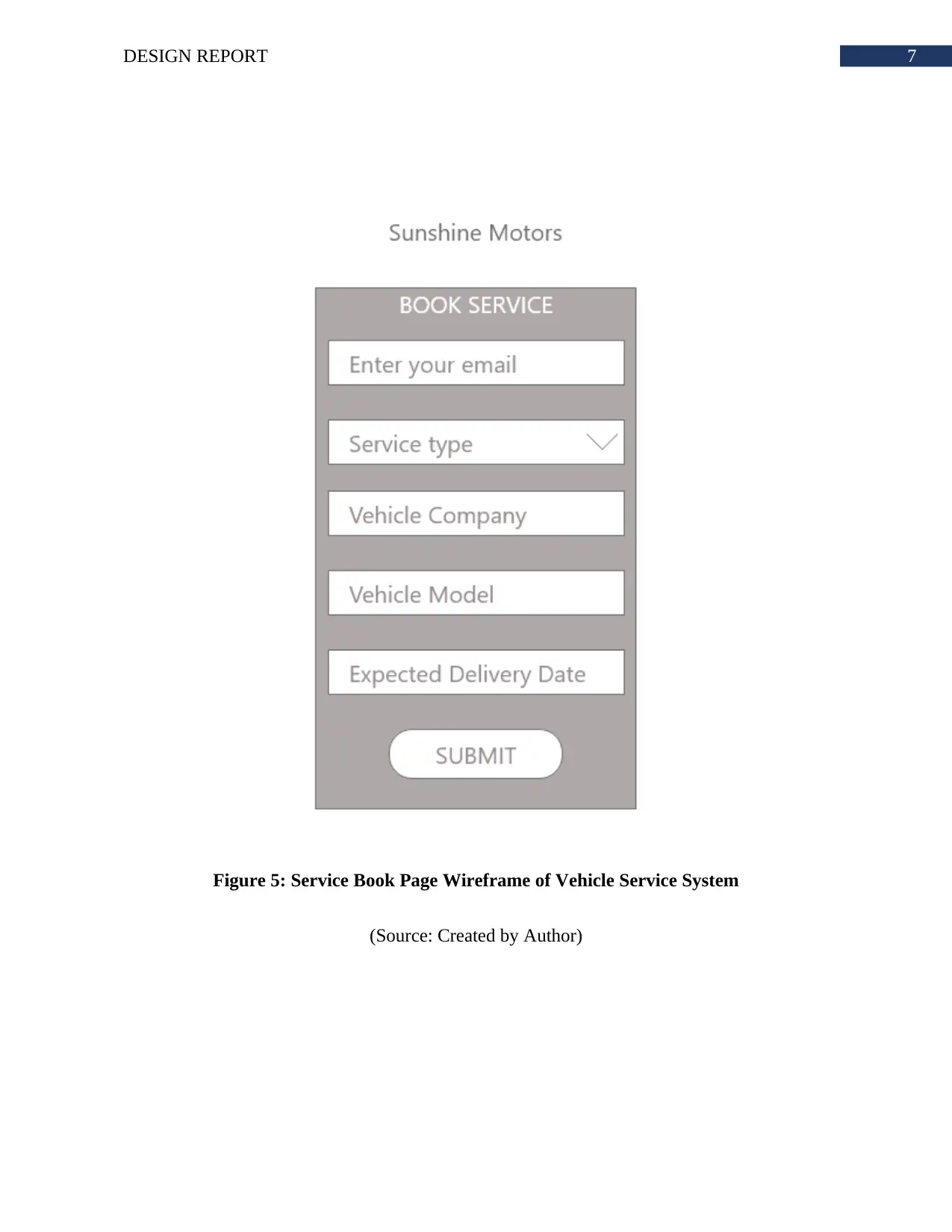
Figure 5: Service Book Page Wireframe of Vehicle Service System
(Source: Created by Author)
Figure 5: Service Book Page Wireframe of Vehicle Service System
(Source: Created by Author)
8DESIGN REPORT
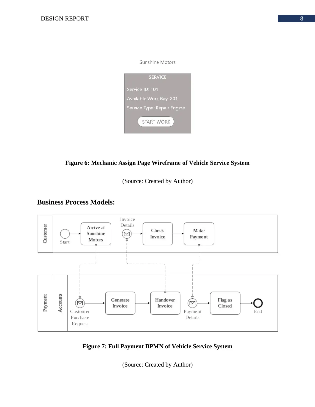
Figure 6: Mechanic Assign Page Wireframe of Vehicle Service System
(Source: Created by Author)
Business Process Models:
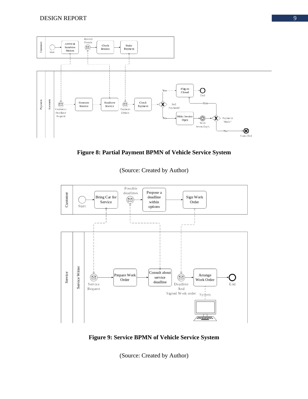
Figure 7: Full Payment BPMN of Vehicle Service System
(Source: Created by Author)
Figure 6: Mechanic Assign Page Wireframe of Vehicle Service System
(Source: Created by Author)
Business Process Models:
Figure 7: Full Payment BPMN of Vehicle Service System
(Source: Created by Author)
9DESIGN REPORT
Figure 8: Partial Payment BPMN of Vehicle Service System
(Source: Created by Author)
Figure 9: Service BPMN of Vehicle Service System
(Source: Created by Author)
Figure 8: Partial Payment BPMN of Vehicle Service System
(Source: Created by Author)
Figure 9: Service BPMN of Vehicle Service System
(Source: Created by Author)
Secure Best Marks with AI Grader
Need help grading? Try our AI Grader for instant feedback on your assignments.
10DESIGN REPORT
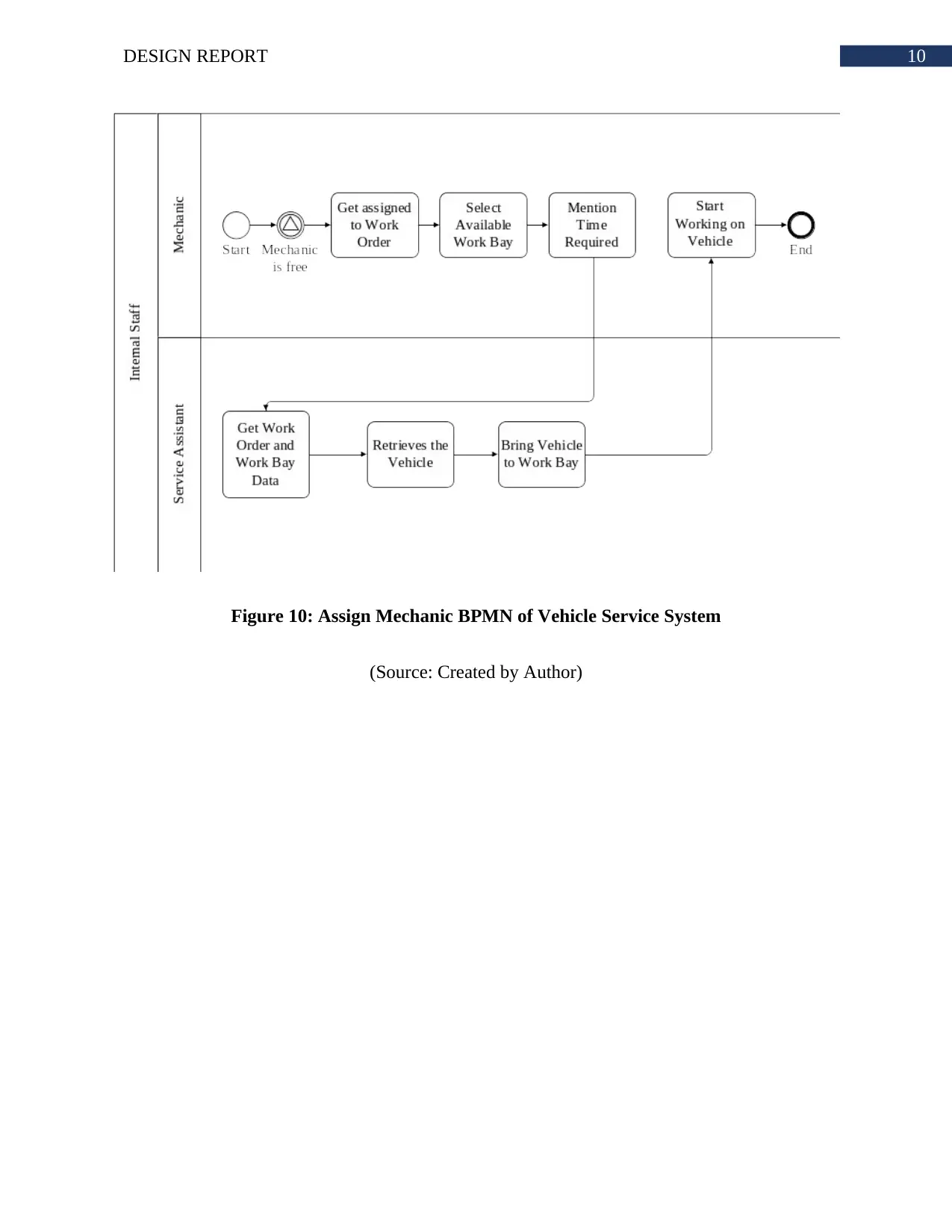
Figure 10: Assign Mechanic BPMN of Vehicle Service System
(Source: Created by Author)
Figure 10: Assign Mechanic BPMN of Vehicle Service System
(Source: Created by Author)
11DESIGN REPORT
Sequence Diagram:
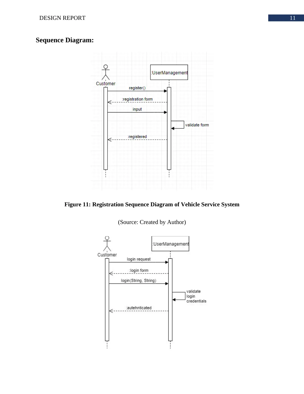
Figure 11: Registration Sequence Diagram of Vehicle Service System
(Source: Created by Author)
Sequence Diagram:
Figure 11: Registration Sequence Diagram of Vehicle Service System
(Source: Created by Author)
12DESIGN REPORT
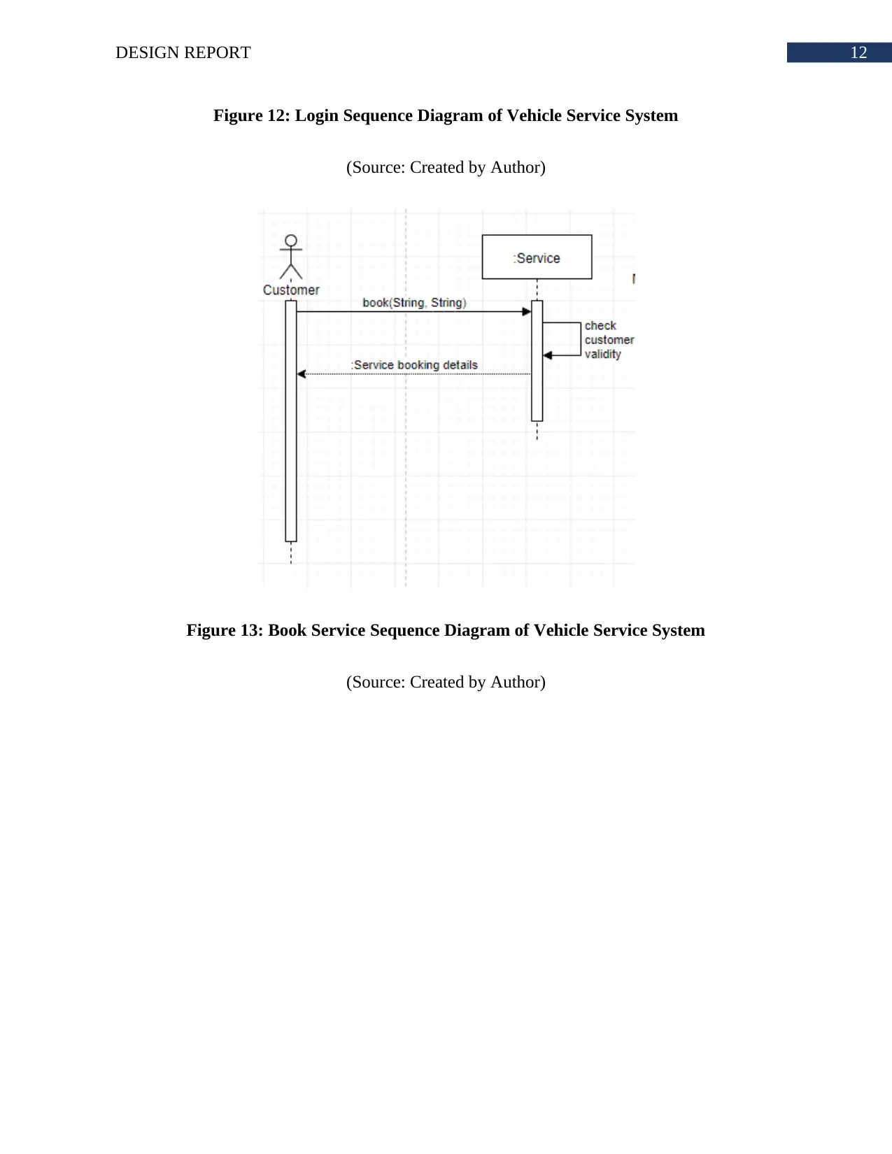
Figure 12: Login Sequence Diagram of Vehicle Service System
(Source: Created by Author)
Figure 13: Book Service Sequence Diagram of Vehicle Service System
(Source: Created by Author)
Figure 12: Login Sequence Diagram of Vehicle Service System
(Source: Created by Author)
Figure 13: Book Service Sequence Diagram of Vehicle Service System
(Source: Created by Author)
Paraphrase This Document
Need a fresh take? Get an instant paraphrase of this document with our AI Paraphraser
13DESIGN REPORT
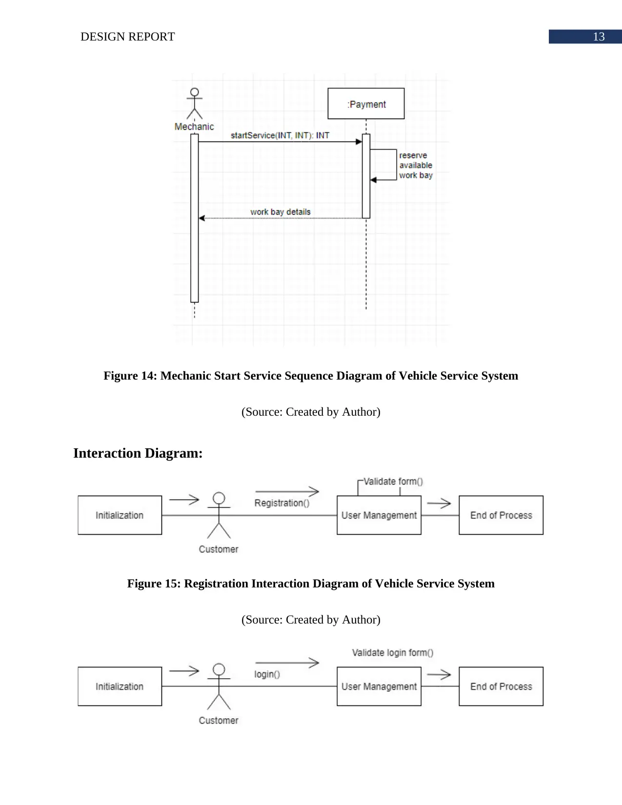
Figure 14: Mechanic Start Service Sequence Diagram of Vehicle Service System
(Source: Created by Author)
Interaction Diagram:
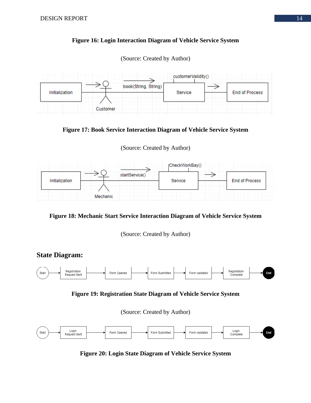
Figure 15: Registration Interaction Diagram of Vehicle Service System
(Source: Created by Author)
Figure 14: Mechanic Start Service Sequence Diagram of Vehicle Service System
(Source: Created by Author)
Interaction Diagram:
Figure 15: Registration Interaction Diagram of Vehicle Service System
(Source: Created by Author)
14DESIGN REPORT
Figure 16: Login Interaction Diagram of Vehicle Service System
(Source: Created by Author)
Figure 17: Book Service Interaction Diagram of Vehicle Service System
(Source: Created by Author)
Figure 18: Mechanic Start Service Interaction Diagram of Vehicle Service System
(Source: Created by Author)
State Diagram:
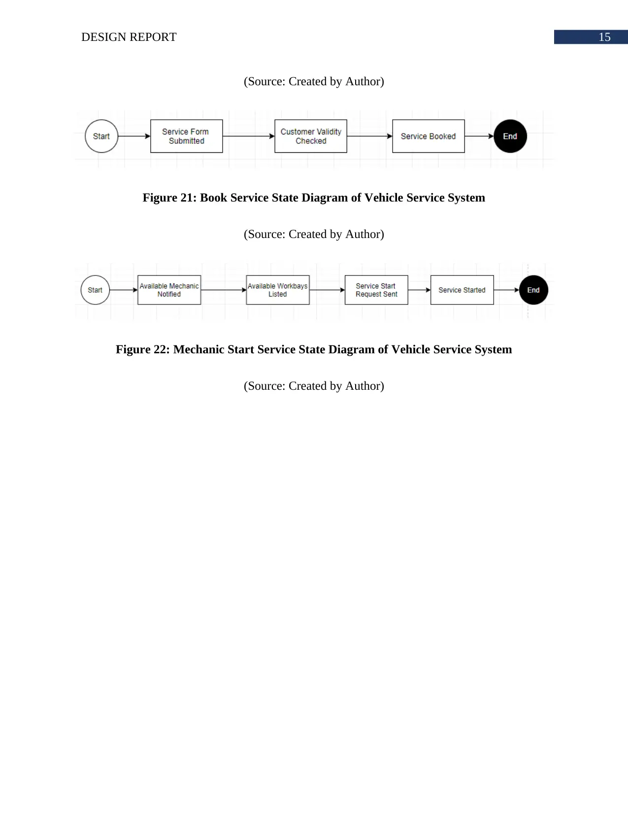
Figure 19: Registration State Diagram of Vehicle Service System
(Source: Created by Author)
Figure 20: Login State Diagram of Vehicle Service System
15DESIGN REPORT
(Source: Created by Author)
Figure 21: Book Service State Diagram of Vehicle Service System
(Source: Created by Author)
Figure 22: Mechanic Start Service State Diagram of Vehicle Service System
(Source: Created by Author)
(Source: Created by Author)
Figure 21: Book Service State Diagram of Vehicle Service System
(Source: Created by Author)
Figure 22: Mechanic Start Service State Diagram of Vehicle Service System
(Source: Created by Author)
Secure Best Marks with AI Grader
Need help grading? Try our AI Grader for instant feedback on your assignments.
16DESIGN REPORT
Bibliography:
Benselim, M.S. and Seridi-Bouchelaghem, H., 2017. Towards A UML Profile for Context-
Awareness Domain. International Arab Journal of Information Technology (IAJIT), 14(2).
Elallaoui, M., Nafil, K. and Touahni, R., 2018. Automatic transformation of user stories into
UML use case diagrams using NLP techniques. Procedia computer science, 130, pp.42-49.
Hendini, A., 2016. Pemodelan Uml Sistem Informasi Monitoring Penjualan Dan Stok Barang
(Studi Kasus: Distro Zhezha Pontianak). Jurnal Khatulistiwa Informatika, 4(2).
Rathee, N. and Chhillar, R.S., 2017. A survey on test case generation techniques using UML
diagrams. JSW, 12(8), pp.643-648.
Wautelet, Y. and Poelmans, S., 2017, November. An Integrated Enterprise Modeling Framework
Using the RUP/UML Business Use-Case Model and BPMN. In IFIP Working Conference on
The Practice of Enterprise Modeling(pp. 299-315). Springer, Cham.
1 out of 17
Related Documents
Your All-in-One AI-Powered Toolkit for Academic Success.
+13062052269
info@desklib.com
Available 24*7 on WhatsApp / Email
![[object Object]](/_next/static/media/star-bottom.7253800d.svg)
Unlock your academic potential
© 2024 | Zucol Services PVT LTD | All rights reserved.


