Network Design, Configuration and Security Report - University Name
VerifiedAdded on 2021/05/30
|15
|1626
|36
Report
AI Summary
This report details the configuration of a network, simulated using Packet Tracer, focusing on IP addressing, routing, and client access to services. The network topology consists of two routers, two servers (one acting as a DNS and DHCP server) and a client PC. The report provides a comprehensive guide to configuring IP addresses for all devices, setting up routing between routers, and enabling communication between devices. It also covers DHCP configuration on a server to assign IP addresses to clients, and web server setup with a DNS server. Furthermore, the report discusses enhancing network security through firewall configuration, specifically blocking TCP traffic between the client PC and web servers using access control lists, and includes references to industry-standard resources.
EXECUTIVE SUMMARY
For a network to work efficiently all devices in the network must be configured efficiently and
approprately to ensure 100% in communication. This report covers majorly on Ip addressing, routing and
how clients can access services from the servers. My report has a network topology that was simulated
using the packet tracer software. The topology has two routers and 3 end devices. Two servers and one
client PC. This report gives details of how I configured the Ip addresses for all the devices in the network
and also how I configured routing in the network and between the two routers. The report shows how
the devices can communicate with each other with ease and without any barriers. Also this report
details how you can configure client devices to get services from the servers i.e. web service and DHCP.
The DHCP assigns Ip addresses to devices on the network. I configured DHCP on one of the servers
which was able to provide IP address to the client machine. Finally this report details how you vcan
enhance security on your network by allowing and denying certain protocols on the network or denying
certain devices from communicating within the network
Paraphrase This Document
Need a fresh take? Get an instant paraphrase of this document with our AI Paraphraser
MY NETWORK LAYOUT
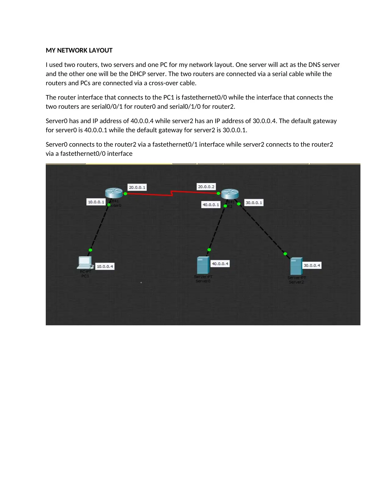
I used two routers, two servers and one PC for my network layout. One server will act as the DNS server
and the other one will be the DHCP server. The two routers are connected via a serial cable while the
routers and PCs are connected via a cross-over cable.
The router interface that connects to the PC1 is fastethernet0/0 while the interface that connects the
two routers are serial0/0/1 for router0 and serial0/1/0 for router2.
Server0 has and IP address of 40.0.0.4 while server2 has an IP address of 30.0.0.4. The default gateway
for server0 is 40.0.0.1 while the default gateway for server2 is 30.0.0.1.
Server0 connects to the router2 via a fastethernet0/1 interface while server2 connects to the router2
via a fastethernet0/0 interface
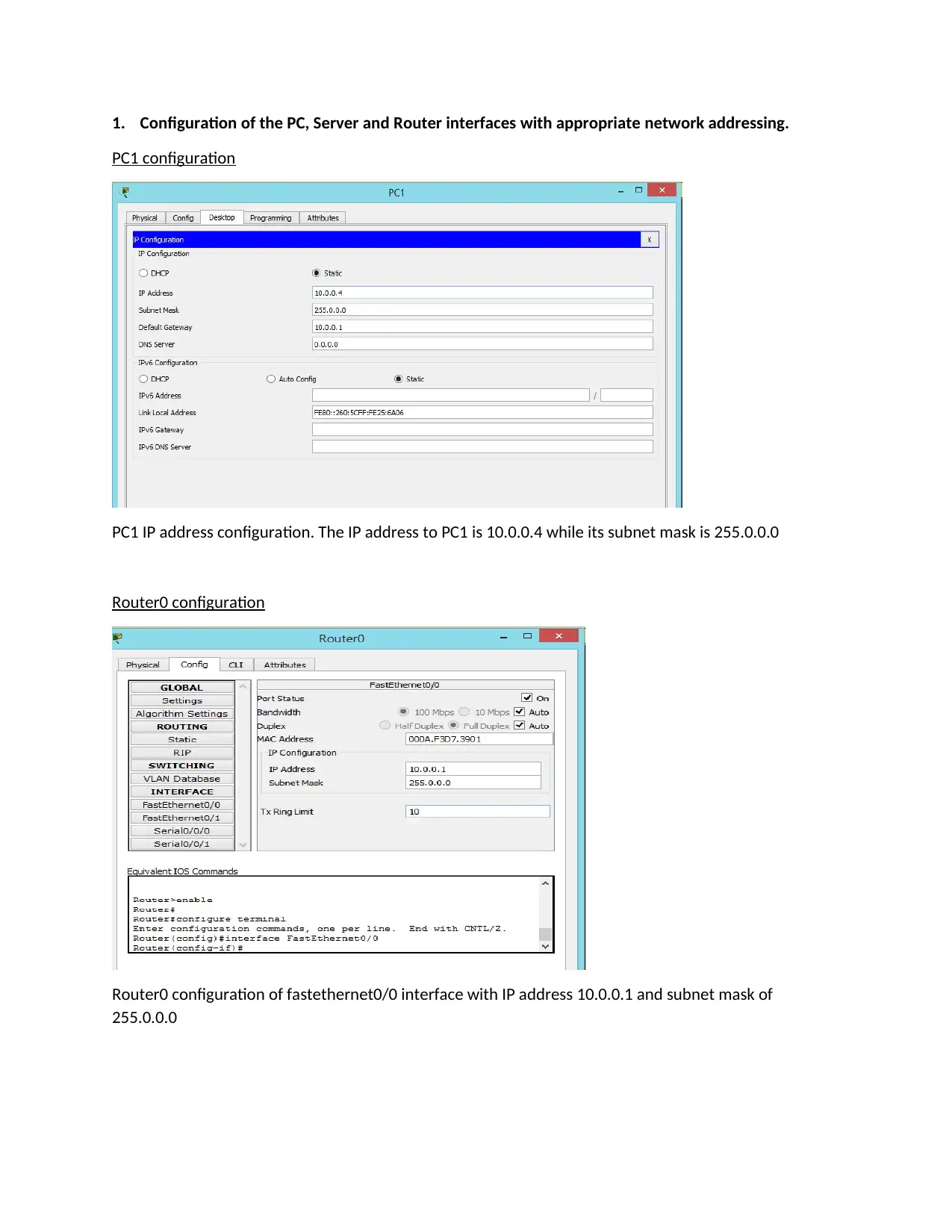
1. Configuration of the PC, Server and Router interfaces with appropriate network addressing.
PC1 configuration
PC1 IP address configuration. The IP address to PC1 is 10.0.0.4 while its subnet mask is 255.0.0.0
Router0 configuration
Router0 configuration of fastethernet0/0 interface with IP address 10.0.0.1 and subnet mask of
255.0.0.0
PC1 configuration
PC1 IP address configuration. The IP address to PC1 is 10.0.0.4 while its subnet mask is 255.0.0.0
Router0 configuration
Router0 configuration of fastethernet0/0 interface with IP address 10.0.0.1 and subnet mask of
255.0.0.0
⊘ This is a preview!⊘
Do you want full access?
Subscribe today to unlock all pages.

Trusted by 1+ million students worldwide
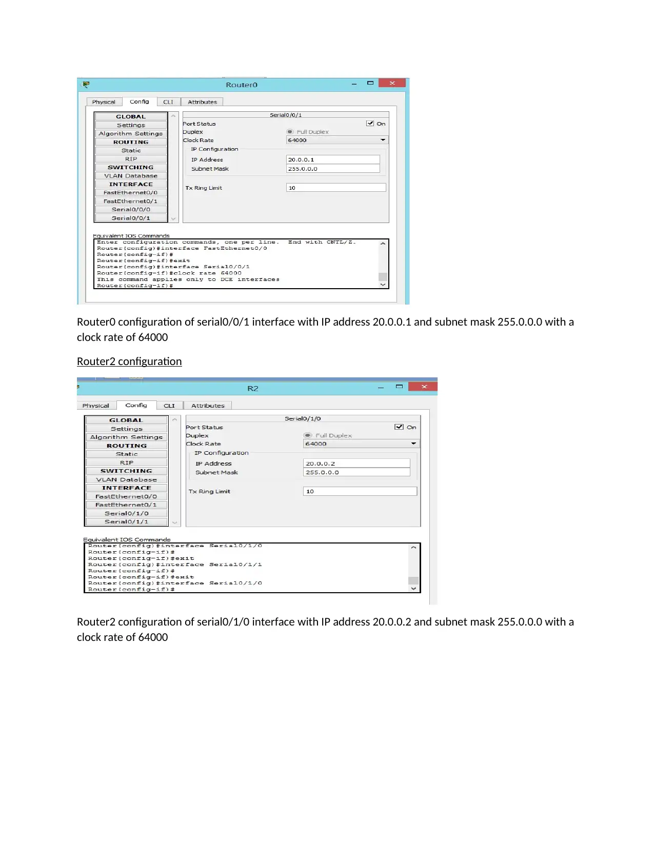
Router0 configuration of serial0/0/1 interface with IP address 20.0.0.1 and subnet mask 255.0.0.0 with a
clock rate of 64000
Router2 configuration
Router2 configuration of serial0/1/0 interface with IP address 20.0.0.2 and subnet mask 255.0.0.0 with a
clock rate of 64000
clock rate of 64000
Router2 configuration
Router2 configuration of serial0/1/0 interface with IP address 20.0.0.2 and subnet mask 255.0.0.0 with a
clock rate of 64000
Paraphrase This Document
Need a fresh take? Get an instant paraphrase of this document with our AI Paraphraser
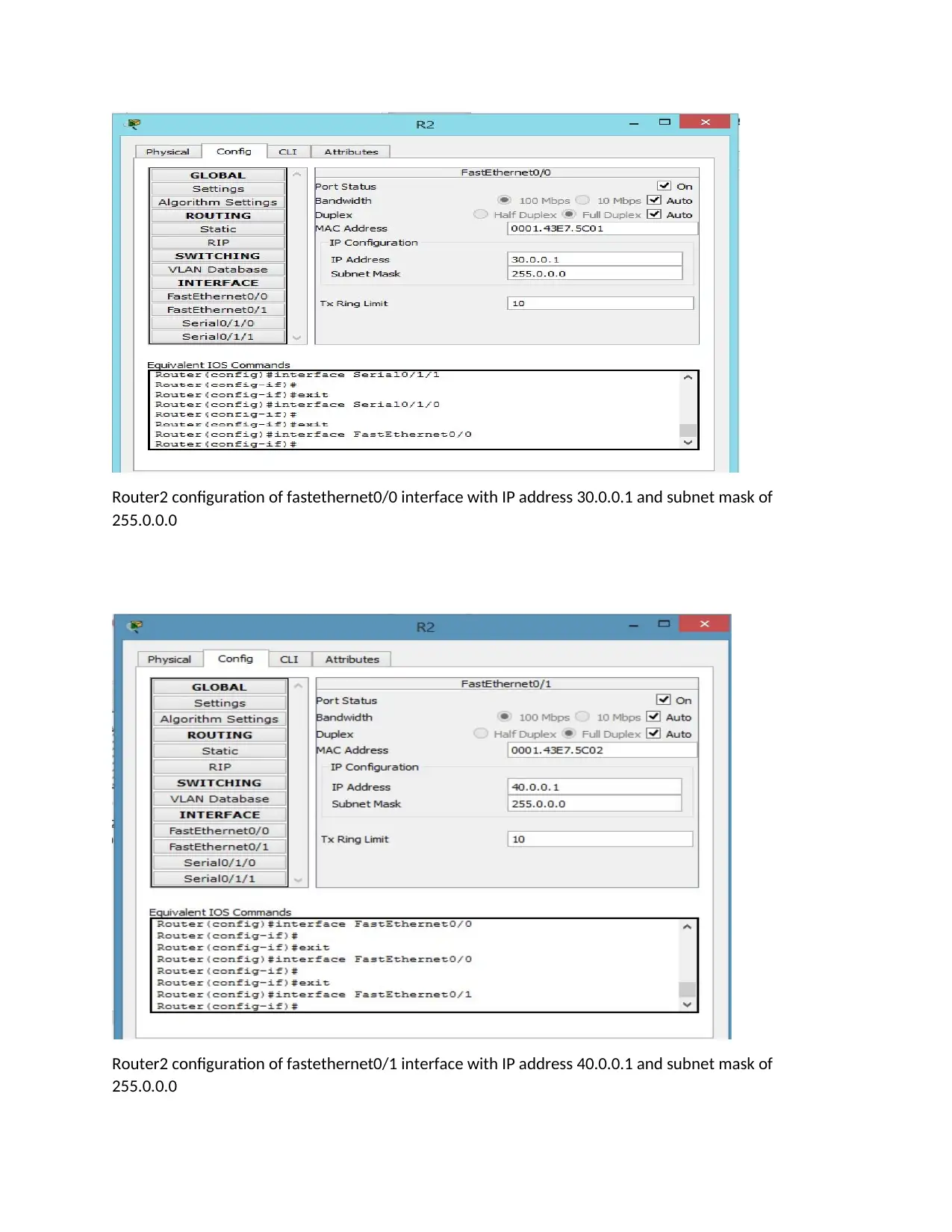
Router2 configuration of fastethernet0/0 interface with IP address 30.0.0.1 and subnet mask of
255.0.0.0
Router2 configuration of fastethernet0/1 interface with IP address 40.0.0.1 and subnet mask of
255.0.0.0
255.0.0.0
Router2 configuration of fastethernet0/1 interface with IP address 40.0.0.1 and subnet mask of
255.0.0.0
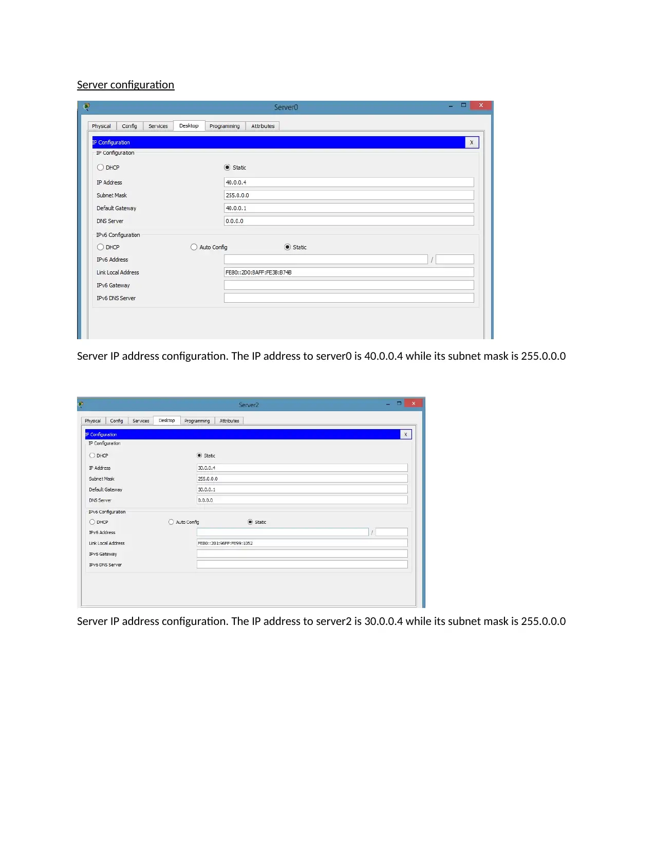
Server configuration
Server IP address configuration. The IP address to server0 is 40.0.0.4 while its subnet mask is 255.0.0.0
Server IP address configuration. The IP address to server2 is 30.0.0.4 while its subnet mask is 255.0.0.0
Server IP address configuration. The IP address to server0 is 40.0.0.4 while its subnet mask is 255.0.0.0
Server IP address configuration. The IP address to server2 is 30.0.0.4 while its subnet mask is 255.0.0.0
⊘ This is a preview!⊘
Do you want full access?
Subscribe today to unlock all pages.

Trusted by 1+ million students worldwide
2. Configuration of routing (IP packet forwarding) on router0 and router2
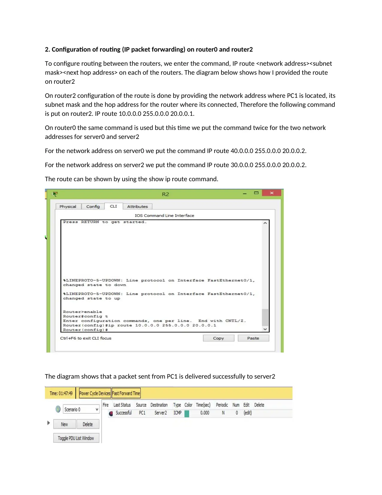
To configure routing between the routers, we enter the command, IP route <network address><subnet
mask><next hop address> on each of the routers. The diagram below shows how I provided the route
on router2
On router2 configuration of the route is done by providing the network address where PC1 is located, its
subnet mask and the hop address for the router where its connected, Therefore the following command
is put on router2. IP route 10.0.0.0 255.0.0.0 20.0.0.1.
On router0 the same command is used but this time we put the command twice for the two network
addresses for server0 and server2
For the network address on server0 we put the command IP route 40.0.0.0 255.0.0.0 20.0.0.2.
For the network address on server2 we put the command IP route 30.0.0.0 255.0.0.0 20.0.0.2.
The route can be shown by using the show ip route command.
The diagram shows that a packet sent from PC1 is delivered successfully to server2
Paraphrase This Document
Need a fresh take? Get an instant paraphrase of this document with our AI Paraphraser
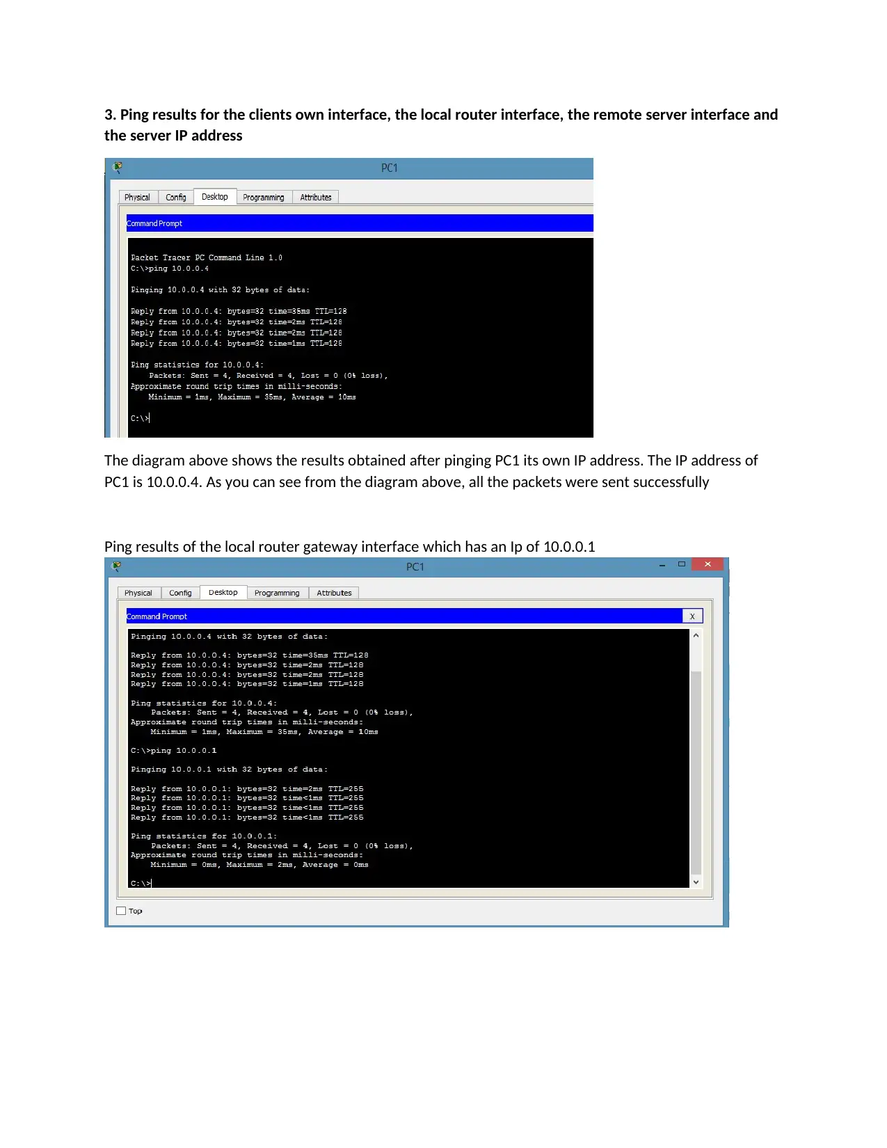
3. Ping results for the clients own interface, the local router interface, the remote server interface and
the server IP address
The diagram above shows the results obtained after pinging PC1 its own IP address. The IP address of
PC1 is 10.0.0.4. As you can see from the diagram above, all the packets were sent successfully
Ping results of the local router gateway interface which has an Ip of 10.0.0.1
the server IP address
The diagram above shows the results obtained after pinging PC1 its own IP address. The IP address of
PC1 is 10.0.0.4. As you can see from the diagram above, all the packets were sent successfully
Ping results of the local router gateway interface which has an Ip of 10.0.0.1
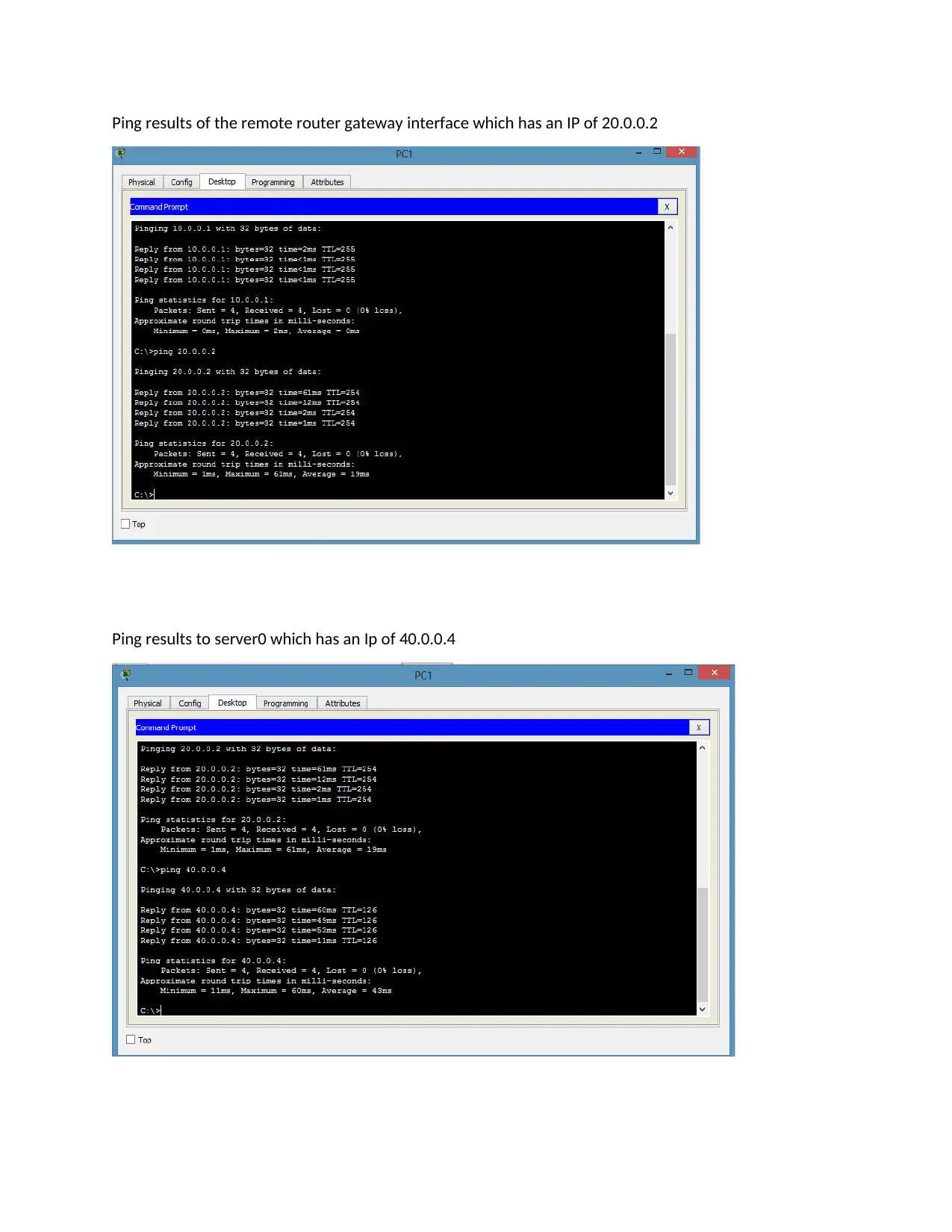
Ping results of the remote router gateway interface which has an IP of 20.0.0.2
Ping results to server0 which has an Ip of 40.0.0.4
Ping results to server0 which has an Ip of 40.0.0.4
⊘ This is a preview!⊘
Do you want full access?
Subscribe today to unlock all pages.

Trusted by 1+ million students worldwide
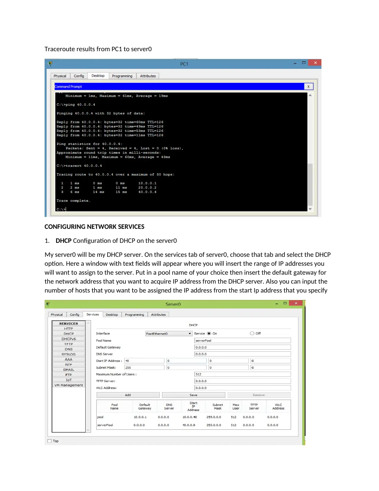
Traceroute results from PC1 to server0
CONFIGURING NETWORK SERVICES
1. DHCP Configuration of DHCP on the server0
My server0 will be my DHCP server. On the services tab of server0, choose that tab and select the DHCP
option. Here a window with text fields will appear where you will insert the range of IP addresses you
will want to assign to the server. Put in a pool name of your choice then insert the default gateway for
the network address that you want to acquire IP address from the DHCP server. Also you can input the
number of hosts that you want to be assigned the IP address from the start Ip address that you specify
Paraphrase This Document
Need a fresh take? Get an instant paraphrase of this document with our AI Paraphraser
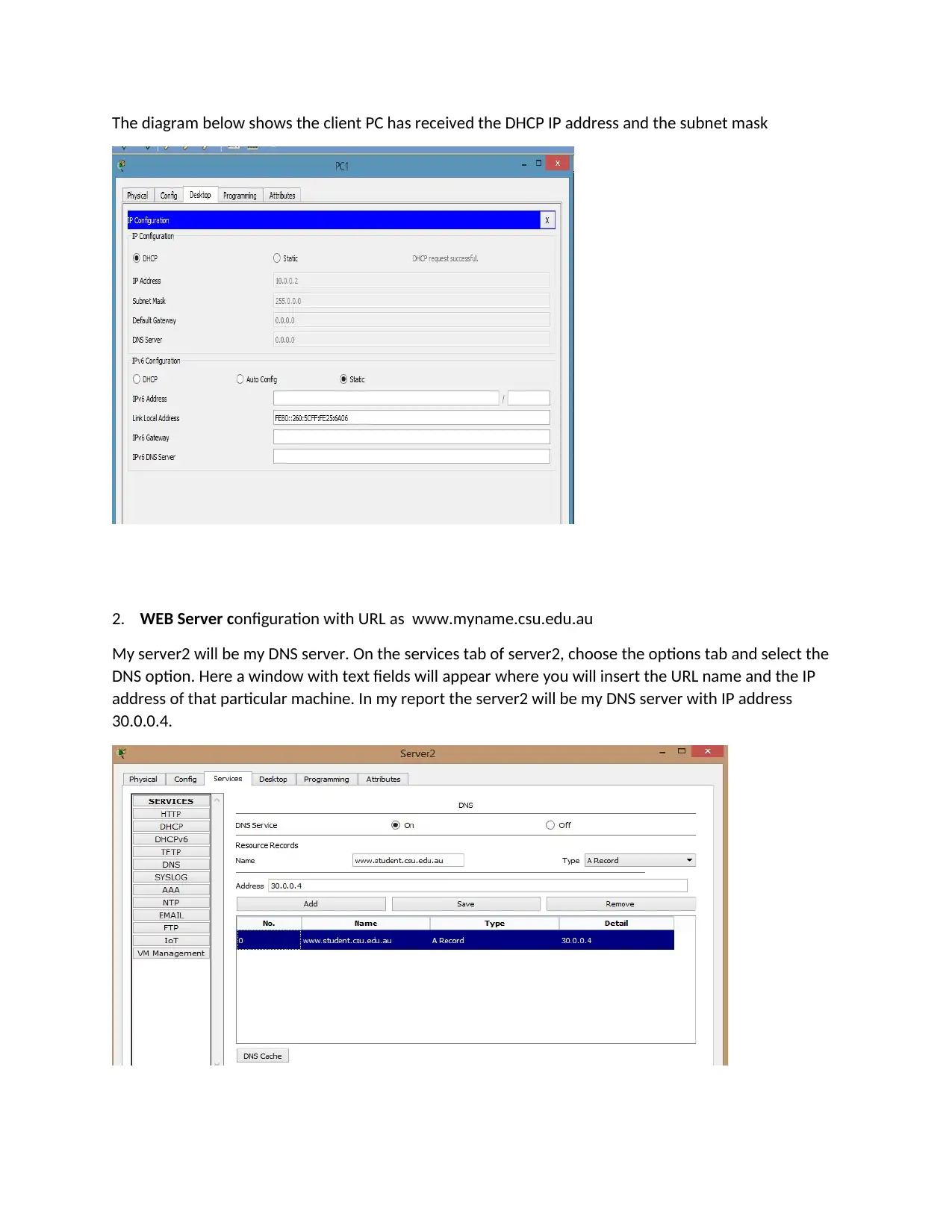
The diagram below shows the client PC has received the DHCP IP address and the subnet mask
2. WEB Server configuration with URL as www.myname.csu.edu.au
My server2 will be my DNS server. On the services tab of server2, choose the options tab and select the
DNS option. Here a window with text fields will appear where you will insert the URL name and the IP
address of that particular machine. In my report the server2 will be my DNS server with IP address
30.0.0.4.
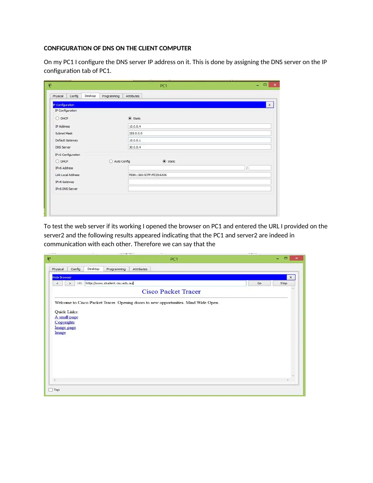
CONFIGURATION OF DNS ON THE CLIENT COMPUTER
On my PC1 I configure the DNS server IP address on it. This is done by assigning the DNS server on the IP
configuration tab of PC1.
To test the web server if its working I opened the browser on PC1 and entered the URL I provided on the
server2 and the following results appeared indicating that the PC1 and server2 are indeed in
communication with each other. Therefore we can say that the
⊘ This is a preview!⊘
Do you want full access?
Subscribe today to unlock all pages.

Trusted by 1+ million students worldwide
1 out of 15
Related Documents
Your All-in-One AI-Powered Toolkit for Academic Success.
+13062052269
info@desklib.com
Available 24*7 on WhatsApp / Email
![[object Object]](/_next/static/media/star-bottom.7253800d.svg)
Unlock your academic potential
Copyright © 2020–2026 A2Z Services. All Rights Reserved. Developed and managed by ZUCOL.


