Question 1 a). The network address 172.27.0.0 /16 is an address of class B in a classful addressing scheme and is categorized to private address type which means the address is reserved for internal use (Fall and Stevens, 2011). Based on the subnet mask of 255.255.0.0, the class B private address type comprises all addresses between 172.16.0.0 to 172.31.255.255 and therefore the address 172.27.0.0 falls in between the range. The above network address has a wildcard address of 0.0.255.255. its IP range starts from 172.27.0.1 to 172.27.255.254 and the broadcast address for this network is 172.27.255.255. The addressing scheme for class B address supports 65534 hosts in the network for the allocation IP address(‘Understanding IP Addressing : Everything You Ever Wanted To Know’, no date)(Montenegro, Kushalnagar, Hui and Culler, 2017). b). In classful addressing scheme, all IP addresses available are split into five classes A, B, C, D and E. Class A, B and C are the common classes of IP addressing while the use of class D is for multicast and class E is rarely used since its reserved (Hsieh, Huang, Huang and Yang, 2010). The classless addressing scheme is also known as Classless Inter-Domain Routing (CIDR) is a mode of assigning and specifying the internet addresses to be employed in inter- domain routing in a flexible means than with the original means of IP address classes. In reference to Figure 1 which employs classless addressing mechanism there are advantages of using it over classful addressing and include: 1.The subnet information in classful addressing is not sent as compared to classless addressing where subnet information is sent. 2.In classless addressing, there is the efficient address- space allocation as compared to classful addressing where addresses are allocated in fixed-size blocks that are of low granularity. 3.In classless addressing the memory, an allocation is in terms of bits and bytes unlike classful where it’s a large chunk of contagious memory. 4.Classless addressing eliminates any available class imbalances where the class doesn’t make up unequal part of ip addressing. 2
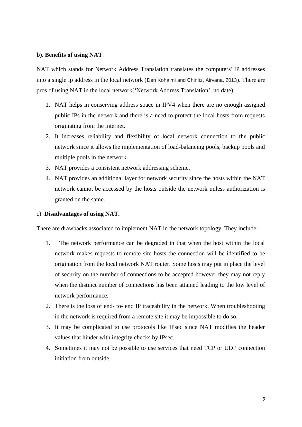
5.There is more efficiency in routing entries in classless addressing. 6.Entities for subnetting in classless addressing are not separate. c). In figure 1 provided three new subnets were added to a local area network using the base network address 172.27.0.0/16. Subnet LAN A supports 60 maximum usable host addresses. Subnet LAN B support 20 maximum usable host addresses and subnet LAN C supports a maximum of 4 usable host addresses. In the additional process, the new subnets did not interfere with the current subnets in the network that were allocated previously rather the base network address was further subdivided to create more room for the new subnet(Chari, Srikrishna and Zhuge,2010). i.The network address and the subnet mask for the subnets are provided as follows in the table. Subnet LANNetwork addressSubnet maskDecimal mask A172.27.0.64/26255.255.255.192 B172.27.0.128/27255.255.255.224 C172.27.0.160/29255.255.255.248 The table shows the network address for the new LAN subnets with their subnet masks. ii.The first, last and broadcast addresses for the subnets are given in the table below. Subnet LANFirst hostLast hostBroadcast address A172.27.0.65172.27.0.126172.27.0.127 B172.27.0.129172.27.0.158172.27.0.159 C172.27.0.161172.27.0.166172.27.0.167 The above table depicts the assignable address range for every subnet listed as the first and last host with their broadcast addresses. 3
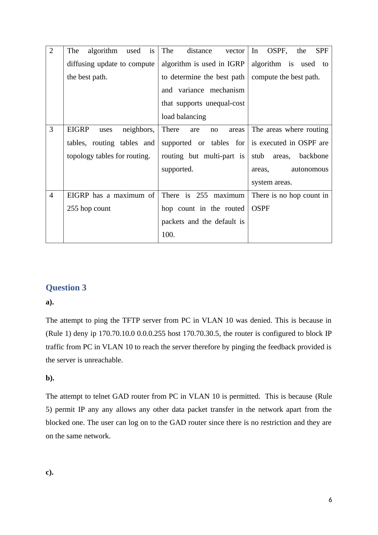
Question 2 a). Difference between distance vector routing and link-state routing. Distance vector routing is a routing algorithm where the router needs to know the direction where to send the packets and not the path to every segment in the network (Hacene, Lehireche, and Meddahi, 2016). This routing algorithm sends its routing table to the immediate neighbors and a router executing the algorithm sends the updates periodically even when the network has no changes. However, the router can confirm the recognized routes and thereby altering the routing table based on information received from a neighboring route that is updated. Link state routing is a routing algorithm in which every router attempts to generate its particular internal map of the topology of the network(Clausen, Dearlove, Jacquet and Herberg, 2014.). At the beginning state, the router is initiated and it sends messages to the network collecting data from the router that is connected to it directly. It also gives information on if the link to reach the router is active or not active and in return, the information is used to construct the topology of the network. The main difference between the link-state routing and distance vector routing is as provided. Distance Vector RoutingLink State Routing 1The router obtains information on the topology from a neighboring route. Therouterobtainsinformationonthe topology of the network. 2The routing algorithm calculates the best routes based on the distance or the few numbers of hopes in the route. Theroutingalgorithmcalculatesthebest route founded on the least cost incurred. 3Theroutingalgorithmupdatesthe routing table fully. The routing algorithm updates only the link state. 4Itsimplementationand management state is simple. Itiscomplextoimplementandnetwork administrator needs to be well trained. 5The convergence time is slow leading to infinity problem The convergence time is high improving its reliability. Table 1: Differences between link routing and vector routing 4
Paraphrase This Document
Need a fresh take? Get an instant paraphrase of this document with our AI Paraphraser
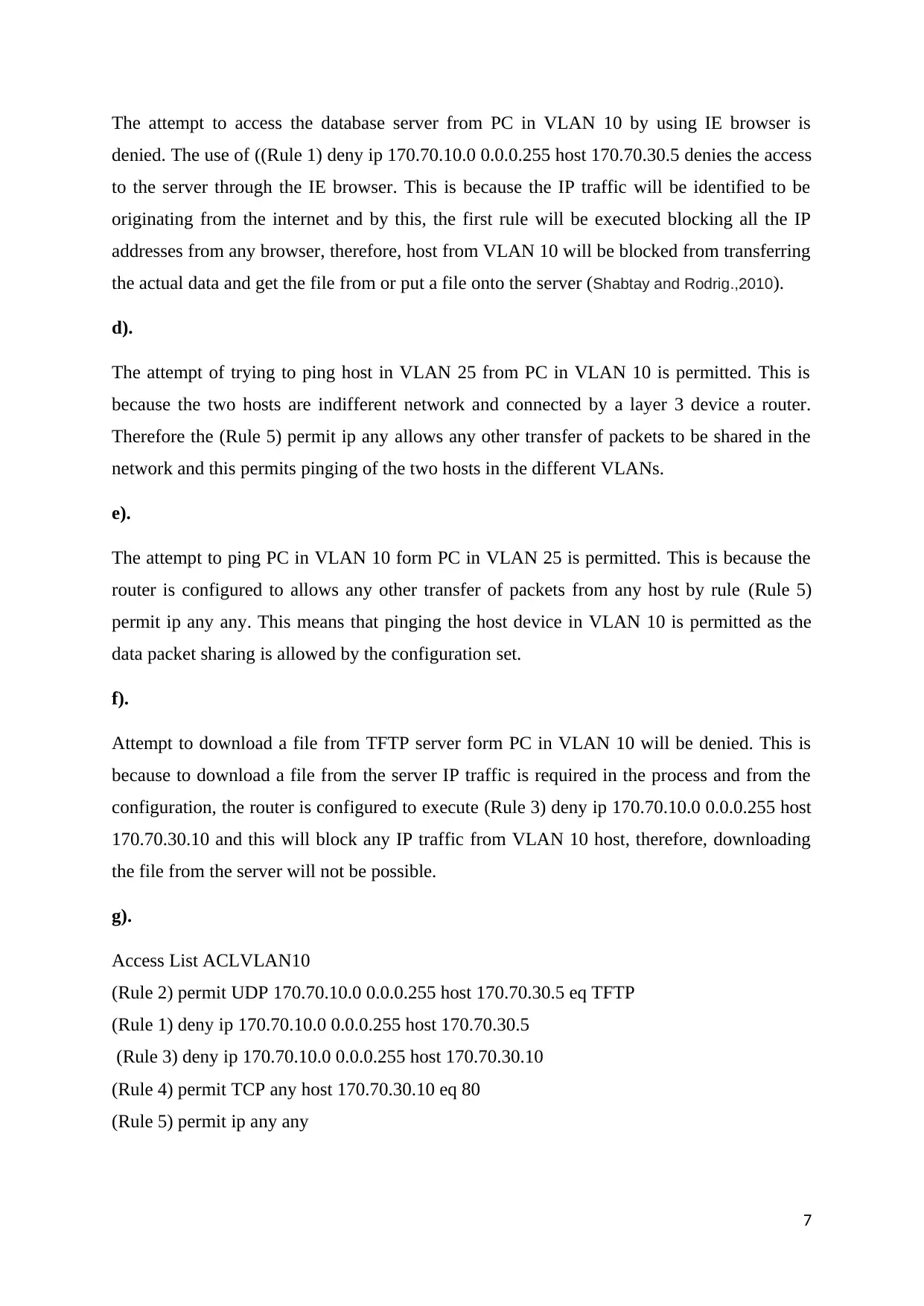
An example of distance vector routing protocols is Interior Gateway Routing Protocol (IGRP) and an example of link-state routing protocols is Open Shortest Path First (OSPF) (Sultanet al., 2010). b). Features of an algorithm that EIGRP uses to determine the best route. Enhance Interior Gateway Protocol (EIGRP) is an interior gateway protocol that scales well and delivers high convergence time with the least network traffic (Vetriselvan, Patiland Mahendran,2014). It relies on Diffused Updated Algorithm (DUAL) to determine the shortest path to a given destination in the network. DUAL has numerous features in its performance and it includes: i.DUAL determines a backup route if it is available. It traces the route to be used for backing up the information in case of failure of the current route. ii.It has room for a Variable-length subnet mask (VLSM). It permits the base network to be divided further into more subnets in the network through the variable subnetting. iii.DUAL recovers a dynamic route in the network. iv.DUAL requests or queries the neighbor for an unknown alternative route. It sends the request to the neighboring router to determine the alternative route. v.It sends out inquiries for alternative routes. The EIGRP keeps all the routes that have been advertised by its neighbors and the metrics are used by DUAL to choose an efficient path. It chooses the route that will be placed in the routing table and if it fails a replacement is chosen by the same DUAL (Mohammed and Elrahim, 2017). The comparison between EIGRP, interior gateway routing protocol (IGRP) which distant vector routing protocol and open shortest path protocol (OSPF) which is link-state routing protocol are as shown. EIGRPIGRPOSPF 1The metricssuch as load, reliability, bandwidth, delay and are used. It uses bandwidth, delay, load reliability, and MTU metrics. Theusedmetricsin OSPF are bandwidth and relay 5
2Thealgorithmusedis diffusing update to compute the best path. Thedistancevector algorithm is used in IGRP to determine the best path andvariancemechanism that supports unequal-cost load balancing InOSPF,theSPF algorithmisusedto compute the best path. 3EIGRPusesneighbors, tables,routingtablesand topology tables for routing. Therearenoareas supportedortablesfor routingbutmulti-partis supported. The areas where routing is executed in OSPF are stubareas,backbone areas,autonomous system areas. 4EIGRP has a maximum of 255 hop count Thereis255maximum hopcountintherouted packets and the default is 100. There is no hop count in OSPF Question 3 a). The attempt to ping the TFTP server from PC in VLAN 10 was denied. This is because in (Rule 1) deny ip 170.70.10.0 0.0.0.255 host 170.70.30.5, the router is configured to block IP traffic from PC in VLAN 10 to reach the server therefore by pinging the feedback provided is the server is unreachable. b). The attempt to telnet GAD router from PC in VLAN 10 is permitted.This is because(Rule 5) permitIPany anyallows any other data packet transfer in the network apart from the blocked one. The user can log on to the GAD router since there is no restriction and they are on the same network. c). 6
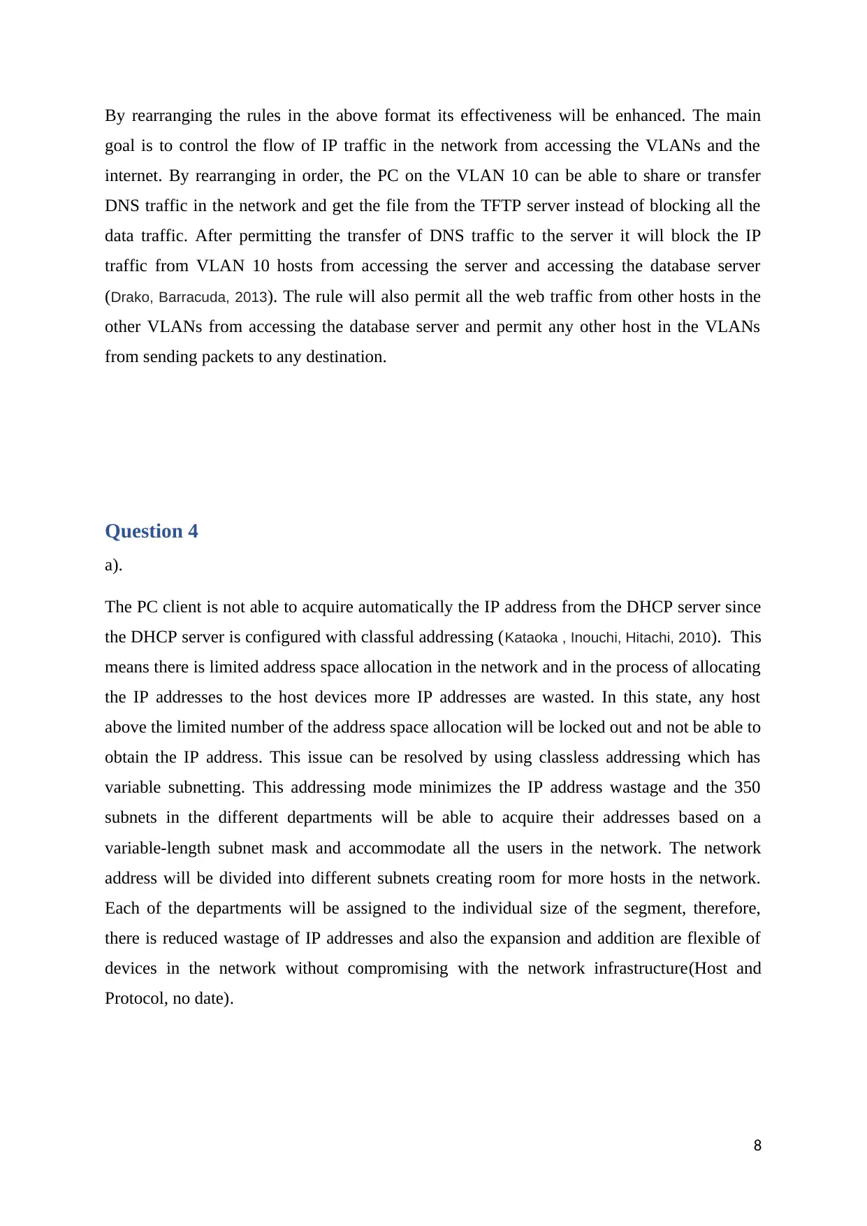
The attempt to access the database server from PC in VLAN 10 by using IE browser is denied. The use of((Rule 1) deny ip 170.70.10.0 0.0.0.255 host 170.70.30.5denies the access to the server through the IE browser. This is because the IP traffic will be identified to be originating from the internet and by this, the first rule will be executed blocking all the IP addresses from any browser, therefore, host from VLAN 10 will be blocked from transferring the actual data and get the file from or put a file onto the server (Shabtay and Rodrig.,2010). d). The attempt of trying to ping host in VLAN 25 from PC in VLAN 10 is permitted. This is because the two hosts are indifferent network and connected by a layer 3 device a router. Therefore the(Rule 5) permit ip anyallows any other transfer of packets to be shared in the network and this permits pinging of the two hosts in the different VLANs. e). The attempt to ping PC in VLAN 10 form PC in VLAN 25 is permitted. This is because the router is configured to allows any other transfer of packets from any host by rule(Rule 5) permit ip any any. This means that pinging the host device in VLAN 10 is permitted as the data packet sharing is allowed by the configuration set. f). Attempt to download a file from TFTP server form PC in VLAN 10 will be denied. This is because to download a file from the server IP traffic is required in the process and from the configuration, the router is configured to execute(Rule 3) deny ip 170.70.10.0 0.0.0.255 host 170.70.30.10and this will block any IP traffic from VLAN 10 host, therefore, downloading the file from the server will not be possible. g). Access List ACLVLAN10 (Rule 2) permit UDP 170.70.10.0 0.0.0.255 host 170.70.30.5 eq TFTP (Rule 1) deny ip 170.70.10.0 0.0.0.255 host 170.70.30.5 (Rule 3) deny ip 170.70.10.0 0.0.0.255 host 170.70.30.10 (Rule 4) permit TCP any host 170.70.30.10 eq 80 (Rule 5) permit ip any any 7
Secure Best Marks with AI Grader
Need help grading? Try our AI Grader for instant feedback on your assignments.
By rearranging the rules in the above format its effectiveness will be enhanced. The main goal is to control the flow of IP traffic in the network from accessing the VLANs and the internet. By rearranging in order, the PC on the VLAN 10 can be able to share or transfer DNS traffic in the network and get the file from the TFTP server instead of blocking all the data traffic. After permitting the transfer of DNS traffic to the server it will block the IP traffic from VLAN 10 hosts from accessing the server and accessing the database server (Drako, Barracuda, 2013). The rule will also permit all the web traffic from other hosts in the other VLANs from accessing the database server and permit any other host in the VLANs from sending packets to any destination. Question 4 a). The PC client is not able to acquire automatically the IP address from the DHCP server since the DHCP server is configured with classful addressing (Kataoka,Inouchi, Hitachi, 2010). This means there is limited address space allocation in the network and in the process of allocating the IP addresses to the host devices more IP addresses are wasted. In this state, any host above the limited number of the address space allocation will be locked out and not be able to obtain the IP address. This issue can be resolved by using classless addressing which has variable subnetting. This addressing mode minimizes the IP address wastage and the 350 subnets in the different departments will be able to acquire their addresses based on a variable-length subnet mask and accommodate all the users in the network. The network address will be divided into different subnets creating room for more hosts in the network. Each of the departments will be assigned to the individual size of the segment, therefore, there is reduced wastage of IP addresses and also the expansion and addition are flexible of devices in the network without compromising with the network infrastructure(Host and Protocol, no date). 8
b). Benefits of using NAT. NAT which stands for Network Address Translation translates the computers' IP addresses into a single Ip address in the local network (Den Kohalmi and Chinitz, Airvana, 2013). There are pros of using NAT in the local network(‘Network Address Translation’, no date). 1.NAT helps in conserving address space in IPV4 when there are no enough assigned public IPs in the network and there is a need to protect the local hosts from requests originating from the internet. 2.It increases reliability and flexibility of local network connection to the public network since it allows the implementation of load-balancing pools, backup pools and multiple pools in the network. 3.NAT provides a consistent network addressing scheme. 4.NAT provides an additional layer for network security since the hosts within the NAT network cannot be accessed by the hosts outside the network unless authorization is granted on the same. c).Disadvantages of using NAT. There are drawbacks associated to implement NAT in the network topology. They include: 1.The network performance can be degraded in that when the host within the local network makes requests to remote site hosts the connection will be identified to be origination from the local network NAT router. Some hosts may put in place the level of security on the number of connections to be accepted however they may not reply when the distinct number of connections has been attained leading to the low level of network performance. 2.There is the loss of end- to- end IP traceability in the network. When troubleshooting in the network is required from a remote site it may be impossible to do so. 3.It may be complicated to use protocols like IPsec since NAT modifies the header values that hinder with integrity checks by IPsec. 4.Sometimes it may not be possible to use services that need TCP or UDP connection initiation from outside. 9
d). DHCP use and it's working in network communication. Dynamic Host Configuration Protocol is an application layer protocol that is used to allocate network configuration parameters like network IP addresses, the Subnet masks, network default gateway to the end or host devices in the IP network. It employs the client-server architecture where the client requests for IP address from the DHCP server and the DHCP server having an IP address pool assigns each host with internet protocol address. The DHCP works in the following steps to facilitates communication between the client and the server(‘Chapter 9.pdf’, no date). i.The host devices connecting the network either by the cable or the wireless connection sends the DHCP to discover message to hosts in the layer 2 section and the frame with the DISCOVER message reaches the DHCP server. ii.When the DHCP server receives the discover message, through unicast it proposes the IP addressing to provide to client host and the OFFER message has the suggested IP address for the clients, subnet mask, default gateway IP and DNS server IP (Kanekarand Foschiano, 2011). iii.When the clients receive the proposal it thereby requests official information sending REQUEST message to the server through unicast. iv.The server then sends an ACKNOWLEDGE message to confirm the lease of DHCP to the client and now the client is permitted to use the new IP address. In the current cyber world, there is increased cyber attackers and hackers whose main target is to compromise data in the network and the entire network security policies. The DHCP communication can be compromised through denial of service attacks on the DHCP server. This is done by overflowing the server with lease requests and in turn draining or depleting the number of leases available in the server for other DHCP clients. Another attack is DHCP starvation where the address space available to DHCP servers for a specified period is exhausted by the attacker. Another attack is DHCP sniffing where the DHCP server is set on the network by a hacker named Rogue DHCP server. An attacker then sources the clients with fake Ip addresses and other network information to snoop into the data packets. e).DHCP excluded-address 10
Paraphrase This Document
Need a fresh take? Get an instant paraphrase of this document with our AI Paraphraser
This is a global configuration command that prevents the specific IP addresses from being assigned by the routers DHCP server. It prevents conflicting IP addresses on the servers and routers in the network that have statically assigned IP addresses. The example of the syntax for the command is:Router(config)# ip DHCP excluded-address 172.16.1.103 172.16.1.199 References Fall, K.R. and Stevens, W.R., 2011.TCP/IP illustrated, volume 1: The protocols. addison-Wesley. Montenegro, G., Kushalnagar, N., Hui, J. and Culler, D., 2017. Transmission of IPv6 packets over IEEE 802.15. 4 networks.Internet proposed standard RFC,4944, p.130. Hsieh, S.Y., Huang, C.W., Huang, Y.L. and Yang, Y.C., 2010, May. A novel dynamic router-tables designforIPlookupandupdate.In20105thInternationalConferenceonFutureInformation Technology(pp. 1-6). IEEE. Chari, A., Srikrishna, D. and Zhuge, J., Tropos Networks Inc, 2010.Method of subnet roaming within a network. U.S. Patent 7,649,866. Hacene, S.B., Lehireche, A. and Meddahi, A., 2016. Predictive preemptive ad hoc on-demand distance vector routing.Malaysian Journal of Computer Science,19(2), pp.189-195. Clausen, T., Dearlove, C., Jacquet, P. and Herberg, U., 2014. The optimized link state routing protocol version 2.draft-ietf-manet-olsrv2-04. txt, July,7. Sultan, N.T., Jamieson, D.D. and Simpson, V.A., Avaya Holdings Ltd, 2010.Policy-based forwarding in open shortest path first (OSPF) networks. U.S. Patent 7,831,733. Vetriselvan, V., Patil, P.R. and Mahendran, M., 2014. Survey on the RIP, OSPF, EIGRP routing protocols.International Journal of Computer Science and Information Technologies,5(2), pp.1058- 1065. Mohammed, Z.K.A. and Elrahim, A.G.A., 2017. Performance Evaluation Comparison of RIP, IGRP, EIGRP, and OSPF routing protocols in UMTS. Shabtay,L.andRodrig,B.,AvayaCommunicationsIsraelLtd,2011.IPmulticastinVLAN environment. U.S. Patent 7,924,837. Wang, Z., Jian, R., Sun, Y. and Song, C., Intel Corp, 2011.Server side TFTP flow control. U.S. Patent 7,934,007. Drako, D., Barracuda Networks Inc, 2013.Policy-managed DNS server for to control network traffic. U.S. Patent 8,447,856. 11
Kataoka, M. and Inouchi, H., Hitachi Ltd, 2010.Network system, dhcp server device, and dhcp client device. U.S. Patent Application 12/615,452. Den, M., Kohalmi, S. and Chinitz, L.M., Airvana Inc, 2013.Network address translation for tunnel mobility. U.S. Patent 8,345,694. Kanekar, B.M. and Foschiano, M.E., Cisco Technology Inc, 2011.Extending sso for DHCP snooping to two box redundancy. U.S. Patent 7,903,647. 12