Wastewater Treatment Plant Design: Oldcastle Activated Sludge System
VerifiedAdded on 2019/09/30
|19
|2015
|269
Report
AI Summary
This report presents the design of an activated sludge plant for the Oldcastle municipal co-operation, with a design capacity of 1500 population equivalents. The aim is to design the plant based on wastewater flow and preliminary laboratory bacterial growth analysis. The methodology includes determining kinetic parameters like the cell yield coefficient and specific growth rate using the Monod equation, analyzing BOD levels, and comparing experimental and model growth rates. The results section presents graphs of various BOD levels over time, discussing the challenges in obtaining smooth curves and the variability in data. The report also explores the nitrification capabilities of the sludge, detailing the biochemical reactions and bacterial species involved. Data analysis conflicts arise due to variability in VSS measurements. Comparisons of total cell numbers from flow cytometer and qPCR techniques are provided. The conclusion highlights the challenges in aligning experimental and model results, while still confirming the sludge's suitability for nitrification. Design calculations are included, with references to relevant research papers.

[Document title]
[Document subtitle]
[DATE]
Microsoft
[Company address]
[Document subtitle]
[DATE]
Microsoft
[Company address]
Paraphrase This Document
Need a fresh take? Get an instant paraphrase of this document with our AI Paraphraser
Table of Contents
Introduction:..........................................................................................................................................2
Aim:...................................................................................................................................................2
Objective:..........................................................................................................................................2
Methodology:........................................................................................................................................2
Results and discussion:..........................................................................................................................5
Sludge is capable of nitrification:...........................................................................................................8
Data Analysis conflict:............................................................................................................................9
Comparison of total cell numbers from flow cytometer and qPCR technique:...................................10
Conclusion:..........................................................................................................................................11
References...........................................................................................................................................12
1 | P a g e

Introduction:
The waste water treatment plant at Oldcastle will built to serve the agglomeration of
Oldcastle municipal co-operation Meath with the design capacity of 1500 population. The
construction of a new wastewater treatment plant to serve the population of the Oldcastle
commenced in upcoming year. The construction of this new plant will be completed in
upcoming next year. The following calculation have been prepare as per requirement of
wastewater plant. The process and to obtain design parameters are discuss in report segment.
Aim:
To design an activated sludge plant for Oldcastle residencies from the total amount of
population done wastewater flow.
Objective:
Design municipal activated sludge wastewater treatment plant for Oldcastle city through the
preliminary laboratory bacterial growth and utilising wastewater at that area.
To determine the substrate utilisation and growth rates for sludge from the exponential
growth phase of growth.
Plot data to estimate maximum specific growth rate and Ks values from flow cytometry total
counts of bacteria, also obtain maximum BOD utilisation rates and Ks value for wastewater
samples.
Methodology:
Kinematic parameter to design active sludge plant and methodology of obtain kinetic
parameters .The important kinetic parameters requires for process design include as
following:
Y: The cell of yield co-efficient define as the mass of activated sludge per unit of substrate
removal (mg VSS/mg COD)
Kd =The endogenous decay rate ( 1
day )
μmax =the maximum Specific growthrate ( 1
day )
Ks =Shape factor of Monod equation
In order to find specific growth rate following formula used.
2 | P a g e
⊘ This is a preview!⊘
Do you want full access?
Subscribe today to unlock all pages.

Trusted by 1+ million students worldwide

Monod equation:
μ=μmax
S
K s +S
Where, S = Subtraction concentration (mg/L)
The following graph plot from the given data of BOD and time duration in order to find the
experimental growth rate and model growth rate. To fine the value of experimental growth
rate of individual BOD, that obtain by the equation of line of individual graph rate. The slope
value indicate value of growth rate.( Molinos-Senante, M,et. al. 2017)
The above graph have individual growth rate at respective Biochemical Oxygen Demand
which are μ3000=0.0101 , μ2000=0.0211 , μ1500=0.0143 , μ600=0.0022 , μ400=0.014 ,
μ100=0.008 per day .
In order to find the model growth rate, it is require to use experimental growth rate to obtain
model growth rate by following formula:
(Model growthrate)3000= μmax x BOD
K S +BOD
¿ 0.43754095 x 1500
52.43312146+ 1500
¿ 0.422763091
❑ day
( Model growth rate )2000= 0.43754095 x 1000
52.43312146+ 1000
¿ 0.415742284 /day
( Model growth rate )1500= 0.43754095 x 750
52.43312146+750
¿ 0.408950857/day
( Model growth rate )600= 0.43754095 x 300
52.43312146+300
¿ 0.372445939 ❑
day
3 | P a g e
Paraphrase This Document
Need a fresh take? Get an instant paraphrase of this document with our AI Paraphraser
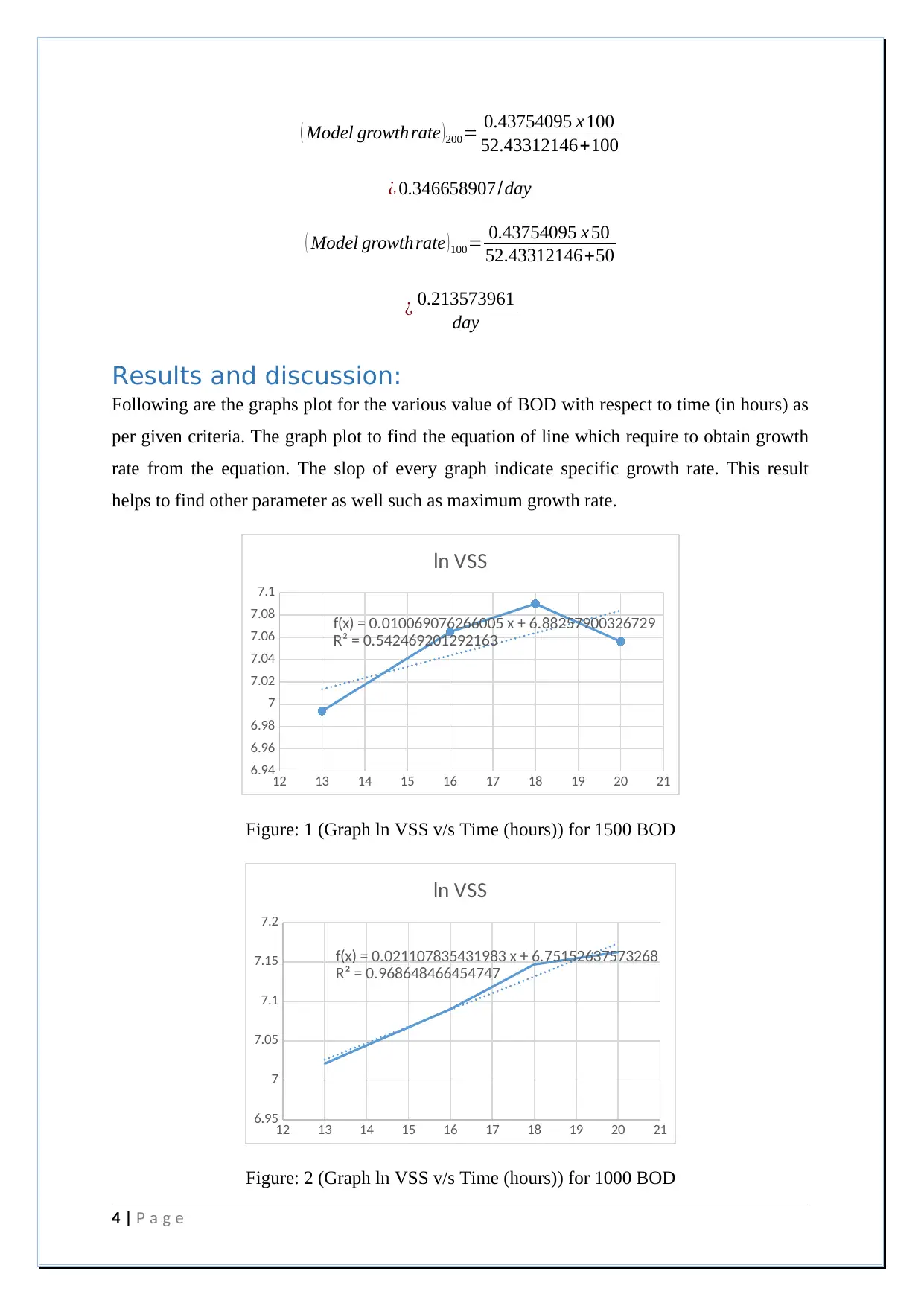
( Model growth rate )200= 0.43754095 x 100
52.43312146+100
¿ 0.346658907/day
( Model growth rate )100= 0.43754095 x 50
52.43312146+50
¿ 0.213573961
day
Results and discussion:
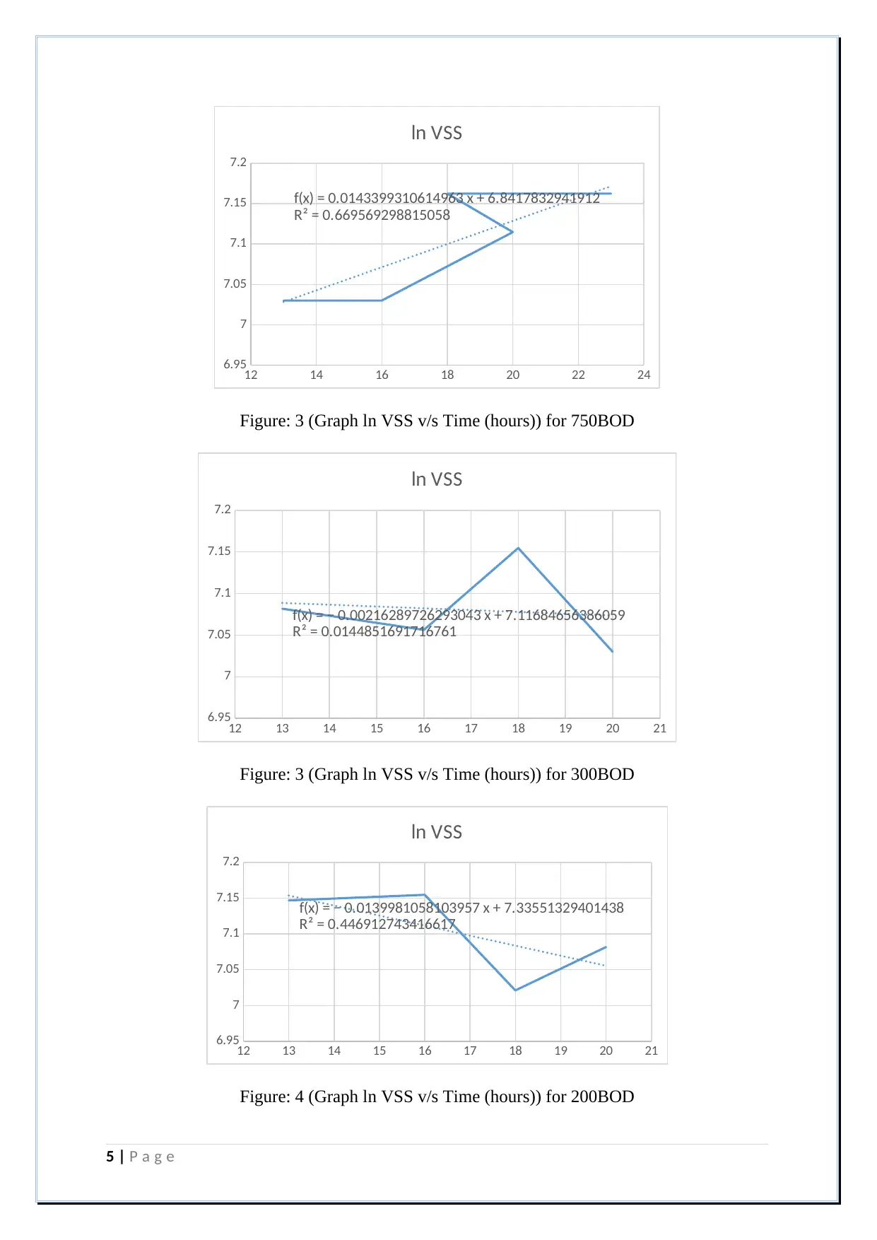
Following are the graphs plot for the various value of BOD with respect to time (in hours) as
per given criteria. The graph plot to find the equation of line which require to obtain growth
rate from the equation. The slop of every graph indicate specific growth rate. This result
helps to find other parameter as well such as maximum growth rate.
12 13 14 15 16 17 18 19 20 21
6.94
6.96
6.98
7
7.02
7.04
7.06
7.08
7.1
f(x) = 0.010069076266005 x + 6.88257900326729
R² = 0.542469201292163
ln VSS
Figure: 1 (Graph ln VSS v/s Time (hours)) for 1500 BOD
12 13 14 15 16 17 18 19 20 21
6.95
7
7.05
7.1
7.15
7.2
f(x) = 0.021107835431983 x + 6.75152637573268
R² = 0.968648466454747
ln VSS
Figure: 2 (Graph ln VSS v/s Time (hours)) for 1000 BOD
4 | P a g e
12 14 16 18 20 22 24
6.95
7
7.05
7.1
7.15
7.2
f(x) = 0.0143399310614963 x + 6.8417832941912
R² = 0.669569298815058
ln VSS
Figure: 3 (Graph ln VSS v/s Time (hours)) for 750BOD
12 13 14 15 16 17 18 19 20 21
6.95
7
7.05
7.1
7.15
7.2
f(x) = − 0.00216289726293043 x + 7.11684656386059
R² = 0.0144851691716761
ln VSS
Figure: 3 (Graph ln VSS v/s Time (hours)) for 300BOD
12 13 14 15 16 17 18 19 20 21
6.95
7
7.05
7.1
7.15
7.2
f(x) = − 0.0139981058103957 x + 7.33551329401438
R² = 0.446912743416617
ln VSS
Figure: 4 (Graph ln VSS v/s Time (hours)) for 200BOD
5 | P a g e
6.95
7
7.05
7.1
7.15
7.2
f(x) = 0.0143399310614963 x + 6.8417832941912
R² = 0.669569298815058
ln VSS
Figure: 3 (Graph ln VSS v/s Time (hours)) for 750BOD
12 13 14 15 16 17 18 19 20 21
6.95
7
7.05
7.1
7.15
7.2
f(x) = − 0.00216289726293043 x + 7.11684656386059
R² = 0.0144851691716761
ln VSS
Figure: 3 (Graph ln VSS v/s Time (hours)) for 300BOD
12 13 14 15 16 17 18 19 20 21
6.95
7
7.05
7.1
7.15
7.2
f(x) = − 0.0139981058103957 x + 7.33551329401438
R² = 0.446912743416617
ln VSS
Figure: 4 (Graph ln VSS v/s Time (hours)) for 200BOD
5 | P a g e
⊘ This is a preview!⊘
Do you want full access?
Subscribe today to unlock all pages.

Trusted by 1+ million students worldwide

12 13 14 15 16 17 18 19 20 21
6.9
6.95
7
7.05
7.1
7.15
f(x) = 0.00803947086254318 x + 6.91619745382436
R² = 0.217351534319166
ln VSS
Figure: 5 (Graph ln VSS v/s Time (hours)) for 50BOD
0 200 400 600 800 1000 1200 1400 1600
0
0.05
0.1
0.15
0.2
0.25
0.3
0.35
0.4
0.45
Experimental μ (/d) Model μ (/d)
Figure: 6 Results for experimental growth rate and model growth rate.
The above all graphs have significant results in order to find the behaviour of specific growth
rate with respect to time. It could be easily found that the graphs have no specific straight to
find the perfect curve but the data varies with time and so that it is difficult to finds the
equation of line without % error. (Sin, G.et.al. 2017) If value of R in graph nears to 0.85
to 0.95 then it could be perfect. But there are many result have no specific straight line and
results may deviate from the line. While choosing the value for specific growth rate, then
require to choose slope value from the individual graph. The value of slope indicate the
specific growth rate of the individual BOD with reference to time. The further calculation in
order to obtain value of model value find from following equation and calculation given.
Also describe different parameter and calculation. The design parameter like to design
6 | P a g e
Paraphrase This Document
Need a fresh take? Get an instant paraphrase of this document with our AI Paraphraser

SRT/SF, effluent concentration achieved, obtained value of HRT and volume of activated
sludge aeriation tank.
μ max ¿ 0.43754095/day
Ks=52.43312146
Qmax= μ max
Y =0.43754095
0.54 =0.810261019
Sludge is capable of nitrification:
Nitrification: it is the sequential conversion of ammonia to nitrite and ultimately nitrate.
Nitrifies are dependent on organotrophs to reduce BOD to relatively low concentration. In
case, if BOD can cause a significant oxygen demand that may intense to drop in D.O. which
adversely affect the nitrifying bacteria. Fluctuations in BOD loading may raise to intermittent
nitrification.( Harms, G.et. al. 2017)
The wastewater nitrification have work as following procedure:
As defined earlier that: Ammonia Nitrite Nitrate.
NH 4+++1.5 02 → N O2−¿+H 2 O +2 H + ¿¿
N O2−¿+ 0.5O2−→ N O3−¿¿ ¿
The overall reaction is as following:
NH 4++2 O 2−→ N O3−¿+2 H +H 2 O ¿
Ammonia is the wastewater could originate from a variety of source, for an active sludge
system, the nitrification have under aerobic conditions.
The nitrification is a bio-chemical reaction that happen inside the bacteria.
There are two species of bacteria are consider for the process which are Nitrosomonas
and Nitrobacter.
These becteria are considerable known as nitrifiers and that are autotrophic that mean
they are collecting their carbon source from inorganic carbon or carbon dioxide.
In nitrifying activated sludge process there are only
As per given condition and results are indicate that 3 to 10% of the bacteria is nitrifies.
7 | P a g e

( Benedetti, L, 2017 ) (For the healthy and comparatively stable population of nitrifiers
will not exist without certain condition.
A healthy and stable population of nitrifiers (Nitrosomonas and Nitrobacter) will not exist
without the following conditions:
1. Presence of oxygen: which is seen in chemical equation and formulation.
2. BOD: which is already present in chemical equation indicate that capable for
nitrification.
3. Alkalinity: it is require to maintain alkalinity in order to maintain nitrification, in
case if alkaline not present then it require to add from additional source to maintain
nitrification.
Considering all aspect of processes, requirement and results indicate that the wastewater
sludge is capable for nitrification.
Data Analysis conflict:
Some experiment runs may suffer from variability in VSS analyses used to measure growth
rate. If the sample was not carefully taken, then variability in the VSS measurements at each
time may be even greater than the net growth of microorganism that leads to kinetic study
inaccurate. The reactor contents must be mixed energetically to disperse the mixture
uniformly before taking samples. Triplicate VSS and duplicate COD sample should be
analysed. It may be desirable to increase the F/M above typical values. (Harms, G, et. al.
2017) This way major amount of growth can be attained. The experimental data collect
runs with the wastewater. As shown in above figure that experimental growth rate have not
smooth curve which is required. But the curve goes up and down as per opposite from the
idea condition. So the data analysis conflict arise because of selection of data and plotted
over the results for the smooth and idealised curve. As model growth rate have significant
smooth curve which is vast difference between experimental and model growth rate which is
not ideal situation.
8 | P a g e
⊘ This is a preview!⊘
Do you want full access?
Subscribe today to unlock all pages.

Trusted by 1+ million students worldwide

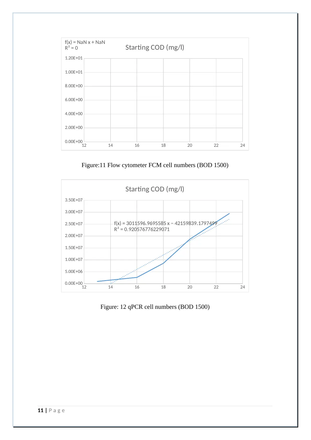
Comparison of total cell numbers from flow cytometer
and qPCR technique:
12 14 16 18 20 22 24
0.00E+00
2.00E+00
4.00E+00
6.00E+00
8.00E+00
1.00E+01
1.20E+01
f(x) = NaN x + NaN
R² = 0 Starting COD (mg/l)
Figure:7 Flow cytometer FCM cell numbers (BOD 3000)
12 14 16 18 20 22 24
0.00E+00
2.00E+09
4.00E+09
6.00E+09
8.00E+09
1.00E+10
1.20E+10
f(x) = 1111697150.4003 x − 16116561274.9933
R² = 0.902964608656834
Starting COD (mg/l)
Figure: 8 qPCR cell numbers (BOD 3000)
9 | P a g e
Paraphrase This Document
Need a fresh take? Get an instant paraphrase of this document with our AI Paraphraser
12 14 16 18 20 22 24
0.00E+00
2.00E+00
4.00E+00
6.00E+00
8.00E+00
1.00E+01
1.20E+01
f(x) = NaN x + NaN
R² = 0 Starting COD (mg/l)
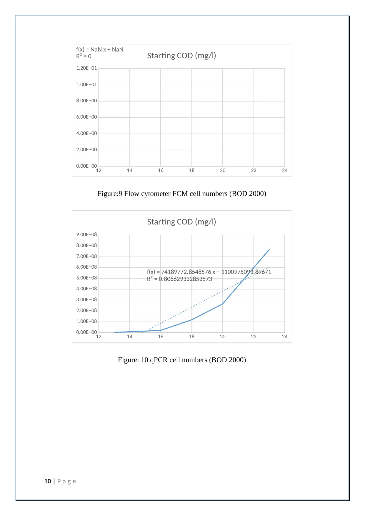
Figure:9 Flow cytometer FCM cell numbers (BOD 2000)
12 14 16 18 20 22 24
0.00E+00
1.00E+08
2.00E+08
3.00E+08
4.00E+08
5.00E+08
6.00E+08
7.00E+08
8.00E+08
9.00E+08
f(x) = 74189772.8548576 x − 1100975093.89671
R² = 0.806629332853573
Starting COD (mg/l)
Figure: 10 qPCR cell numbers (BOD 2000)
10 | P a g e
0.00E+00
2.00E+00
4.00E+00
6.00E+00
8.00E+00
1.00E+01
1.20E+01
f(x) = NaN x + NaN
R² = 0 Starting COD (mg/l)
Figure:9 Flow cytometer FCM cell numbers (BOD 2000)
12 14 16 18 20 22 24
0.00E+00
1.00E+08
2.00E+08
3.00E+08
4.00E+08
5.00E+08
6.00E+08
7.00E+08
8.00E+08
9.00E+08
f(x) = 74189772.8548576 x − 1100975093.89671
R² = 0.806629332853573
Starting COD (mg/l)
Figure: 10 qPCR cell numbers (BOD 2000)
10 | P a g e
12 14 16 18 20 22 24
0.00E+00
2.00E+00
4.00E+00
6.00E+00
8.00E+00
1.00E+01
1.20E+01
f(x) = NaN x + NaN
R² = 0 Starting COD (mg/l)
Figure:11 Flow cytometer FCM cell numbers (BOD 1500)
12 14 16 18 20 22 24
0.00E+00
5.00E+06
1.00E+07
1.50E+07
2.00E+07
2.50E+07
3.00E+07
3.50E+07
f(x) = 3011596.9695585 x − 42159839.1797499
R² = 0.920576776229071
Starting COD (mg/l)
Figure: 12 qPCR cell numbers (BOD 1500)
11 | P a g e
0.00E+00
2.00E+00
4.00E+00
6.00E+00
8.00E+00
1.00E+01
1.20E+01
f(x) = NaN x + NaN
R² = 0 Starting COD (mg/l)
Figure:11 Flow cytometer FCM cell numbers (BOD 1500)
12 14 16 18 20 22 24
0.00E+00
5.00E+06
1.00E+07
1.50E+07
2.00E+07
2.50E+07
3.00E+07
3.50E+07
f(x) = 3011596.9695585 x − 42159839.1797499
R² = 0.920576776229071
Starting COD (mg/l)
Figure: 12 qPCR cell numbers (BOD 1500)
11 | P a g e
⊘ This is a preview!⊘
Do you want full access?
Subscribe today to unlock all pages.

Trusted by 1+ million students worldwide
1 out of 19
Your All-in-One AI-Powered Toolkit for Academic Success.
+13062052269
info@desklib.com
Available 24*7 on WhatsApp / Email
![[object Object]](/_next/static/media/star-bottom.7253800d.svg)
Unlock your academic potential
Copyright © 2020–2025 A2Z Services. All Rights Reserved. Developed and managed by ZUCOL.

