ProductsLogo
LogoStudy Documents
LogoAI Grader
LogoAI Answer
LogoAI Code Checker
LogoPlagiarism Checker
LogoAI Paraphraser
LogoAI Quiz
LogoAI Detector
PricingBlogAbout Us
logo

Digital Logic and Multiplexer Design

Verified

Added on  2020/05/08

|10
|942
|259
AI Summary
This assignment delves into the world of digital logic by focusing on the 8 to 1 multiplexer circuit. It provides a detailed explanation of how multiplexers work, including their purpose and functionality. The assignment includes several practical examples using Truth Tables to demonstrate how different select line combinations route specific input signals to the output. Furthermore, it explores how to design a simple 8 to 1 multiplexer using basic logic gates.

Contribute Materials

Your contribution can guide someone’s learning journey. Share your documents today.
Document Page
DIGITAL LOGIC
QUESTION ONE
4 BIT ADDER-SUBTRACTOR
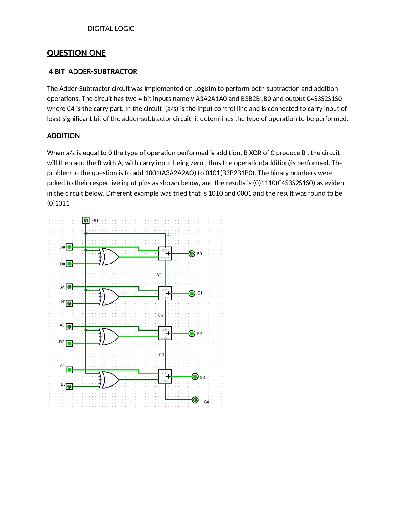
The Adder-Subtractor circuit was implemented on Logisim to perform both subtraction and addition
operations. The circuit has two 4 bit inputs namely A3A2A1A0 and B3B2B1B0 and output C4S3S2S1S0
where C4 is the carry part. In the circuit (a/s) is the input control line and is connected to carry input of
least significant bit of the adder-subtractor circuit, it determines the type of operation to be performed.
ADDITION
When a/s is equal to 0 the type of operation performed is addition, B XOR of 0 produce B , the circuit
will then add the B with A, with carry input being zero , thus the operation(addition)is performed. The
problem in the question is to add 1001(A3A2A2AO) to 0101(B3B2B1B0). The binary numbers were
poked to their respective input pins as shown below, and the results is (0)1110(C4S3S2S1S0) as evident
in the circuit below. Different example was tried that is 1010 and 0001 and the result was found to be
(0)1011

Secure Best Marks with AI Grader

Need help grading? Try our AI Grader for instant feedback on your assignments.
Document Page
DIGITAL LOGIC
SUBTRACTION
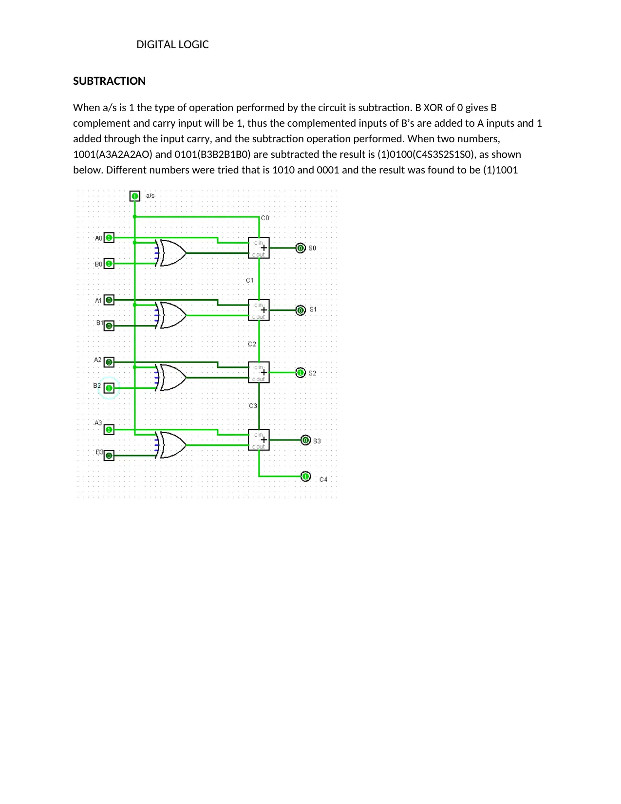
When a/s is 1 the type of operation performed by the circuit is subtraction. B XOR of 0 gives B
complement and carry input will be 1, thus the complemented inputs of B’s are added to A inputs and 1
added through the input carry, and the subtraction operation performed. When two numbers,
1001(A3A2A2AO) and 0101(B3B2B1B0) are subtracted the result is (1)0100(C4S3S2S1S0), as shown
below. Different numbers were tried that is 1010 and 0001 and the result was found to be (1)1001
Document Page
DIGITAL LOGIC
QUESTION TWO
3x8 decoder
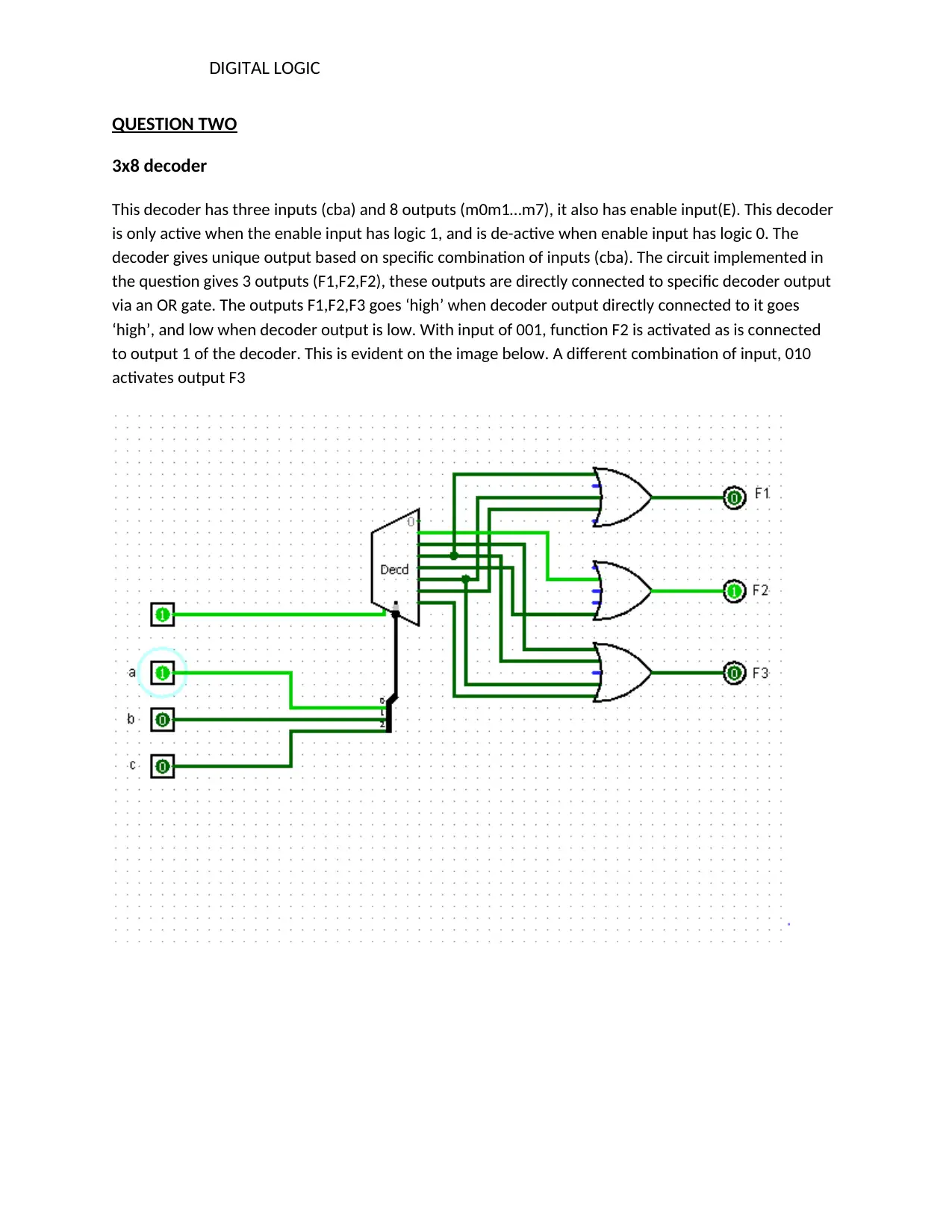
This decoder has three inputs (cba) and 8 outputs (m0m1…m7), it also has enable input(E). This decoder
is only active when the enable input has logic 1, and is de-active when enable input has logic 0. The
decoder gives unique output based on specific combination of inputs (cba). The circuit implemented in
the question gives 3 outputs (F1,F2,F2), these outputs are directly connected to specific decoder output
via an OR gate. The outputs F1,F2,F3 goes ‘high’ when decoder output directly connected to it goes
‘high’, and low when decoder output is low. With input of 001, function F2 is activated as is connected
to output 1 of the decoder. This is evident on the image below. A different combination of input, 010
activates output F3
Document Page
DIGITAL LOGIC
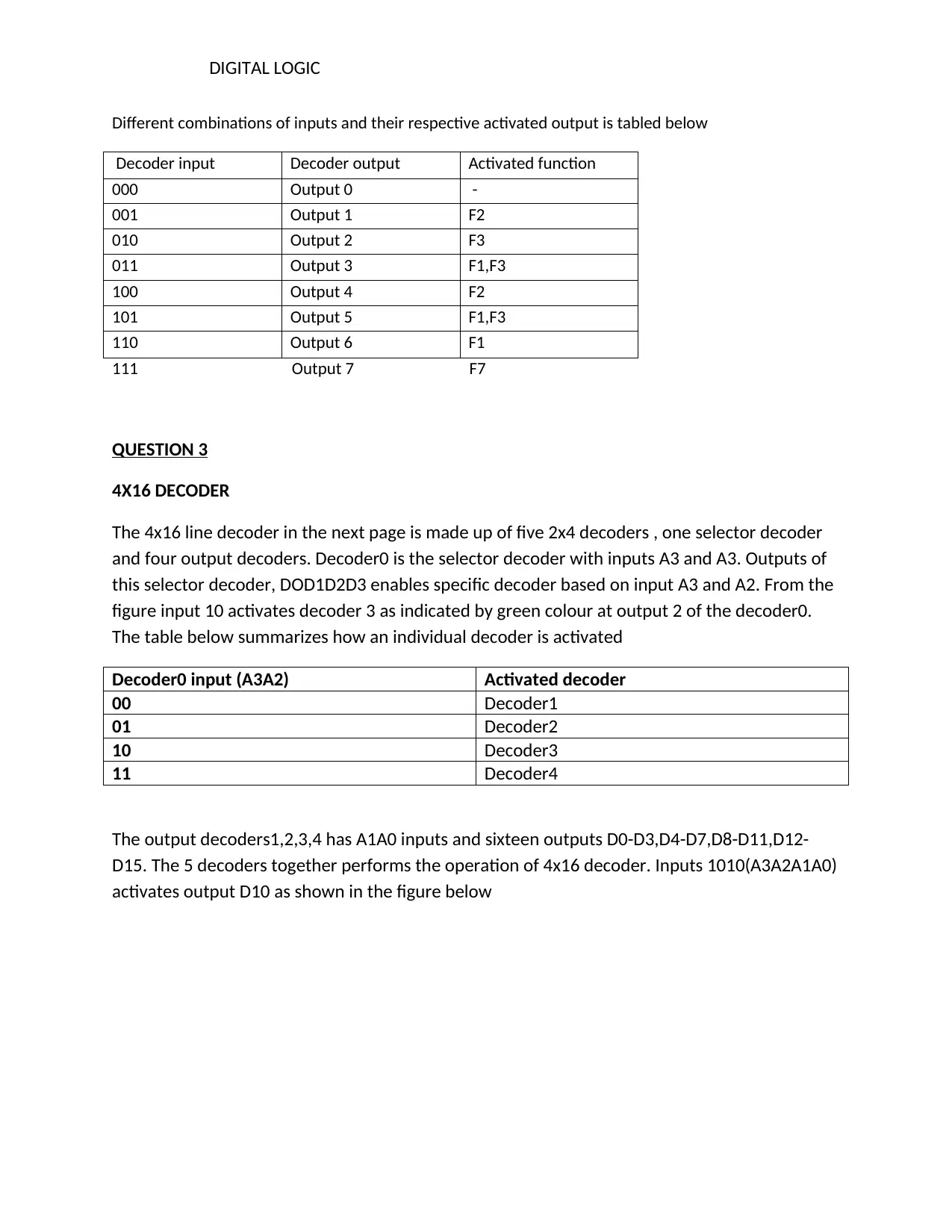
Different combinations of inputs and their respective activated output is tabled below
Decoder input Decoder output Activated function
000 Output 0 -
001 Output 1 F2
010 Output 2 F3
011 Output 3 F1,F3
100 Output 4 F2
101 Output 5 F1,F3
110 Output 6 F1
111 Output 7 F7
QUESTION 3
4X16 DECODER
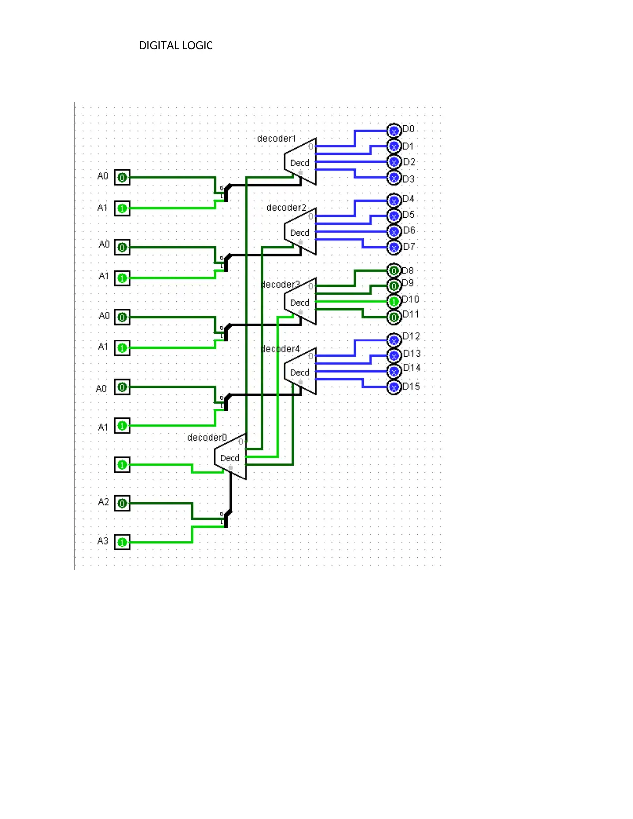
The 4x16 line decoder in the next page is made up of five 2x4 decoders , one selector decoder
and four output decoders. Decoder0 is the selector decoder with inputs A3 and A3. Outputs of
this selector decoder, DOD1D2D3 enables specific decoder based on input A3 and A2. From the
figure input 10 activates decoder 3 as indicated by green colour at output 2 of the decoder0.
The table below summarizes how an individual decoder is activated
Decoder0 input (A3A2) Activated decoder
00 Decoder1
01 Decoder2
10 Decoder3
11 Decoder4
The output decoders1,2,3,4 has A1A0 inputs and sixteen outputs D0-D3,D4-D7,D8-D11,D12-
D15. The 5 decoders together performs the operation of 4x16 decoder. Inputs 1010(A3A2A1A0)
activates output D10 as shown in the figure below

Paraphrase This Document

Need a fresh take? Get an instant paraphrase of this document with our AI Paraphraser
Document Page
DIGITAL LOGIC
Document Page
DIGITAL LOGIC
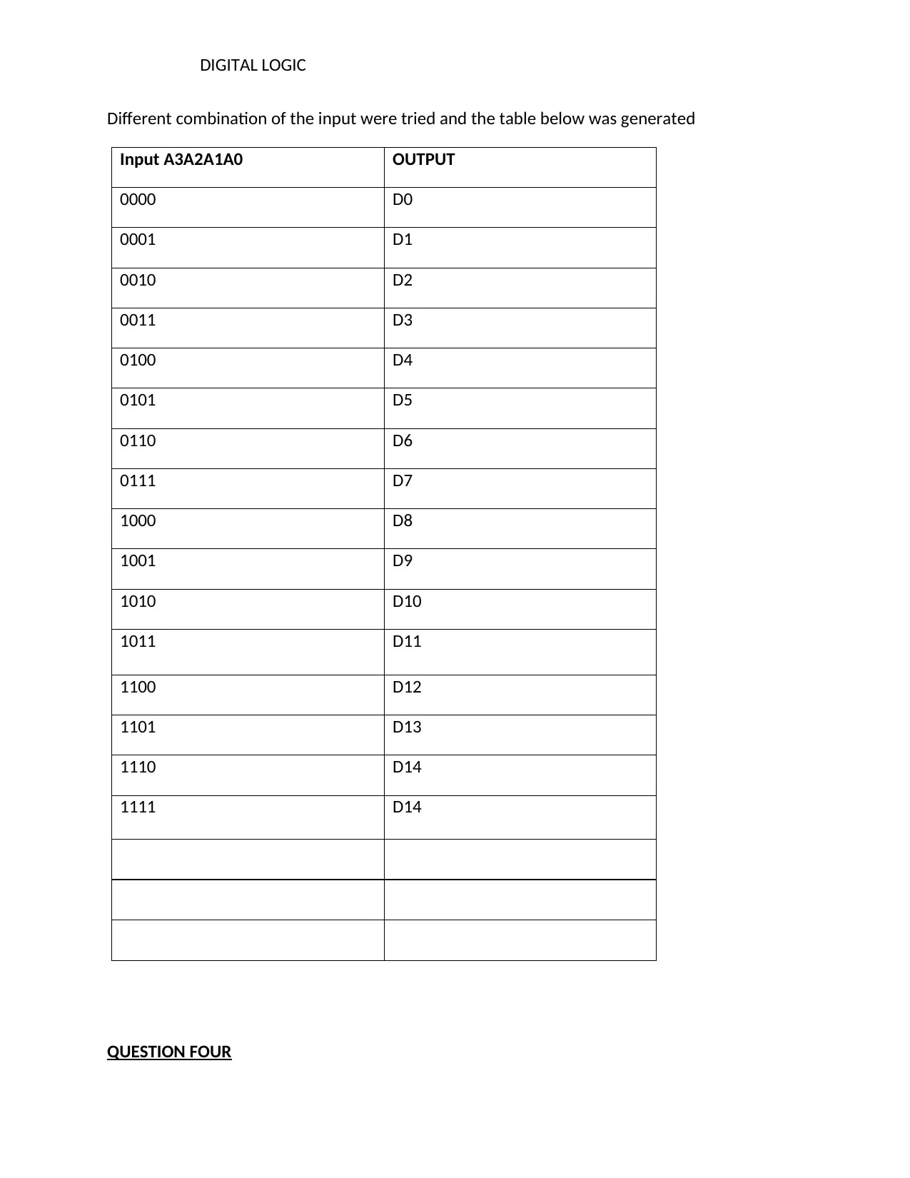
Different combination of the input were tried and the table below was generated
Input A3A2A1A0 OUTPUT
0000 D0
0001 D1
0010 D2
0011 D3
0100 D4
0101 D5
0110 D6
0111 D7
1000 D8
1001 D9
1010 D10
1011 D11
1100 D12
1101 D13
1110 D14
1111 D14
QUESTION FOUR
Document Page
DIGITAL LOGIC
8 to 1 multiplexer
a)
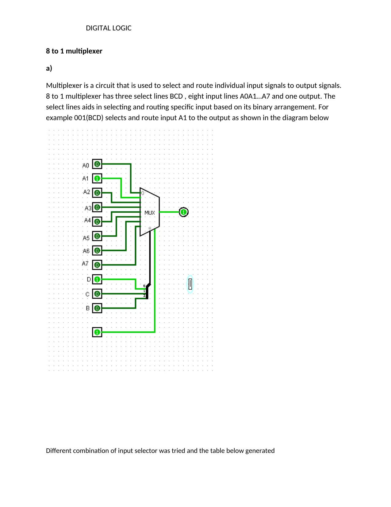
Multiplexer is a circuit that is used to select and route individual input signals to output signals.
8 to 1 multiplexer has three select lines BCD , eight input lines A0A1…A7 and one output. The
select lines aids in selecting and routing specific input based on its binary arrangement. For
example 001(BCD) selects and route input A1 to the output as shown in the diagram below
Different combination of input selector was tried and the table below generated

Secure Best Marks with AI Grader

Need help grading? Try our AI Grader for instant feedback on your assignments.
Document Page
DIGITAL LOGIC
Select lines (BCD) Selected input
000 A0
001 A1
010 A2
011 A3
100 A4
101 A5
110 A6
111 A7
b)
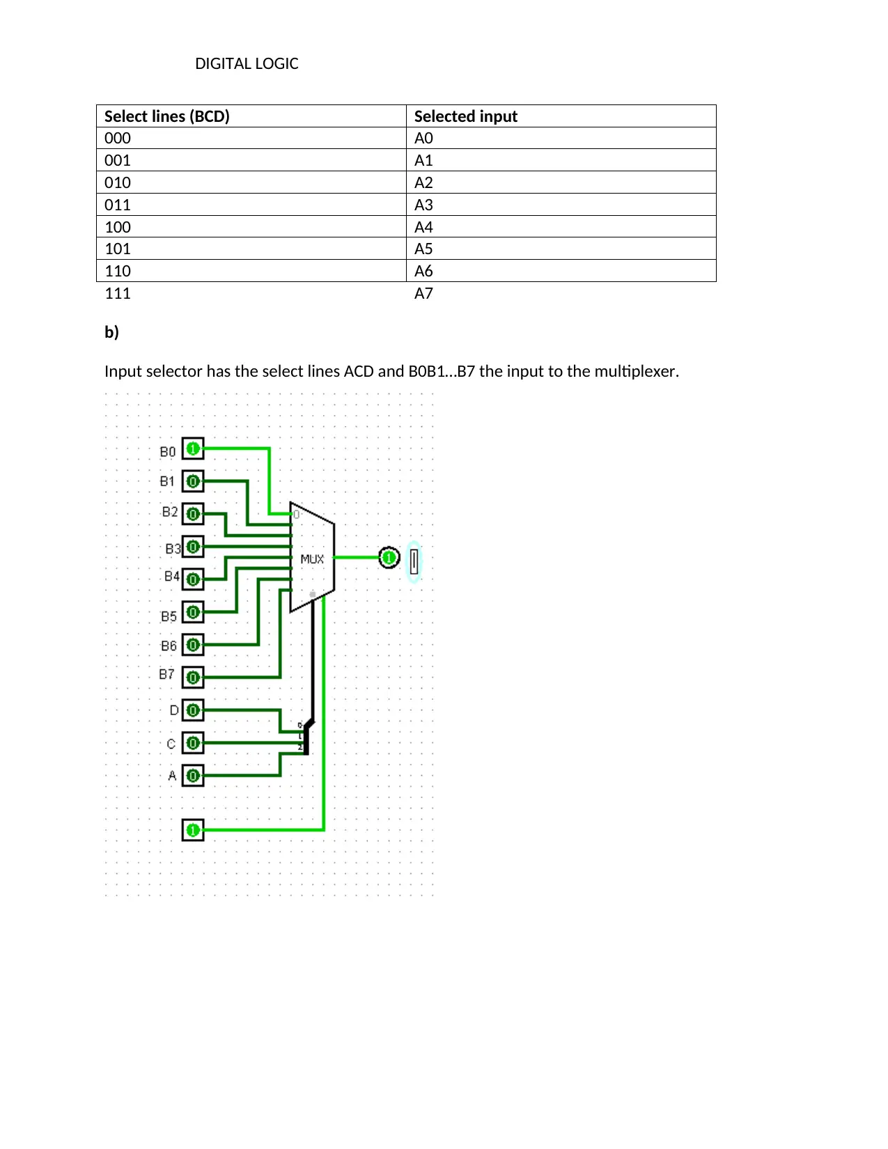
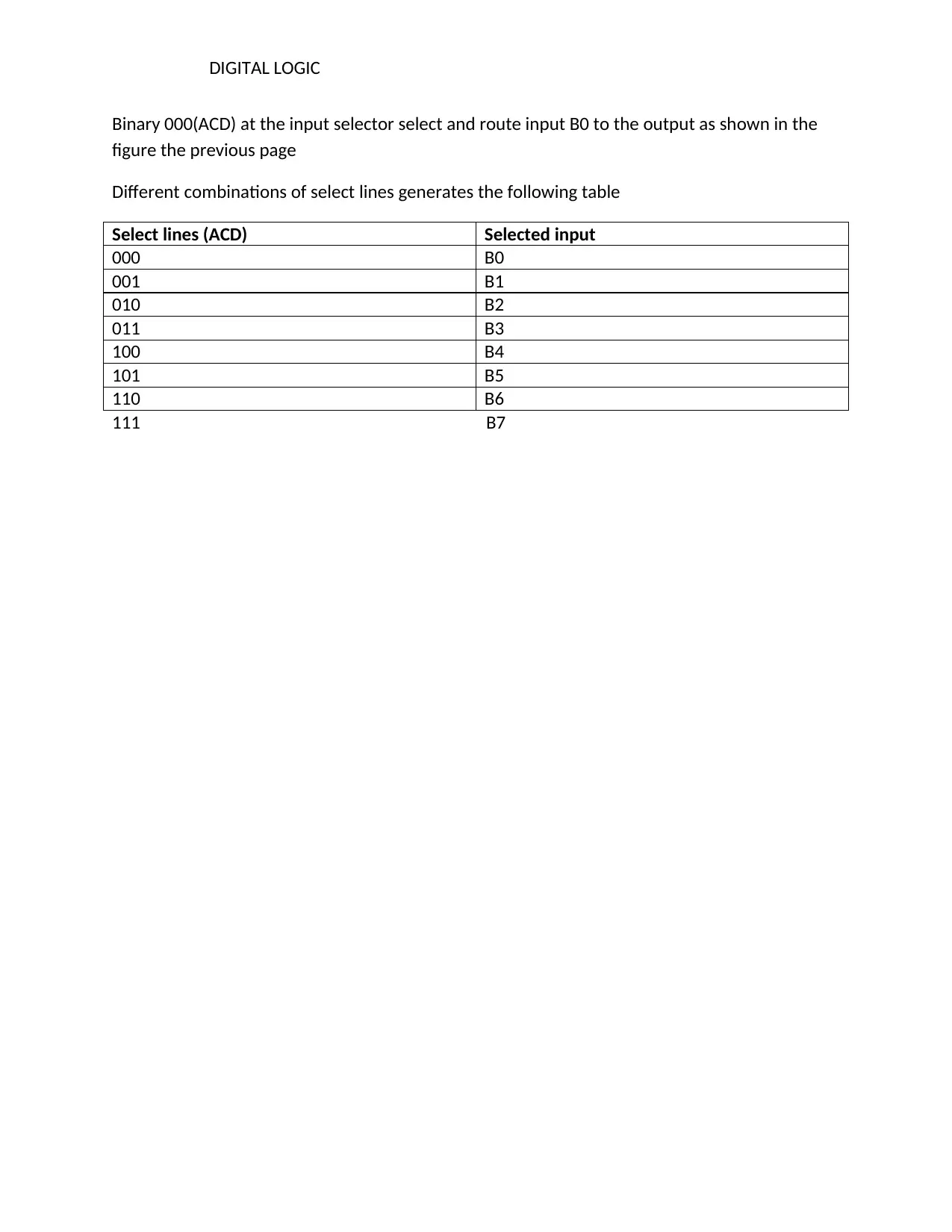
Input selector has the select lines ACD and B0B1…B7 the input to the multiplexer.
Document Page
DIGITAL LOGIC
Binary 000(ACD) at the input selector select and route input B0 to the output as shown in the
figure the previous page
Different combinations of select lines generates the following table
Select lines (ACD) Selected input
000 B0
001 B1
010 B2
011 B3
100 B4
101 B5
110 B6
111 B7
Document Page
DIGITAL LOGIC
REFERENCES
Mano, M. M. (2017). Digital logic and computer design. Pearson Education India.
Roth Jr, C., & Kinney, L. (2013). Fundamentals of logic design. Nelson Education.
1 out of 10
[object Object]

Your All-in-One AI-Powered Toolkit for Academic Success.

Available 24*7 on WhatsApp / Email

[object Object]