Electric Motor Design: Principles, Operation, and Design
VerifiedAdded on 2023/04/08
|9
|1295
|458
Report
AI Summary
This report provides a detailed overview of electric motor design, focusing on the principles of operation and practical implementation. It begins by explaining the fundamental concepts of electromagnetism and how they relate to motor function, referencing Fleming's Left-Hand Rule to illustrate the direction of motion. The report distinguishes between AC and DC motor operation, highlighting the role of the commutator in DC motors. A step-by-step guide to designing a simple electric motor is included, detailing the materials used (such as a battery, wires, and magnets) and the assembly process. Observations from the design process are discussed, including the importance of correct polarity and insulation removal for continuous rotation. The report concludes that the motor design was successful, while also noting potential improvements such as using a higher capacity battery or a stronger magnet to enhance efficiency. The report also references several works on electric motors and energy efficiency.
Running Head: ELECTRIC MOTOR DESIGN 1
ELECTRIC MOTOR DESIGN
Students’ name
Institution affiliation
ELECTRIC MOTOR DESIGN
Students’ name
Institution affiliation
Paraphrase This Document
Need a fresh take? Get an instant paraphrase of this document with our AI Paraphraser
Electric Motor Design 2
Executive Summary
There exists many forms of energy. One form can be converted into the other, depending on the
area of application. This report focuses on the operation and design of motors which utilizes
electrical energy to produce mechanical energy in form of motion. The principle of operation of
electric motors is explained first by looking at the discovery of Fleming whose name was later
used to refer to the motor rule that explains how direction of motion of a motor can be
determined (Flemings’ Left Hand Rule). The operation of a motor using AC and DC is also
explained hence the understanding of why a commutator is employed in motors. The design of a
simple motor is explained, observations and conclusions are then made.
Electric Motor Design 3
Table of Contents
Executive Summary.....................................................................................................................................2
INTRODUCTION...........................................................................................................................................4
MATERIALS USED.........................................................................................................................................5
PROCEDURE.................................................................................................................................................5
OBSERVATIONS AND DISCUSSIONS.............................................................................................................7
CONCLUSION...............................................................................................................................................8
References...................................................................................................................................................9
⊘ This is a preview!⊘
Do you want full access?
Subscribe today to unlock all pages.

Trusted by 1+ million students worldwide
Electric Motor Design 4
INTRODUCTION
Electric motors are machines that are used to produce mechanical energy or work by
employing the conversion of electric energy. This is made possible by the interaction of a
permanent magnetic field and current (the flow of electrons) also known as electromagnetic
interaction/electromagnetism (Hughes & Drury , 2013). The operation of motors can be traced
back to Michael Faraday’s initial design in 1831 when he came up with the concept of a current
carrying conductor placed in a magnetic field experiences a force equal to the current passing
through it and the field strength. The direction of motion can be figured out by using a memory
aid also known as the Motor rule (Flemings Left-Hand Rule) where the thumb and first two
fingers of the left hand are held pointed out such that they are at right angles to each other. The
first finger should point out to the direction of field (flowing from North to South) the second
finger should point towards the direction of current flow (positive to negative terminal of the
battery) then the thumb should be pointing to the direction of motion (Force) (Fujitaki, 2009).
The conductors are many turns of wires forming a winding that will directly correspond
to the force of electromagnetism. More torque (Force) will be experienced when there is more
current passing through the windings (Parasilit & Paolo, 2012). Another way would be to
increase the number of windings on the coil instead of using a single thick wire. In practice, the
permanent magnet is round so that it almost touches the windings on the coil hence increasing
the force produced by the motor (Jordan, 2013). The ultimate goal, motion, is therefore realized
when two magnets act on each other, one on the stator (the permanent magnet), and the other on
the rotor (magnet formed on current carrying conductor) act on each other. The rotor usually has
a commutator on its end, a half-metal ring, whose function is to reverse the direction of current
in the coil each time a half turn is made by the coil (Bertoldi, Falkner, & de Almeida, 2012). This
Paraphrase This Document
Need a fresh take? Get an instant paraphrase of this document with our AI Paraphraser
Electric Motor Design 5
ensures that the coil maintains motion in one direction, otherwise the coil would move in the
opposite direction after each half turn.
MATERIALS USED
Electric motors can be driven by either DC or AC. The latter doesn’t need a commutator
in place since it alternates the direction of flow of current. This leaves the use of a commutator
with DC (Hand, 2011), which will be the source of power in the design of the motor covered in
this report. The aim is to come up with a simple electric motor using the materials provided
which include:
One block of wood with attached magnet
Two paper clips
Battery holders
Wires
1.5 V battery (self-provided)
Marker (self-provided)
Pen knife (self-provided)
Tape
PROCEDURE
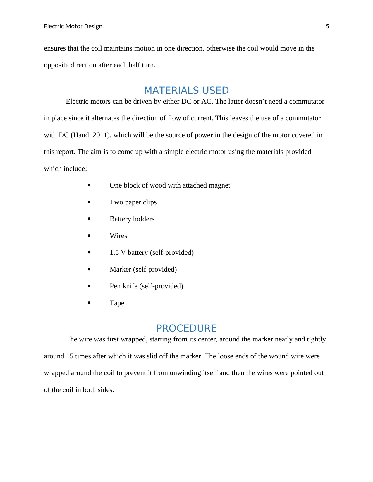
The wire was first wrapped, starting from its center, around the marker neatly and tightly
around 15 times after which it was slid off the marker. The loose ends of the wound wire were
wrapped around the coil to prevent it from unwinding itself and then the wires were pointed out
of the coil in both sides.
Electric Motor Design 6
Figure 1 Wound coil
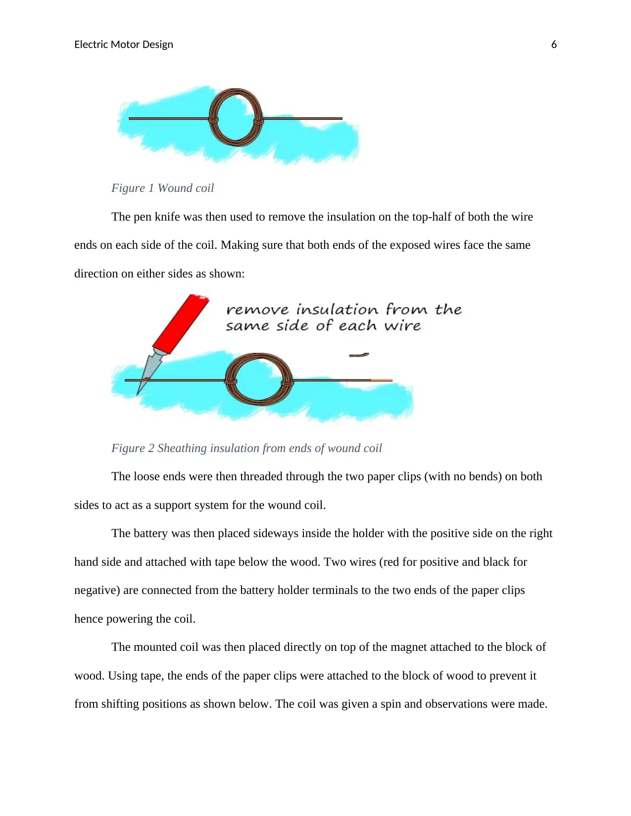
The pen knife was then used to remove the insulation on the top-half of both the wire
ends on each side of the coil. Making sure that both ends of the exposed wires face the same
direction on either sides as shown:
Figure 2 Sheathing insulation from ends of wound coil
The loose ends were then threaded through the two paper clips (with no bends) on both
sides to act as a support system for the wound coil.
The battery was then placed sideways inside the holder with the positive side on the right
hand side and attached with tape below the wood. Two wires (red for positive and black for
negative) are connected from the battery holder terminals to the two ends of the paper clips
hence powering the coil.
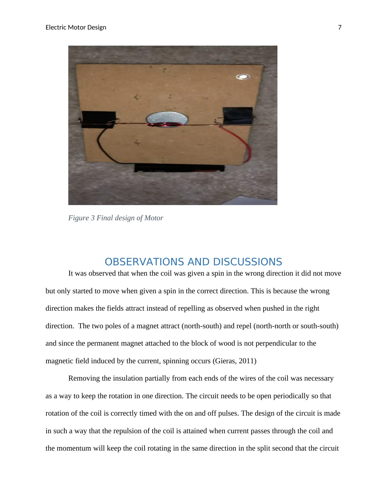
The mounted coil was then placed directly on top of the magnet attached to the block of
wood. Using tape, the ends of the paper clips were attached to the block of wood to prevent it
from shifting positions as shown below. The coil was given a spin and observations were made.
⊘ This is a preview!⊘
Do you want full access?
Subscribe today to unlock all pages.

Trusted by 1+ million students worldwide
Electric Motor Design 7
Figure 3 Final design of Motor
OBSERVATIONS AND DISCUSSIONS
It was observed that when the coil was given a spin in the wrong direction it did not move
but only started to move when given a spin in the correct direction. This is because the wrong
direction makes the fields attract instead of repelling as observed when pushed in the right
direction. The two poles of a magnet attract (north-south) and repel (north-north or south-south)
and since the permanent magnet attached to the block of wood is not perpendicular to the
magnetic field induced by the current, spinning occurs (Gieras, 2011)
Removing the insulation partially from each ends of the wires of the coil was necessary
as a way to keep the rotation in one direction. The circuit needs to be open periodically so that
rotation of the coil is correctly timed with the on and off pulses. The design of the circuit is made
in such a way that the repulsion of the coil is attained when current passes through the coil and
the momentum will keep the coil rotating in the same direction in the split second that the circuit
Paraphrase This Document
Need a fresh take? Get an instant paraphrase of this document with our AI Paraphraser
Electric Motor Design 8
is off until contact of the circuit is achieved where the current takes over the spinning (Stuart,
2013).
CONCLUSION
The design of the simple motor was a success. The main aim was to achieve the rotation
of the wound coil using a single 1.5V battery. However, the efficiency could be improved by
using a battery of large capacity or a magnet of greater magnitude.
Electric Motor Design 9
References
Bertoldi, P., Falkner, H., & de Almeida, A. T. (2012). Energy Efficiency Improvements in Electronic Motors
and Drives. Berlin: Springer Science & Business Media.
Fujitaki, K. (2009). The Manga Guide to Electricity. California : No Starch Press.
Gieras, J. F. (2011). Permanent Magnet Motor Technology: Design and Applications, Third Edition. CRC
Press: Florida.
Hand, A. (2011). Electric Motor Maintenance and Troubleshooting. Pennsylvania: McGraw Hill
Professional.
Hughes , A., & Drury , W. (2013). Electric Motors and Drives: Fundamentals, Types and Applications.
Wales : Newnes.
Jordan, H. E. (2013). Energy-Efficient Electric Motors and their Applications. Berlin: Springer Science &
Business Media.
Parasilit, F., & Paolo, B. (2012). Energy Efficiency in Motor Driven Systems. Berlin: Springer Science &
Business Media.
Stuart, S. (2013). DC Motors, Speed Controls, Servo Systems. Amsterdam: Elsevier.
⊘ This is a preview!⊘
Do you want full access?
Subscribe today to unlock all pages.

Trusted by 1+ million students worldwide
1 out of 9
Related Documents
Your All-in-One AI-Powered Toolkit for Academic Success.
+13062052269
info@desklib.com
Available 24*7 on WhatsApp / Email
![[object Object]](/_next/static/media/star-bottom.7253800d.svg)
Unlock your academic potential
Copyright © 2020–2026 A2Z Services. All Rights Reserved. Developed and managed by ZUCOL.


