Electrical and Electronic Principles: Sensor Circuit Design, Logic Design, and A.C. Load Supply
Verified
Added on  2023/06/09
|7
|766
|321
AI Summary
This article discusses the design of sensor circuits, logic circuits, and A.C. load supply in Electrical and Electronic Principles. It includes Boolean expressions, Logisim circuits, and testing.
Contribute Materials
Your contribution can guide someone’s learning journey. Share your
documents today.
Running head: ELECTRICAL AND ELECTRONIC PRINCIPLES EAT119 Electrical and Electronic Principles Name of the Student University of Sunderland Author Note
Secure Best Marks with AI Grader
Need help grading? Try our AI Grader for instant feedback on your assignments.
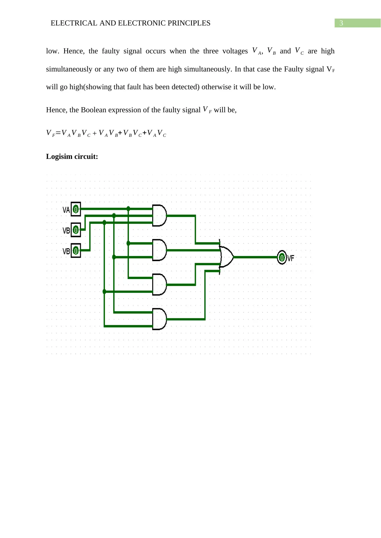
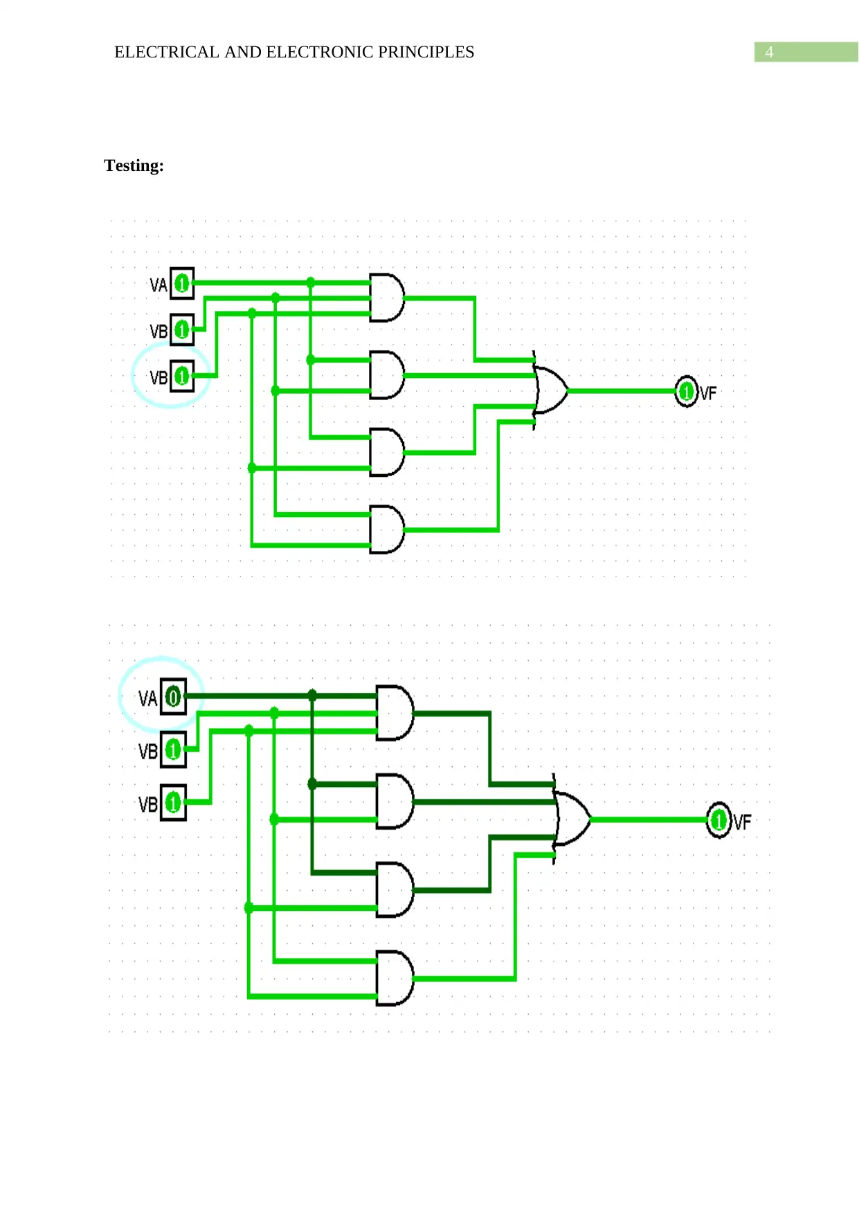
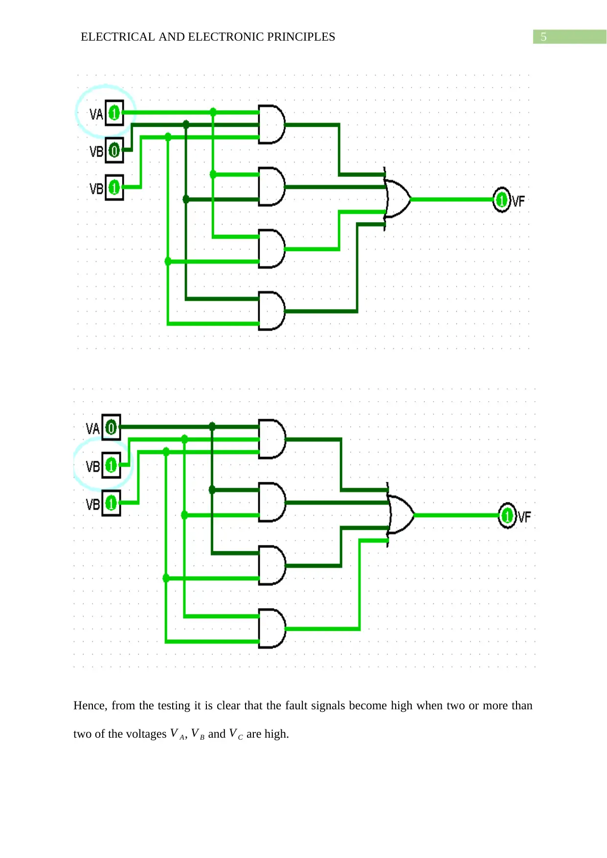
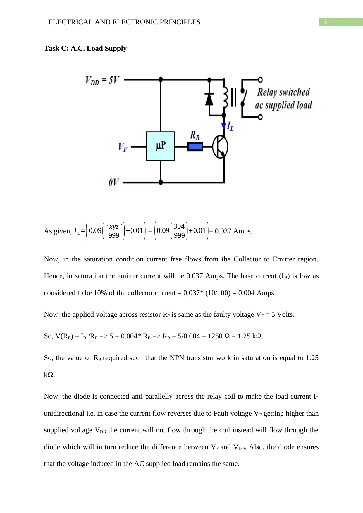
3ELECTRICAL AND ELECTRONIC PRINCIPLES low. Hence, the faulty signal occurs when the three voltagesVA,VBandVCare high simultaneously or any two of them are high simultaneously. In that case the Faulty signal VF will go high(showing that fault has been detected) otherwise it will be low. Hence, the Boolean expression of the faulty signalVFwill be, VF=VAVBVC+VAVB+VBVC+VAVC Logisim circuit:
Paraphrase This Document
Need a fresh take? Get an instant paraphrase of this document with our AI Paraphraser
5ELECTRICAL AND ELECTRONIC PRINCIPLES Hence, from the testing it is clear that the fault signals become high when two or more than two of the voltagesVA,VBandVCare high.