Electrical Circuit Safety and Analysis
VerifiedAdded on 2020/05/11
|13
|2092
|89
AI Summary
The assignment delves into crucial aspects of electrical circuits, emphasizing safety protocols like grounding and safe isolation techniques to prevent electrocution and equipment damage. It explains the importance of Residual Current Devices (RCDs) and Ground Fault Interrupters (GFIs) in safeguarding against fatal shocks. Furthermore, it elucidates key oscilloscope parameters such as resolution, bandwidth, and sensitivity, highlighting their significance in accurate waveform measurement and analysis.
Contribute Materials
Your contribution can guide someone’s learning journey. Share your
documents today.

Running head: Electronics measure and test
1
Electronics measure and test
Author
Course: Electronics
Date
1
Electronics measure and test
Author
Course: Electronics
Date
Secure Best Marks with AI Grader
Need help grading? Try our AI Grader for instant feedback on your assignments.
Electronics measure and test
2
Task 1A
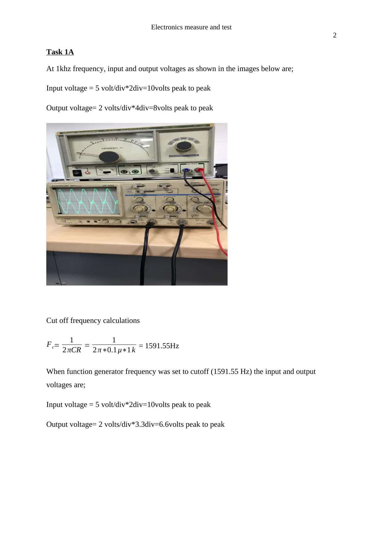
At 1khz frequency, input and output voltages as shown in the images below are;
Input voltage = 5 volt/div*2div=10volts peak to peak
Output voltage= 2 volts/div*4div=8volts peak to peak
Cut off frequency calculations
Fc= 1
2 πCR = 1
2 π∗0.1 μ∗1 k = 1591.55Hz
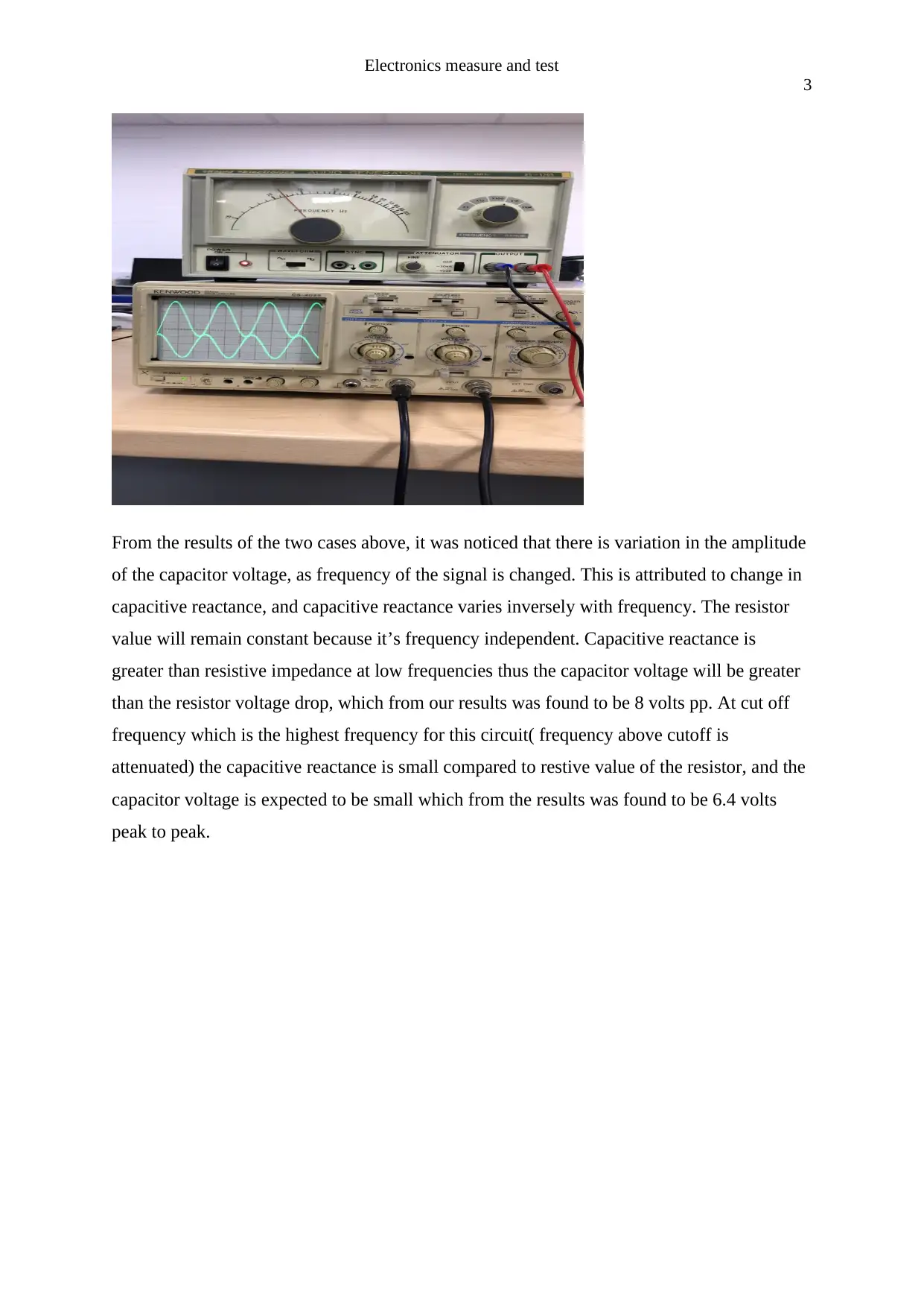
When function generator frequency was set to cutoff (1591.55 Hz) the input and output
voltages are;
Input voltage = 5 volt/div*2div=10volts peak to peak
Output voltage= 2 volts/div*3.3div=6.6volts peak to peak
Electronics measure and test
3
From the results of the two cases above, it was noticed that there is variation in the amplitude
of the capacitor voltage, as frequency of the signal is changed. This is attributed to change in
capacitive reactance, and capacitive reactance varies inversely with frequency. The resistor
value will remain constant because it’s frequency independent. Capacitive reactance is
greater than resistive impedance at low frequencies thus the capacitor voltage will be greater
than the resistor voltage drop, which from our results was found to be 8 volts pp. At cut off
frequency which is the highest frequency for this circuit( frequency above cutoff is
attenuated) the capacitive reactance is small compared to restive value of the resistor, and the
capacitor voltage is expected to be small which from the results was found to be 6.4 volts
peak to peak.
Electronics measure and test
4
Task 1B
1)
Time constant (τ ) = RC
Chosen resistor value is 10Kohms and capacitor value is 470uF
τ =10000*470*10^-6
=4.7
Time at which capacitor voltage will be 90% of maximum value is
-t=4.7{exp(1-(0.9*12)/12)}=10.8secs
Time at which capacitor voltage will be 90% of maximum value is
-t=4.7{exp(1-(0.1*12)/12)}=1.72secs
2)
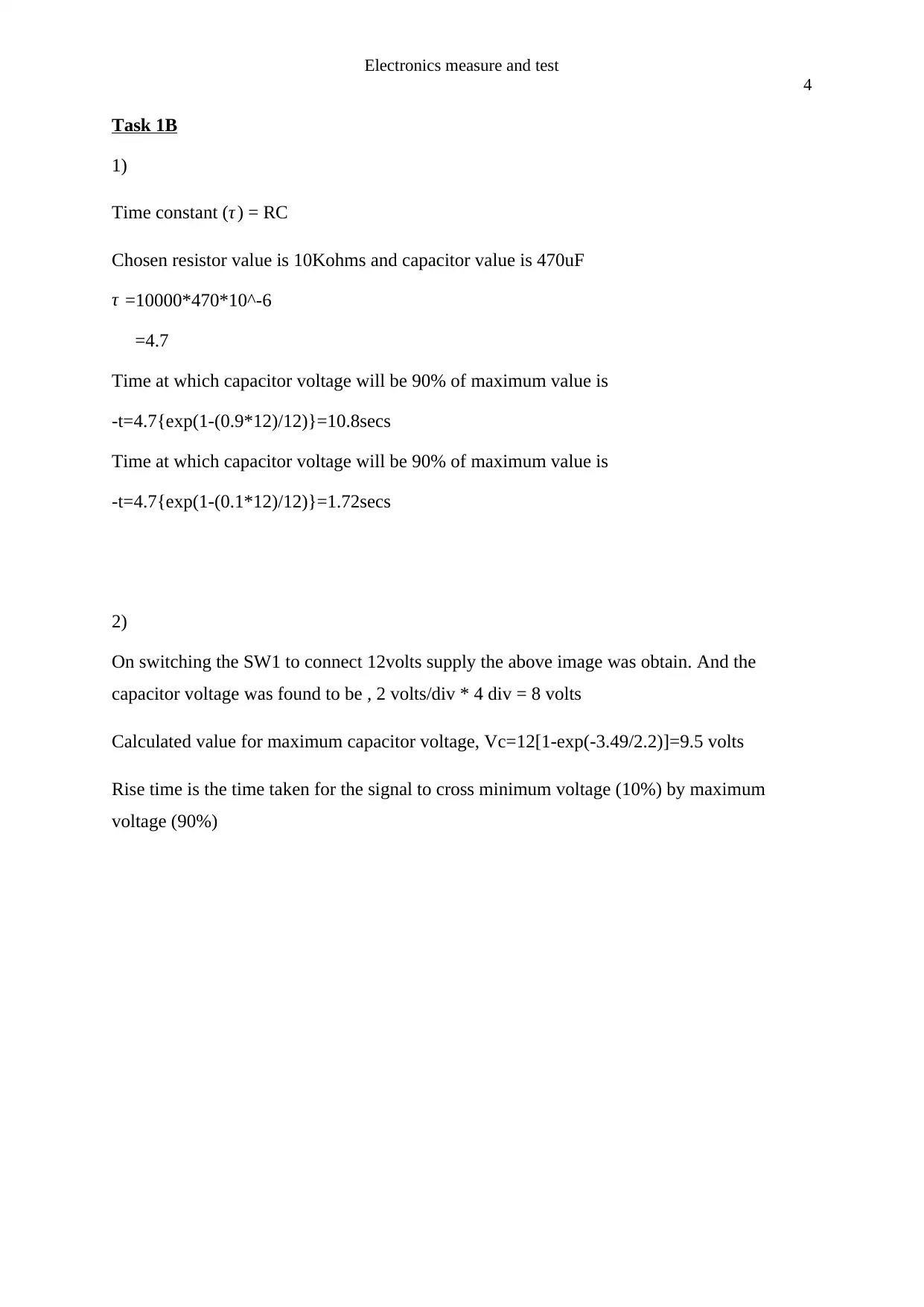
On switching the SW1 to connect 12volts supply the above image was obtain. And the
capacitor voltage was found to be , 2 volts/div * 4 div = 8 volts
Calculated value for maximum capacitor voltage, Vc=12[1-exp(-3.49/2.2)]=9.5 volts
Rise time is the time taken for the signal to cross minimum voltage (10%) by maximum
voltage (90%)
Secure Best Marks with AI Grader
Need help grading? Try our AI Grader for instant feedback on your assignments.
Electronics measure and test
5
3)
Rise time is the time taken for the signal to cross minimum voltage (10%) by maximum
voltage (90%) T(rise)=T(90%)-T(10%)
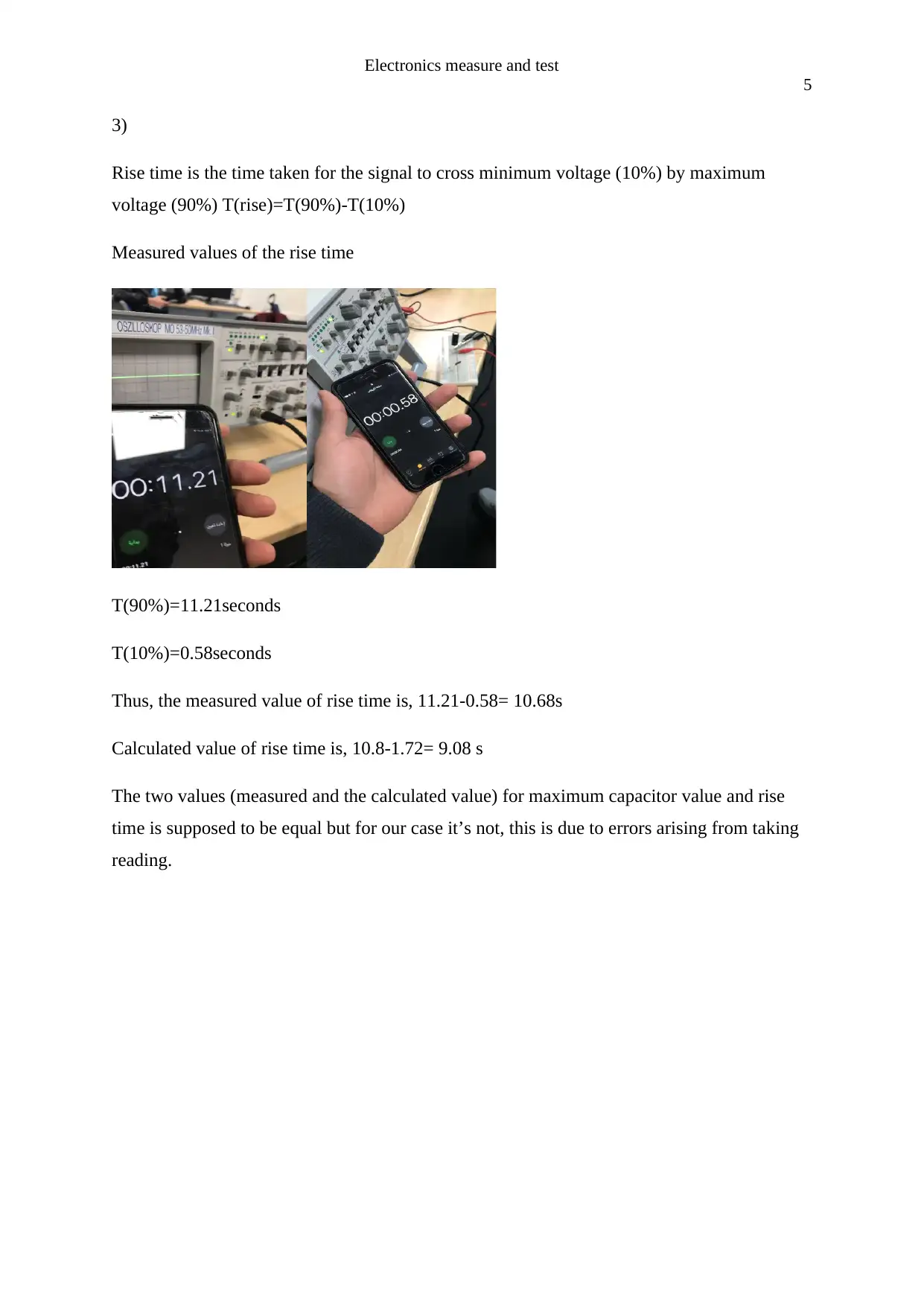
Measured values of the rise time
T(90%)=11.21seconds
T(10%)=0.58seconds
Thus, the measured value of rise time is, 11.21-0.58= 10.68s
Calculated value of rise time is, 10.8-1.72= 9.08 s
The two values (measured and the calculated value) for maximum capacitor value and rise
time is supposed to be equal but for our case it’s not, this is due to errors arising from taking
reading.
Electronics measure and test
6
Task 1 C
The objective of the task was to determine the unknown internal resistance of a 9V battery
using two multi-meters and applying Ohm's law.
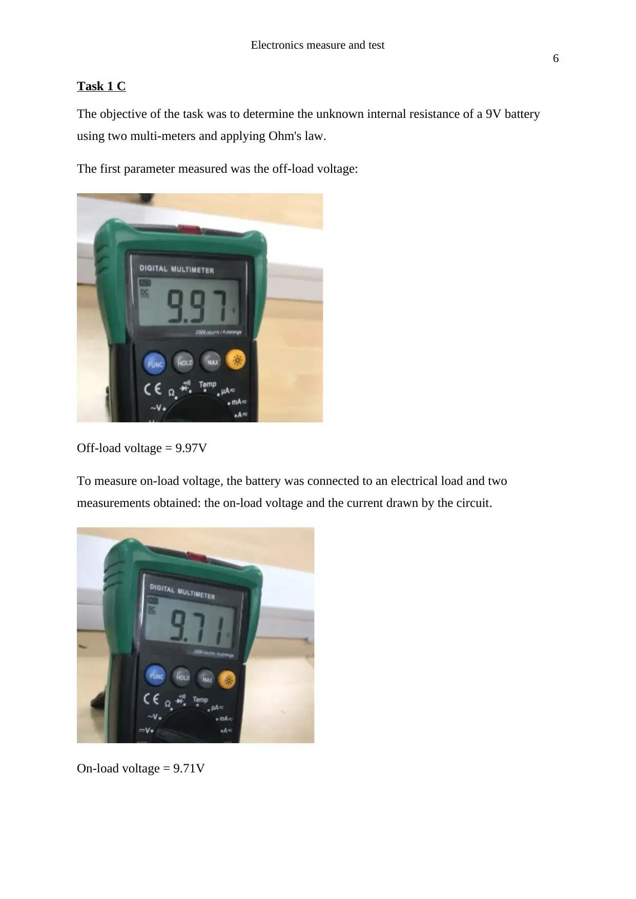
The first parameter measured was the off-load voltage:
Off-load voltage = 9.97V
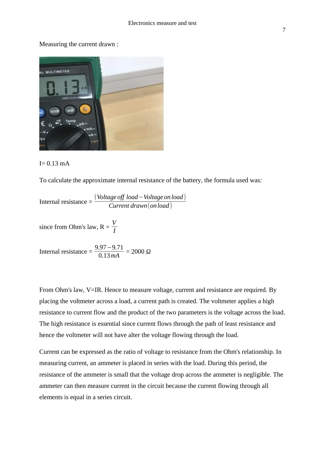
To measure on-load voltage, the battery was connected to an electrical load and two
measurements obtained: the on-load voltage and the current drawn by the circuit.
On-load voltage = 9.71V
Electronics measure and test
7
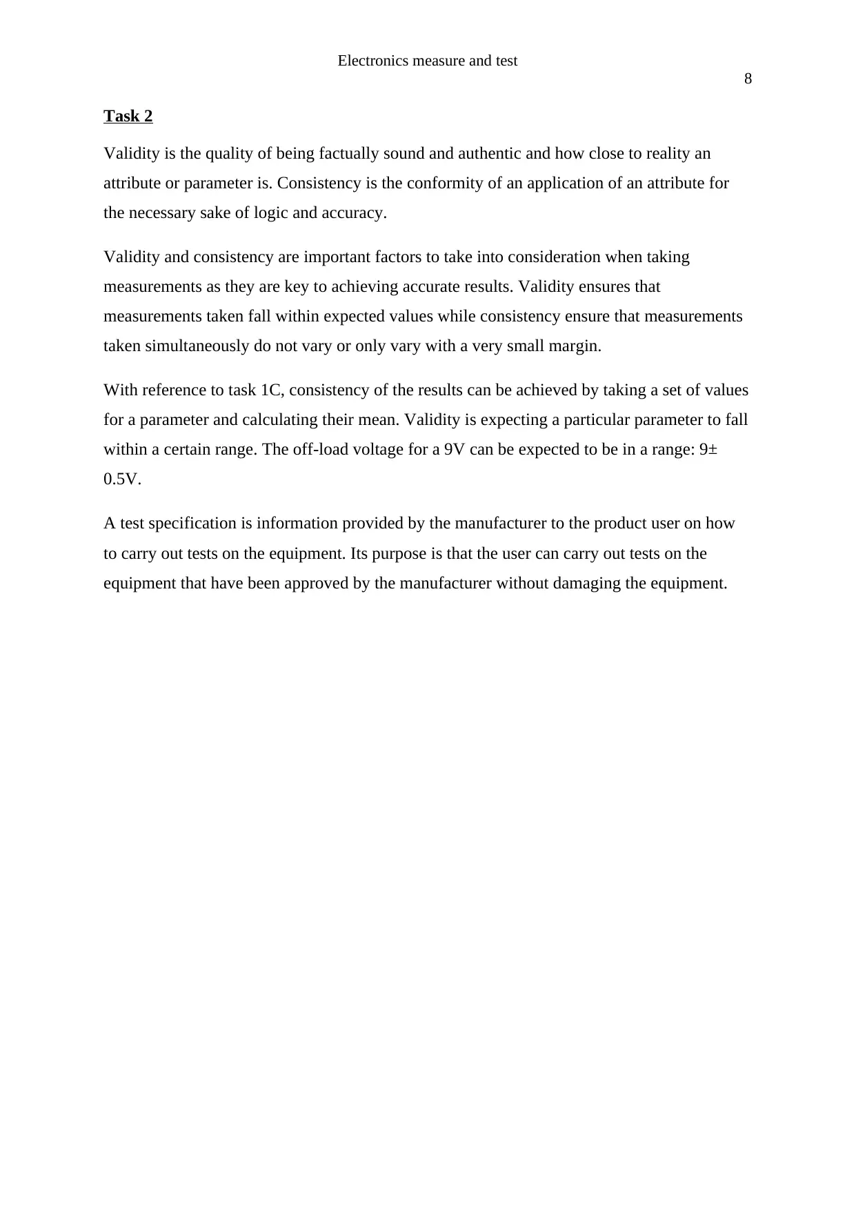
Measuring the current drawn :
I= 0.13 mA
To calculate the approximate internal resistance of the battery, the formula used was:
Internal resistance = (Voltage off load−Voltage on load)
Current drawn(on load)
since from Ohm's law, R = V
I
Internal resistance = 9.97−9.71
0.13 mA = 2000 Ω
From Ohm's law, V=IR. Hence to measure voltage, current and resistance are required. By
placing the voltmeter across a load, a current path is created. The voltmeter applies a high
resistance to current flow and the product of the two parameters is the voltage across the load.
The high resistance is essential since current flows through the path of least resistance and
hence the voltmeter will not have alter the voltage flowing through the load.
Current can be expressed as the ratio of voltage to resistance from the Ohm's relationship. In
measuring current, an ammeter is placed in series with the load. During this period, the
resistance of the ammeter is small that the voltage drop across the ammeter is negligible. The
ammeter can then measure current in the circuit because the current flowing through all
elements is equal in a series circuit.
Paraphrase This Document
Need a fresh take? Get an instant paraphrase of this document with our AI Paraphraser
Electronics measure and test
8
Task 2
Validity is the quality of being factually sound and authentic and how close to reality an
attribute or parameter is. Consistency is the conformity of an application of an attribute for
the necessary sake of logic and accuracy.
Validity and consistency are important factors to take into consideration when taking
measurements as they are key to achieving accurate results. Validity ensures that
measurements taken fall within expected values while consistency ensure that measurements
taken simultaneously do not vary or only vary with a very small margin.
With reference to task 1C, consistency of the results can be achieved by taking a set of values
for a parameter and calculating their mean. Validity is expecting a particular parameter to fall
within a certain range. The off-load voltage for a 9V can be expected to be in a range: 9±
0.5V.
A test specification is information provided by the manufacturer to the product user on how
to carry out tests on the equipment. Its purpose is that the user can carry out tests on the
equipment that have been approved by the manufacturer without damaging the equipment.
Electronics measure and test
9
Task 3
Calibration in the field of testing and measurement field is the comparison between standard
measurement value provided by the manufacturer and measurement obtained from the said
instrument, and also includes repair of equipment that is out of calibration. While the
calibration standard is more accurate than the equipment under test, the accuracy ratio must
be small. Manufactures provides a report of an equipment done by calibration experts at
accredited laboratories, and this report show the measurement error the measuring instrument
has before and after the calibration, accuracy is given a priority.
It’s important that calibration is done as failure to do so ,pose quite number of risks. One risk
is safety risk, in electrical systems for example , uncalibrated equipment may create a risk of
electrical shock to human beings around the surrounding. Uncalibrated equipment waste raw
materials and resources, it also waste one’s time and manpower and this can lead to big loss,
which will cost you a lot. Uncalibrated equipment also compromises the quality of
production, thus calibrating instruments keep the quality in check. And finally by calibrating
your equipment you helping in reducing downtime and avoiding disruptions to your schedule
On when to calibrate your equipment there are quite number of factors to consider. One,
manufacturer’s specification on the interval you are recommended to calibrate your
instruments. You are also recommended to calibrate your equipment before and after using
where more accurate measurements is required. You also recommended to take your
equipment for calibration after a hit, physical impact, an overload or any other accident.
Some projects require you to calibrate your equipment before the test, this forces you to
perform one.
In dry and cold air, measurement by instruments is nearly equal to standard measurement ,
while measurement by instrument in the humidified and warmed air gives higher deviation
from the standard value as compared to the dry and cold air.
Electronics measure and test
10
Task 4
Steps for testing a direct online starters are:
i. Isolate the starter from external connections.
ii. Conduct an insulation resistance between the three-phase terminals to ensure no
continuity between the phases.
iii. Check for no continuity between each phase input and its output as the contactor coil
is not energized.
iv. Check the coil rating and its wiring.
v. Check the overload is set correctly for the motor it operates.
vi. Energize the contactor coil to check its operation. Pressing the ON (green) button
energizes the contactor coil. Check that there is continuity for each set of phases.
Press the OFF(red) button and observe that the contactor de-energizes.
vii. Test for continuity in the motor cables. Carry the insulation resistance to ensure the
motor connection is correct.
viii. Check the fuses are suitable at the miniature circuit breaker(MCB).
ix. Connect the 3∅ supply and the motor cables to the direct online starter and confirm if
working appropriately.
Some precautions taken while working on live circuits are checking for damaged insulation
on the cables. This could be sources of electrocution and short-circuit faults. While working
on live circuits, care should be taken by using well insulated tools and testers to check for live
circuits before any operation on them. The circuit breakers should also be correctly rated for
them to trip in the event of a short circuit or over-current in the circuit to prevent damage to
the equipment.
Benefits of grounding electrical equipment is mainly due to protecting people from extensive
damage due to electrocution. It also protects equipment from surges as excessive currents will
flow to the ground.
Safe isolation techniques are regulations used to guide maintenance and repair procedures for
any electrical installation . The first step is to identify the correct point of isolation which
should also not be inadvertently reinstated while work is ongoing. To ensure that other
personnel do not interfere with the isolation point, a few steps can be taken:
Secure Best Marks with AI Grader
Need help grading? Try our AI Grader for instant feedback on your assignments.
Electronics measure and test
11
isolation of individual circuits protected by fuses and utilizing lockable fuse inserts
or replacement of fuse with a dummy fuse.
isolation at main switch or the distribution board.
temporary disconnection of the incoming supply.
Electrical safety cut-outs such as Residue Current Devices(RCDs) and Ground Fault
Interrupters(GFIs) are important as they protect from fatal electric shocks. RCDs are
designed to work by breaking the incoming circuit cables thereby stopping current flow when
they detect current imbalance between the live and neutral cables. The GFI works on the
principle of current imbalance between the hot and neutral wires. This imbalance indicates an
abnormal current diversion from the hot wire as in the case of electrocution and current
leakage and in this scenario it trips the breaker.
Task 5

Electronics measure and test
12
The resolution of an oscilloscope is defined as how precisely the scope can measure the input.
The two parameters required to achieve as suitable waveform are resolution and dynamic
range as they are essential in obtaining a waveform that is not clipped. The ability of the
scope to indicate how the vertical system amplifies or attenuates a signal is the gain accuracy.
The vertical sensitivity is the ability of the scope to amplify a weak signal and is an important
aspect in low signal measurements. An oscilloscope's bandwidth determines the frequency
range that the scope can measure accurately since with increased frequency the less accurate
the capability of the scope. In high frequency measurements, the scope needs a high input
impedance so as not to affect the signal.
Bibliography
Electronics measure and test
13
Agrawal, J.P., 2001. Power electronic systems. Theory and Design, Prentice Hall, Upper
Saddle River.
Dorf, R.C. and Svoboda, J.A., 2010. Introduction to electric circuits. John Wiley & Sons.
Floyd, T.L., 2008. Electronic devices: conventional current version. Pearson Prentice Hall.
Hughes, E. (n.d.). Hughes electrical and electronic technology.
Kothari, D.P. and Nagrath, I.J., 2008. Power system engineering. Tata McGraw-Hill.
Nam, K.H., 2010. AC motor control and electrical vehicle applications. CRC press.
Walker, J., Halliday, D. and Resnick, R., 2008. Fundamentals of physics. Hoboken, NJ:
Wiley.
1 out of 13
Related Documents
Your All-in-One AI-Powered Toolkit for Academic Success.
+13062052269
info@desklib.com
Available 24*7 on WhatsApp / Email
![[object Object]](/_next/static/media/star-bottom.7253800d.svg)
Unlock your academic potential
© 2024 | Zucol Services PVT LTD | All rights reserved.


