logo

Investigation to understand DC circuits

Understanding the time constant and charging behavior of capacitors in DC circuits.

7 Pages982 Words73 Views
   

Added on  2022-09-07

About This Document

Assignment is done. I need help with paraphrasing. Plagiarism 15%

Investigation to understand DC circuits

Understanding the time constant and charging behavior of capacitors in DC circuits.

   Added on 2022-09-07

ShareRelated Documents
Task 3: Investigation to understand DC
circuits
Priyanthi
(40142414)
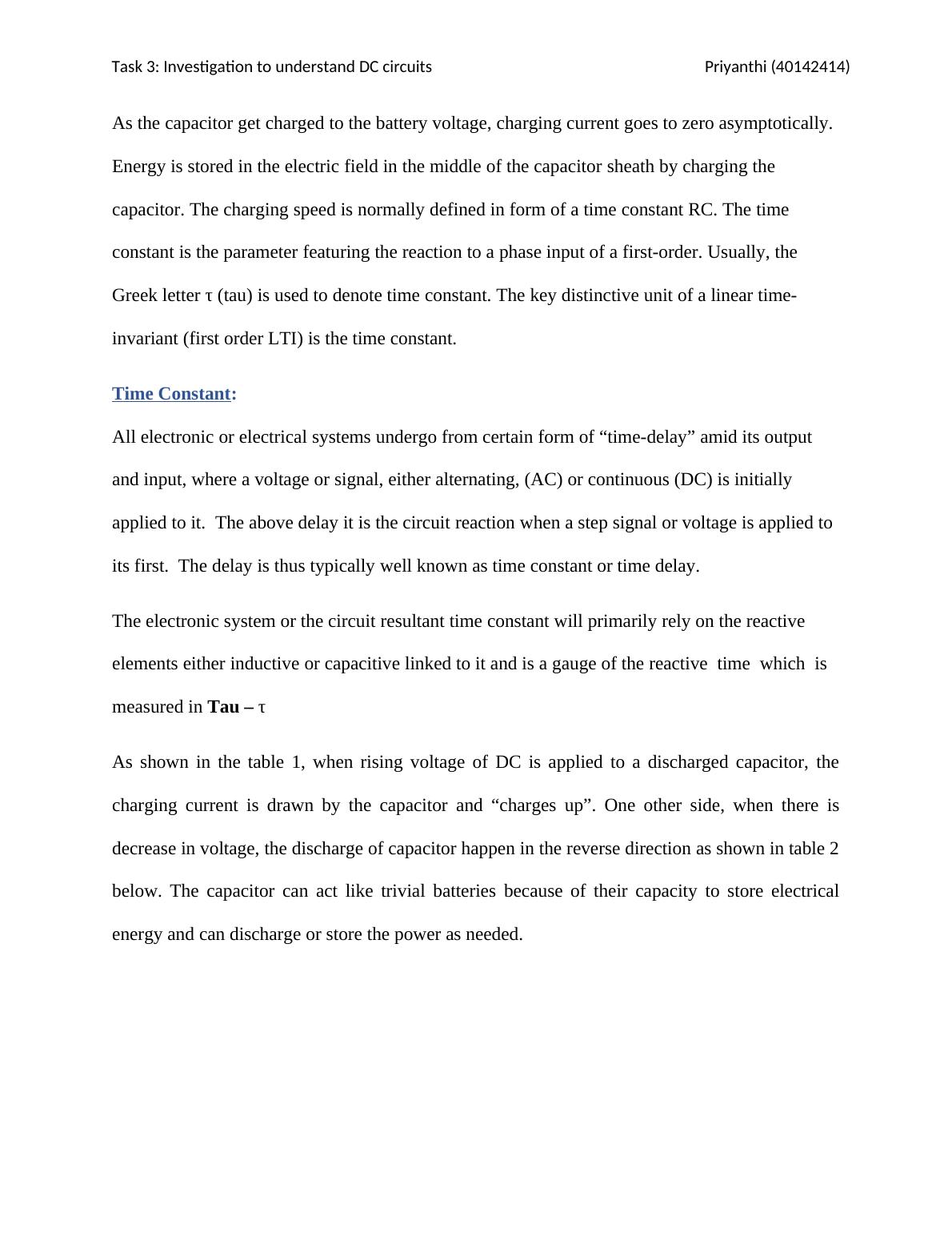
As the capacitor get charged to the battery voltage, charging current goes to zero asymptotically.
Energy is stored in the electric field in the middle of the capacitor sheath by charging the
capacitor. The charging speed is normally defined in form of a time constant RC. The time
constant is the parameter featuring the reaction to a phase input of a first-order. Usually, the
Greek letter τ (tau) is used to denote time constant. The key distinctive unit of a linear time-
invariant (first order LTI) is the time constant.
Time Constant:
All electronic or electrical systems undergo from certain form of “time-delay” amid its output
and input, where a voltage or signal, either alternating, (AC) or continuous (DC) is initially
applied to it. The above delay it is the circuit reaction when a step signal or voltage is applied to
its first. The delay is thus typically well known as time constant or time delay.
The electronic system or the circuit resultant time constant will primarily rely on the reactive
elements either inductive or capacitive linked to it and is a gauge of the reactive time which is
measured in Tau – τ
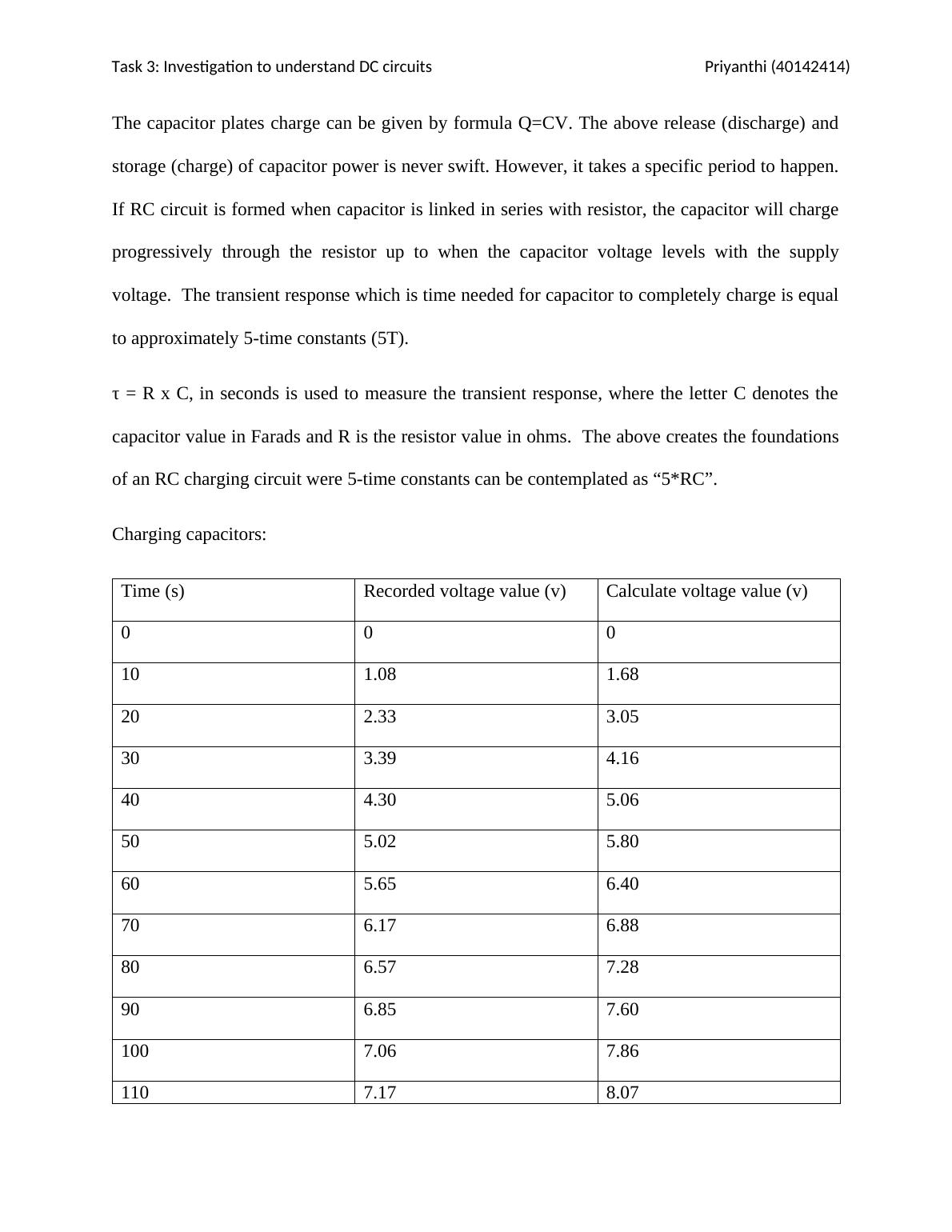
As shown in the table 1, when rising voltage of DC is applied to a discharged capacitor, the
charging current is drawn by the capacitor and “charges up”. One other side, when there is
decrease in voltage, the discharge of capacitor happen in the reverse direction as shown in table 2
below. The capacitor can act like trivial batteries because of their capacity to store electrical
energy and can discharge or store the power as needed.
Investigation to understand DC circuits_1
Task 3: Investigation to understand DC
circuits
Priyanthi
(40142414)
The capacitor plates charge can be given by formula Q=CV. The above release (discharge) and
storage (charge) of capacitor power is never swift. However, it takes a specific period to happen.
If RC circuit is formed when capacitor is linked in series with resistor, the capacitor will charge
progressively through the resistor up to when the capacitor voltage levels with the supply
voltage. The transient response which is time needed for capacitor to completely charge is equal
to approximately 5-time constants (5T).
τ = R x C, in seconds is used to measure the transient response, where the letter C denotes the
capacitor value in Farads and R is the resistor value in ohms. The above creates the foundations
of an RC charging circuit were 5-time constants can be contemplated as “5*RC”.
Charging capacitors:
Time (s) Recorded voltage value (v) Calculate voltage value (v)
0 0 0
10 1.08 1.68
20 2.33 3.05
30 3.39 4.16
40 4.30 5.06
50 5.02 5.80
60 5.65 6.40
70 6.17 6.88
80 6.57 7.28
90 6.85 7.60
100 7.06 7.86
110 7.17 8.07
Investigation to understand DC circuits_2
Task 3: Investigation to understand DC
circuits
Priyanthi
(40142414)
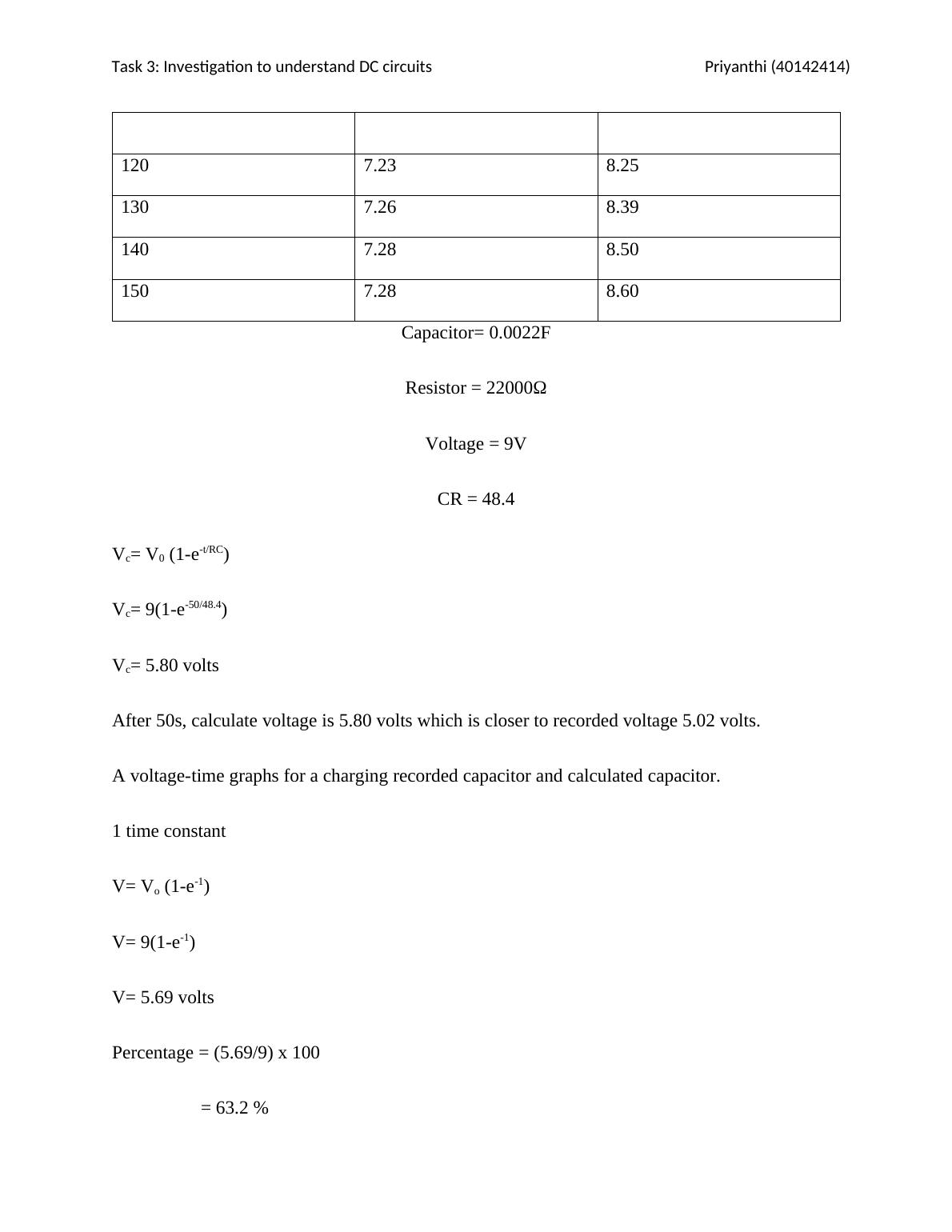
120 7.23 8.25
130 7.26 8.39
140 7.28 8.50
150 7.28 8.60
Capacitor= 0.0022F
Resistor = 22000Ω
Voltage = 9V
CR = 48.4
Vc= V0 (1-e-t/RC)
Vc= 9(1-e-50/48.4)
Vc= 5.80 volts
After 50s, calculate voltage is 5.80 volts which is closer to recorded voltage 5.02 volts.
A voltage-time graphs for a charging recorded capacitor and calculated capacitor.
1 time constant
V= Vo (1-e-1)
V= 9(1-e-1)
V= 5.69 volts
Percentage = (5.69/9) x 100
Investigation to understand DC circuits_3

End of preview

Want to access all the pages? Upload your documents or become a member.

Related Documents
Investigation of RC Circuit : Assignment
|12
|2136
|141

Electrical Assignment
|20
|2280
|248

Electronic Measurement and Testing Assignment
|13
|2092
|89

Electrical And Electronics Engineering Fundamentals
|20
|1774
|40

Power Supply Circuit
|4
|525
|20

DC Current
|5
|620
|128