Microwave Radio System: Calculating RSL & Passive Repeater Purpose
VerifiedAdded on 2023/03/31
|9
|1496
|251
Homework Assignment
AI Summary
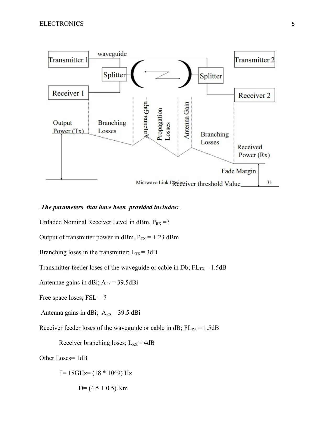
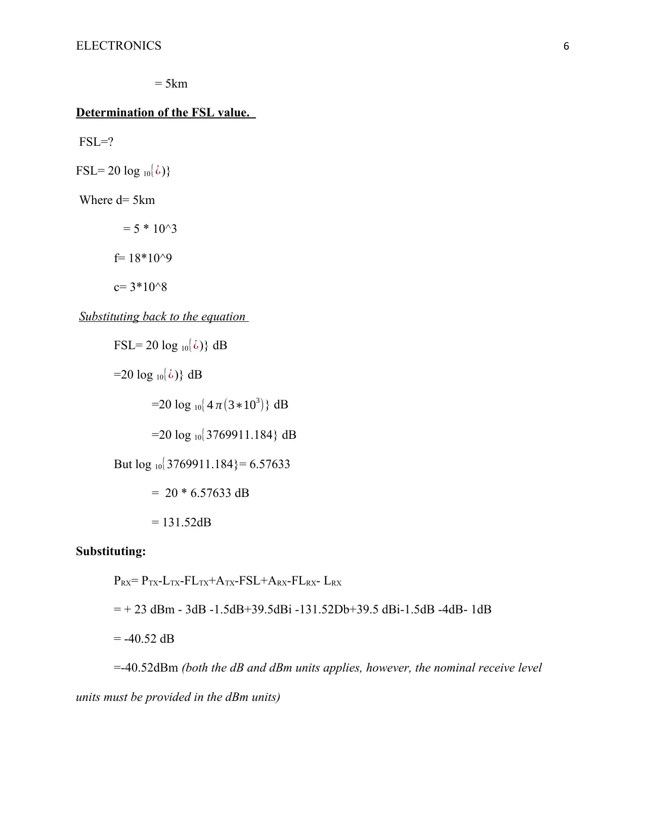
This assignment focuses on analyzing a digital microwave radio system operating in the 18GHz band with a 2x2 Mbps transmission capacity, utilizing a passive repeater between two sites. The solution involves calculating the nominal Receive Signal Level (RSL) at the receiver input in dBm under free space conditions, considering parameters such as transmitter RF output power, branching losses, antenna gains, and free space loss. The calculation yields an RSL of -40.52 dBm. Additionally, the assignment briefly discusses the purpose of passive repeaters in the system, highlighting their role in redirecting signals obstructed by obstacles, their minimal maintenance requirements, and their advantages over active repeaters in certain scenarios. The analysis employs a radio path link budget diagram to illustrate the system's components and signal flow.


1 out of 9
Related Documents


Your All-in-One AI-Powered Toolkit for Academic Success.
+13062052269
info@desklib.com
Available 24*7 on WhatsApp / Email
![[object Object]](/_next/static/media/star-bottom.7253800d.svg)
Copyright © 2020–2026 A2Z Services. All Rights Reserved. Developed and managed by ZUCOL.