logo

Microwave Link Calculation

Calculate the nominal Receive Signal Level (RSL) and discuss the purpose of the passive repeater in a digital microwave radio system. Also, research and present findings on advanced wireless technologies.

7 Pages734 Words93 Views
   

Added on  2023-03-31

About This Document

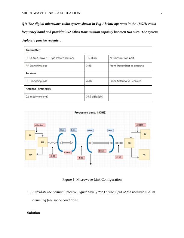
This document provides a calculation for the nominal Receive Signal Level (RSL) at the input of the receiver in dBm for a digital microwave radio system operating in the 18GHz radio frequency band. It also explains the purpose of passive repeaters in microwave transmission.

Microwave Link Calculation

Calculate the nominal Receive Signal Level (RSL) and discuss the purpose of the passive repeater in a digital microwave radio system. Also, research and present findings on advanced wireless technologies.

   Added on 2023-03-31

ShareRelated Documents
Running head: MICROWAVE LINK CALCULATION 1
Microwave link calculation
Name of Student
Institution Affiliation
Microwave Link Calculation_1
MICROWAVE LINK CALCULATION 2
Q1: The digital microwave radio system shown in Fig 1 below operates in the 18GHz radio
frequency band and provides 2x2 Mbps transmission capacity between two sites. The system
deploys a passive repeater.
Figure 1: Microwave Link Configuration
1. Calculate the nominal Receive Signal Level (RSL) at the input of the receiver in dBm
assuming free space conditions
Solution
Microwave Link Calculation_2
MICROWAVE LINK CALCULATION 3
Solving this problem will first necessitate us to be able to master some of the basic
concepts, which will be of significance in analyzing the radio link microwave transmission
system. We will thus be required to understand the term link budget, which refers to the results
of the gains and losses in a microwave radio communication link. These losses and gains are
available in the antennas, transmission lines, transmitters, and the environment in which the
signal is being transmitted. Also, the process of transmission is also affected by free space loses,
which are directly proportional to the length of the communication link. This implies that a more
extended link will be characterized by higher loses while a short link will register a few loses
(Jiang et al., 2016).
Since the transmitter is operating under unfading conditions, we will use the below
formula in the determination of the nominal receiver level.
PRX= PTX-LTX-FLTX+ATX-FSL+ARX-FLRX- LRX
Where PRX= Unfaded Nominal Receiver Level in dBm
PTX = output of transmitter power in dBm
LTX =branching loses in the transmitter
FLTX = transmitter feeder loses of the waveguide or cable in dB
ATX = the antennae gains in dBi (McDonald, 2015)
FSL = the free space loses
ARX = the antenna gains in dBi,
FLRX =receiver feeder loses of the waveguide or cable in dB
LRX =receiver branching loses
Microwave Link Calculation_3

End of preview

Want to access all the pages? Upload your documents or become a member.

Related Documents
DIGITAL MICROWAVE RADIO SYSTEM.
|6
|412
|489

Networking Concepts
|6
|516
|351

Purpose of passive repeaters in the microwave transmission Questions 2022
|5
|415
|2

Understanding Link Budget in Radio Link Microwave Transmission System
|8
|1093
|197

Link Budget Analysis in Electronics
|9
|1496
|251