Energy Scenario in Pakistan: Current Energy Shortage and Roots of Energy Crisis
VerifiedAdded on 2023/06/09
|127
|16149
|421
AI Summary
This article discusses the energy scenario in Pakistan, including the current energy shortage and the roots of energy crisis. It covers the government's policies, energy sources, consumption, and production. The article also highlights the historical and emerging energy crises in the world.
Contribute Materials
Your contribution can guide someone’s learning journey. Share your
documents today.

1CHEMICAL ENGINEERING
Chemical Engineering
[Name of the student]
[Name of the University]
[Author note]
Chemical Engineering
[Name of the student]
[Name of the University]
[Author note]
Secure Best Marks with AI Grader
Need help grading? Try our AI Grader for instant feedback on your assignments.
2CHEMICAL ENGINEERING
Chapter 1:
Energy Scenario in Pakistan:
Influence upon the social prosperity along with in the planning for long term usage of the
energy resources which are domestic in nature in order have stability in the economy of the
developing countries which includes Pakistan which is dependent upon the energy sectors
growth. Since last few years it has been seen that Pakistan is facing an energy crisis which is
totally unprecedented. The demand for energy has exceeded beyond the indigenous supplies
which has initially lead to the situation where Pakistan has become dependent upon imported oil
which acts as a substantial burden upon the country’s economy.
Government of Pakistan has been associated with perusing of certain policies so as to
confirm the security of the energy supply of the country and also to increase the domestic
supplies, diversifying of the imports and attracting of more foreign investments in order to
include the coal, natural gas and electricity which initially encourages the economic inter-fuel
substitution along with the promotion of the energy efficiency and renewable energy. This was
also done in order to provide support to the regional as well as to the interregional cooperation.
Pakistan is generally considered to be the ideal location where foreign private investment can be
made in order to upstream and downstream the hydrocarbon sector. This is mainly done for the
purpose of providing a deregulated transparent level playing field for all.
An increase in the primary commercial energy supplies was witnessed in the financial
year of 2009-10 which was around 0.8 %( i.e. 62.6 million tons of oil to 63.1 million tons of oil
from the year 2008-2009 to 2009-2010). The increased rate of supply came from various sources
which included the hydel electricity (0.1 mtoe), nuclear electricity (0.3 mtoe), natural gas (0.6
mtoe), and imported electricity (0.01 mtoe). As compared to the last year there was a decrease in
the supplies of the LPG, oil and coal. The different shares that the various sources of energy
3CHEMICAL ENGINEERING
were having in the year of 2009-2010 are 48.8% of natural gas, which was followed by the
31.4% oil, 10.6% of hydro-electricity, 7.3% of coal, 1.1% of nuclear energy, o.6% of LPG and
lastly 0.1% of electricity.
There was an increase in the natural gas production from 4002 to 4063 million cubic feet
per day in the year of 2009-2010, whereas the production of oil decreased to 64,948 barrels per
day to 65,845 barrels per day. A slow progress was seen in the drilling activity in the two
preceding years. In the year of 2009-10 about 26 explanatory wells were drilled whereas in the
year of 2008-2009 and 2007-2208 it was around 27. In the year of 2009-2010 about 42
development wells were drilled which was around 59 in the year of 2008-2009 and 53 in the year
of 2007-2008. The efforts made due to drilling resulted in 15 new discoveries which mainly
consisted of the gas/condensate and out of this 15 discoveries 7 were done by the OFDCL and 8
of them were discovered by the private sector companies.
There was an increase in the consumption of oil by 7% in the year of 2009-2010.the main
reason lying behind this was the increase in the consumption of motor spirit by 27% in the
transport sector and besides this the consumption of furnace oil increased by 16% in the power
sector. Besides this the consumption of E-10 fuel also increased which was added in the transport
sector this year. There was a decline in the consumption of fuels by 7% in domestic sector, 17%
in the agriculture sector and 12% in the government sector. There was a drop in the consumption
of furnace oil in the cement industry as well which was around 41% that is 105,4242 tons in the
year of 2008-2009 to 61,787 tons in the year of 2009-2010.
There was an increase in the importing of petroleum by 12% and it was also seen that the
importing of crude oil decreased by 15% than the previous years. The increase in the POL
occurred due to the increased rate of import of the furnace oil by 10%, motor sprit by 132% and
aviation fuel by 140%. The overall production of the refineries decreased by 8% and this resulted
4CHEMICAL ENGINEERING
in the less production of the kerosene by 21%, diesel furnace by 29%, and oil by 19% and
naphtha by 11%.
In the year of 2009-2010 the consumption of natural gas increased slightly by 1% than
the previous years and this increase in the consumption was due to the fertilizer by 22%,
transport by 12%, and industry by 5%, commercial by 4% and lastly domestic by 3%. There was
also decrease in the consumption of natural gas which was around 73% in the cement industries,
7% in the Pakistan steel mills and lastly 9% in the power sector.
There was also decrease in the production of coal as well by 7% in the year of 2009-2010
and this mainly happened due to the lower rate of production by the Baluchistan and the KPK
coalfields. The importing of coal had increased slightly by 0.13% and this initially resulted in the
3% decrease on the overall coal supplies/consumption. There was also increase in the
consumption of coal for generating power and the increase was about 12% that is from 112520
tons to 125482 tons.
Commissioning of five new IPPs were done in the power sector and this includes the
Engro, Orient, Atlas, Saif Power and lastly Nishat in the year of 2009-10. This initially resulted
in the providing of help for increasing the installed capacity that the power plant was having
which was seen to be around 1089MW in the year of the 2009-10.
In the year of 2009-10 the generation of electricity also increased by 4.1% which reached
an amount of about 95608 GWh. The generation of electricity mainly included thermal energy of
about 67.3%, hydel energy of about 29.4%, nuclear energy of about 3.0% and the imported
amount of electricity was around 0.3%. The consumption of electricity increased by 5.7% which
was around 74348 GWh and was more than the amount of the last year which was around 70371
GWh last year. The major amount of increased rate of consumption was seen in the domestic
sector which was around 1990 GWh, agriculture which was around 894 GWh, industry sector
Secure Best Marks with AI Grader
Need help grading? Try our AI Grader for instant feedback on your assignments.
5CHEMICAL ENGINEERING
which was around 494 GWh, commercial sector which was around 354 GWh and lastly in the
bulk supplies which was around 241GWh. There also occurred a reduction in the losses of T&D
public sector power system and the reduction was from 21.6% to 20.6% in the year of 2009-10.
1.2. Roots of Energy Crisis
1.2.1. Historical crises
Oil crisis in the year of 1973: the major cause lying behind the crisis was that exporting
of one of the OPEC oil was restricted and this was done by the major Arab oil-producing
states and this happened when support was being provided by the western Israel at the
time of Yom Kippur War.
Energy crisis of 1979: the major cause lying behind this was the Iranian revolution
Rise in oil price in the year of 1990: Gulf war was the major cause behind this.
Electricity crisis of California in the year of 2000-200: the major cause included the
failure in deregulation as well as in the business corruption.
Fuel protest of UK in the year of 2000: the major cause lying behind this was the increase
in crude oil’s price which were added with the existing high taxation on the road fuel in
the UK.
Natural gas crisis of North America.
2004 energy crises of Argentina
From many years there existed energy shortage in North Korea
Shortage in energy supplies was also experienced by Zimbabwe for many years which
mainly occurred due to mismanagement of finance.
1.2.2. Emerging shortage
Within 40 years it is estimated that the second largest oil field Kuwait’s Al Burqan Oil Filed
would get depleted.
6CHEMICAL ENGINEERING
The major crises which are existing in today’s world mainly includes the following:
Increase in the price of fuel since 2003 and this was mainly caused due to the increased global
demand of petroleum which initially coupled with the production stagnation, along with the fall
in US dollars value along with other several causes.
The central Asian crisis of 2008 which was mainly caused due to the abnormal temperature and
the level of water in the areas which are dependent upon the hydroelectric power. Although there
existed significant number of hydrocarbon reserves in February 2008 but still the President of
Pakistan was associated with announcement of plans in order to tackle the shortages which were
was moving towards the stage of crisis. Along with this the president of South African President
was also associated with appeasing the fears related to the prolonged crisis of electricity in the
country of South Africa.
Electrical crisis of South Africa was estimated to be lasting till 2012 which was responsible for
the rise in price of platinum in February 2008 which also resulted in the reduction of gold
production.
Towards the end of 2005 China also experienced severe amount of shortage in energy which
occurred again in the early days of 2008. At the time of latter crisis China also suffered severe
amount of damage in the power networks associated with the shortage in the amount of diesel
and coal. The supplies of electricity in the Guangdong province was estimated to have a short
fall of 10 GW.
1.3. Current Energy Shortage in Pakistan:
July 2008
Power crisis is also suffered by Pakistan which is the world’s sixth most populous
country and by power it means electric power not political power. In the year of 2001 it was seen
7CHEMICAL ENGINEERING
that the country had an excess power capacity of 4000 megawatts. In today’s world it has been
seen that there exists 15% shortfall in the capacity that is needed. The main reason lying behind
the shortfall is mainly due in the parts due to the existence of dry weather that is responsible for
the reduction in the output of hydropower. Another major lying behind this is due to the poor
quality of planning. Pakistan also had the high capacity of hydropower and large deposits of coal
however it has been seen to be very slow for the purpose of exploiting the resources.
Besides this it has also been seen that Pakistan is associated moving more and more
towards the energy crisis and it has been seen that shortfall in this has been associated with
hitting a record of level of around 7,075 MW in the month of July which initially resulted in
gradual shutdown of around 24 units of the plants generating power which was followed by
severe scarcity of fuel. According to a source there was a situation which initially pushed to
customers to bear the brunt of 18 to 20 hours load shedding and this might seem to be increasing
due to various factors
The WAPDA has been associated with facing an electricity shortfall of 5750 MW within
its own system and along with this in the IPPs there was a recorded shortfall of about 1325 MW.
The IPPs are associated with including the country’s largest IPP which was having the capacity
of around 1600 MW Kot Addu Power Company (KAPCO), 120MW Japan, 365 MW AES Pak-
Gen. limited and fifty percent shutdown of 117 MW Southern Electric Power Company (Sepcol),
362 MW AES Lalpir, 586 Uch Power Limited. Kot Addu Power Company (KAPCO), country’s
largest IPP with a capacity of 1600 MW, which compromised of 10 multi fuel fired gas.
The present situation on ground can be stated that there is a lack in the capacity addition
which would be associated with causing a shortage in the power to an extent of 5,500 MW in the
year of 2010. Besides this the current shortfall taking place in the demand of electricity and the
supply mainly occurred due to the inability of the government to make the entire payments and
this initially forced towards the closure of some of the thermal power plants.
Paraphrase This Document
Need a fresh take? Get an instant paraphrase of this document with our AI Paraphraser
8CHEMICAL ENGINEERING
According to the official records it was seen that the generation from the Pepco,s own
thermal power plant had shrunk to the low ebb because of the fact that Pepco was not capable of
purchasing the fuel oil from its suppliers. Wapda’s thermal plant was capable of producing a
maximum amount of 1900 MW electricity on 20th August against their capacity of about of 4829
MW and this mainly happened due to the inability of purchasing the furnace oil along with the
minor technical faults in gears, clutches and the switches.
Similarly the generation occurring from the IPPs was seen to be around 3470 MW on 19th
August which occurred against the capacity of 6115 MW which again occurred because of the
fiscal constraints. The same thing has been occurring since last two months as the total thermal
power generation remained less and this was seen to be around 6000 MW which is against the
total capacity that is around 12000 MW.
Due to all this thing Pakistan State Oil which is the largest and state owned supplier had
refused the making of payments to all the refineries or lift fuel oil. Due to all this reason the
refining the capacity of some of the refineries had reduced by an amount of one-third and
because of this the shortage constraints lead to the shortage in the consumer market of the
petroleum product.
Besides the availability of the generating capacity of around 18000MW Pepco plants were not
having the capability of generating more than an amount of 12000 MW for the last two months
in spite of having the maximum amount of power generation due to the hydropower projects
which mainly due to the high rate of flow of water in the rivers because of the monsoon season.
Karachi Situation
The system of Karachi Electric Supply Company’s is consisting of the thermal plants in
Karachi which were not capable of generating more than 1,300MW electricity against their
capacity of about 1,800MW. The major reason lying behind this was due to the technical
problems that lead to shortage in the fuel.
9CHEMICAL ENGINEERING
The companies producing Oil and gas were associated with making demands regarding
the enforcement of laws which would be responsible for providing power to the suppliers to stop
the supply to the power companies in case when they are not capable or fails to make payments
in time. Along with this few lenders also realized the fact that if it is not done then, the
continuous debt of the energy sector would be associated with making various oils and gas
companies face turmoil’s in their financial conditions and would also be responsible for keeping
the foreign investors away from few of the firms.
1.4 Reason for Less Electricity Production
1. It has cost much more than 400 billion INR for the circular death in the inter-corporate region
and it has been becoming much larger in the energy sector for the looming of widespread default.
This is due to the fact that many companies have now started to default the commitments in
technical terms and financial terms.
2. It has been reported by the oil firms that they have been unable to ensure the smooth supply of
generating independent power procedure or IPPS in the further Days Ahead and they are running
at last for generating the capacity due to the financial crunch that they feel while they have been
purchasing fuel.
3. The government is taking the authority to eliminate the. It has been reported that the electricity
rates and Sceneries of 16 per cent in the last month and with the withdrawal of the “general sales
tax” along with the implementation of additional 61 per cent increase would take place after the
Presidential elections.
5. It is also been reported that the gas rates that is the natural gas rates has seen a considerable
rise twice by the month and this mainly happened due to the fact that the democratic government
had taken over and have been associated with increasing the oil prices much more than 50 per
10CHEMICAL ENGINEERING
cent. There has been escalation in all sorts of essential and non-essential commodities and this is
given a rise in the cost of utility.
6. Digging deep into the problem it could be seen that there have been on payment of areas by
public sector companies and government entities that have resulted in the problem. They have
been more than 130 billion INR of receivables by the Pakistan electric power company or Pepco
and the allied powers it has. On the other hand the Karachi electric power supply company or
Kesc has an overdue bill of 56 billion INR to Pepco while there are other areas that is governed
by the federally administered tribal areas which have an overdue bill of almost 75 billion INR as
a counted on 31st July.
7. There is an overdue bill of another 18 Million INR to the Electricity Distribution Company by
the Federal government provinces in JK and also there are some public sector corporations that
or this amount to the company all together.
The organization of Pepco and chest have put together the total accumulated table of about 100
billion INR. Out of this total amount Pepco has to pay 64 billion INR to IPPS which would limit
their ability of buying the oil and continue the run on less than half of the total capacity.
However, the Pepco organization has also to pay the outstanding of about 10 billion INR and 1
billion INR to Oil and Gas companies respectively.
In accordance to that it is the inability of the government that they have not been able to clear the
outstanding bill of 84 billion INR to the all companies and refineries with only one claim of price
differential. The PDC amount is expected to be of March high range but the burden for that has
been clearly replaced with the borrowing of even more expensive amount in accordance from the
commercial banks. It has been reported that the government has paid off near about 50 Billion
INR sofa to the oil companies and Refineries with the help of arranging of syndicated loans from
Secure Best Marks with AI Grader
Need help grading? Try our AI Grader for instant feedback on your assignments.
11CHEMICAL ENGINEERING
the market and it is also been reported that PSO has over 25 billions INR of receivables both
from IPPS and pepco.
Therefore the government has not been able to perform a differential claim on liquid petroleum
and it is also been reported that the marketing forms of oil and refinery is have informed that
they have been unable to make payments to the oil refinery to the government.
This has been the Re occurrence of the energy sector that that has been into corporate
which is used in the early 1990s. This is a situation that has been much worse in today's time
according to what a senior official in the ministry of finance has been dealing with. The person
has been appointed this issue as a chronic one. This is such a situation that energy sector crisis
can become much was in the short run because of the destruction and the kind of problems that
has been created in the oil supplier risk and there has been reports of much higher scale of load
shedding that kept on having occurrences for another year. Further in the long run that has been
deficiency of budget which is supposedly expected to go much beyond 8per cent of GDP by the
end of the current year. The currency of Pakistan has already slammed and hit Rock bottom
whereas the development schemes are still being curtailed and even the cost of safeguarding the
sovereign bonds from the default has been increasingly rising so far as to reach almost ripple the
amount since October last year and the Foreign Exchange Reserves have reported to be declined
by a total of 7 billion INR which is only enough to cover 3 months of the imports.
This is a much interesting term that the current state of the power load shedding that has been or
curing rapidly has emerged primarily as there have been financial crisis and shortage of well and
this is not due to the capacity constraints as they have been portrayed as per the government. The
government has sofa activated the load shedding as a fault of the previous Government and
therefore they have been trying to enhance the generation capacity because there has been an
increase demand of power consumption.
12CHEMICAL ENGINEERING
1.5. Gasification:
Gasification is generally considered to be a technological process which is associated with the
conversion of carbonaceous (carbon based) raw material by making use of the heat, steam &
pressure into synthesis gas. The process is associated with involving the reaction of
carbonaceous feedstock with an oxygen containing reagent that might include an oxygen, air,
steam or carbon dioxide. This is generally done at a temperatures which is more than 800°C. The
process is also associated with taking into account the partial oxidation of substance. This means
only a partial amount of oxygen is supplied in a limited way so as to make sure that the entire
fuel is not completely oxidized. This ultimately results in the partial combustion. Despite of
being largely exothermic, there still exists the requirement of some heat in order to initiate the
process of gasification and also for the purpose of sustaining it in order to have operation which
are effective. Besides this the demand of Gasification systems is also increasing, which is mainly
happening due to the fact that they are being used in order to turn the feed stocks such as the
transformation of the coal into useful chemical products like ammonia.
Synthesis gas is considered to be the main product, which mainly includes the following:
1. Methane
2. Carbon monoxide
3. Hydrogen
Basically the gases which are produced due to gasification would be consisting of a net calorific
value which is around 4 – 10 MJ/Nm3. Some of the major products which are produced due to
gasification mainly includes a solid residue of non-combustible materials (ash) that mainly
contains carbon which is relatively low in amount.
13CHEMICAL ENGINEERING
1.6. History of Gasification:
1850-1940 Production of ―town gas‖ for light & heat.
Gasification of coal- All gas for fuel & light
1940-1975 Production of synthetic fuel
Production of liquid fuel & chemicals
1975-1990 First Integrated Gasification Combined
Cycle (IGCC) electric power plant
1990-2000 financial support was provided by the US
Agencies to help the IGCC process
2000-present Turnkey thermal & power Greenhouse gas
from biomass
1.7. Chemistry of Gasification:
When the gasification of the solid carbon is done whether it is in the form of coal, coke, char or
biomass, some major chemical reactions takes place which mainly involves the generation of:
a. Carbon dioxide
b. Water (Steam)
c. Methane
d. Carbon
e. Hydrogen
Paraphrase This Document
Need a fresh take? Get an instant paraphrase of this document with our AI Paraphraser
14CHEMICAL ENGINEERING
f. Carbon monoxide
The reactions are provided below:
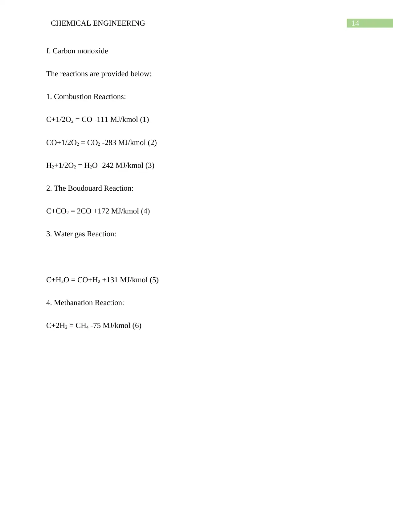
1. Combustion Reactions:
C+1/2O2 = CO -111 MJ/kmol (1)
CO+1/2O2 = CO2 -283 MJ/kmol (2)
H2+1/2O2 = H2O -242 MJ/kmol (3)
2. The Boudouard Reaction:
C+CO2 = 2CO +172 MJ/kmol (4)
3. Water gas Reaction:
C+H2O = CO+H2 +131 MJ/kmol (5)
4. Methanation Reaction:
C+2H2 = CH4 -75 MJ/kmol (6)
15CHEMICAL ENGINEERING
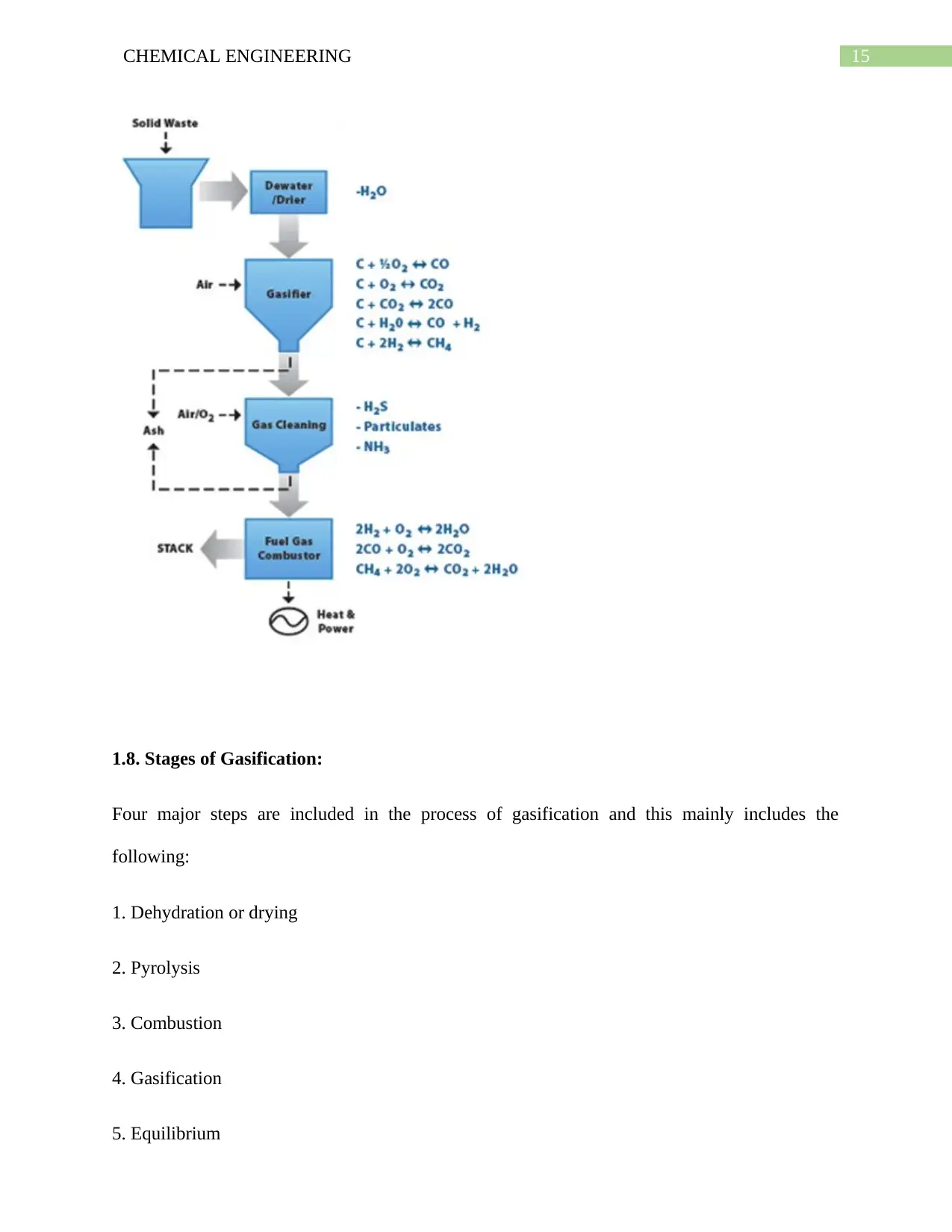
1.8. Stages of Gasification:
Four major steps are included in the process of gasification and this mainly includes the
following:
1. Dehydration or drying
2. Pyrolysis
3. Combustion
4. Gasification
5. Equilibrium
1.8. Stages of Gasification:
Four major steps are included in the process of gasification and this mainly includes the
following:
1. Dehydration or drying
2. Pyrolysis
3. Combustion
4. Gasification
5. Equilibrium
16CHEMICAL ENGINEERING
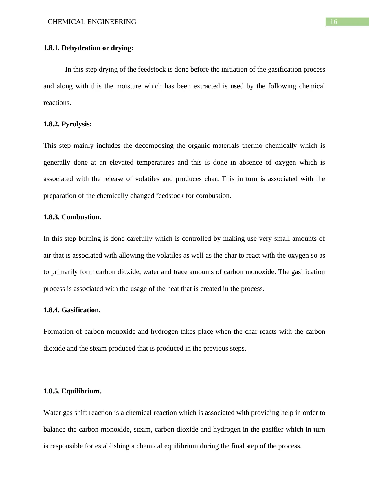
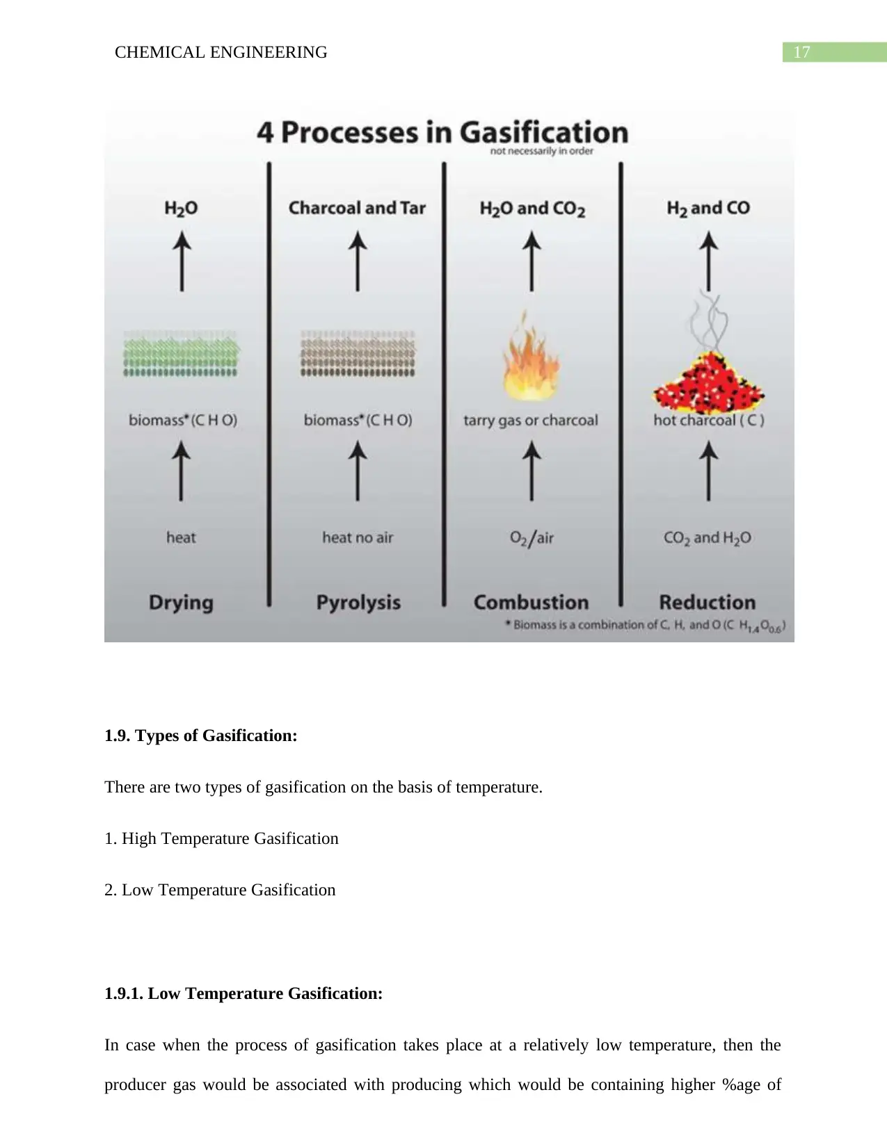
1.8.1. Dehydration or drying:
In this step drying of the feedstock is done before the initiation of the gasification process
and along with this the moisture which has been extracted is used by the following chemical
reactions.
1.8.2. Pyrolysis:
This step mainly includes the decomposing the organic materials thermo chemically which is
generally done at an elevated temperatures and this is done in absence of oxygen which is
associated with the release of volatiles and produces char. This in turn is associated with the
preparation of the chemically changed feedstock for combustion.
1.8.3. Combustion.
In this step burning is done carefully which is controlled by making use very small amounts of
air that is associated with allowing the volatiles as well as the char to react with the oxygen so as
to primarily form carbon dioxide, water and trace amounts of carbon monoxide. The gasification
process is associated with the usage of the heat that is created in the process.
1.8.4. Gasification.
Formation of carbon monoxide and hydrogen takes place when the char reacts with the carbon
dioxide and the steam produced that is produced in the previous steps.
1.8.5. Equilibrium.
Water gas shift reaction is a chemical reaction which is associated with providing help in order to
balance the carbon monoxide, steam, carbon dioxide and hydrogen in the gasifier which in turn
is responsible for establishing a chemical equilibrium during the final step of the process.
Secure Best Marks with AI Grader
Need help grading? Try our AI Grader for instant feedback on your assignments.
17CHEMICAL ENGINEERING
1.9. Types of Gasification:
There are two types of gasification on the basis of temperature.
1. High Temperature Gasification
2. Low Temperature Gasification
1.9.1. Low Temperature Gasification:
In case when the process of gasification takes place at a relatively low temperature, then the
producer gas would be associated with producing which would be containing higher %age of
18CHEMICAL ENGINEERING
hydrocarbons that is much greater as compared with the temperature of gasification. Due to this
reason it might be used directly in order to burn so as to obtain heat or electricity generation by
making use of the steam turbine so as to initiate one of the internal combustion engine which
would be then resulting in the production of electricity.
1.9.2. High Temperature Gasification:
In this process of gasification a temperature range of 1200-1600oC is involved that is assocated
with the production of few hydrocarbons in the product gas, along with higher proportion of CO
& H2. Synthesis Gas is the gas which is produced during this process, and this is mainly due to
the reason that this is used for the purpose of synthesizing the longer chain hydrocarbons by
making use of techniques such as Fischer-Tropsch (FT) synthesis.
1.10. Gasifier:
A chemical reactor that converts feedstock (wood, biomass, coal) into a combustible gas that can
be used for:
a. Cooking
b. Heating, or
c. Running an internal combustion engine.
Partial combustion of feedstock in the reactor is used for the achieving this. Along with this the
heat generated to pyrolyze or thermally breaks down the rest of the material into volatile gases is
also used.
Feedstock + Limited Oxygen = CO2 + H2O + C + Associated Volatile Hydrocarbons + Heat
So it can be stated that the gasifier is associated with converting most of the feedstock into the
flammable gases by having some ash as well as unburned charcoal residue.
19CHEMICAL ENGINEERING
1.11. Types of Gasifier:
Due to the occurrence of the air and oxygen interaction with the feedstock present inside the
gasifier, they would be classified according to the way by which the oxygen or air gets
introduced in it. There exists three types of gasifier and this mainly includes the following:
1. Updraft Gasifier or Counter-current Gasifier
2. Downdraft Gasifier or Co-current Gasifier
3. Cross draft Gasifier
1.11.1. Updraft or Counter-Current Gasifier
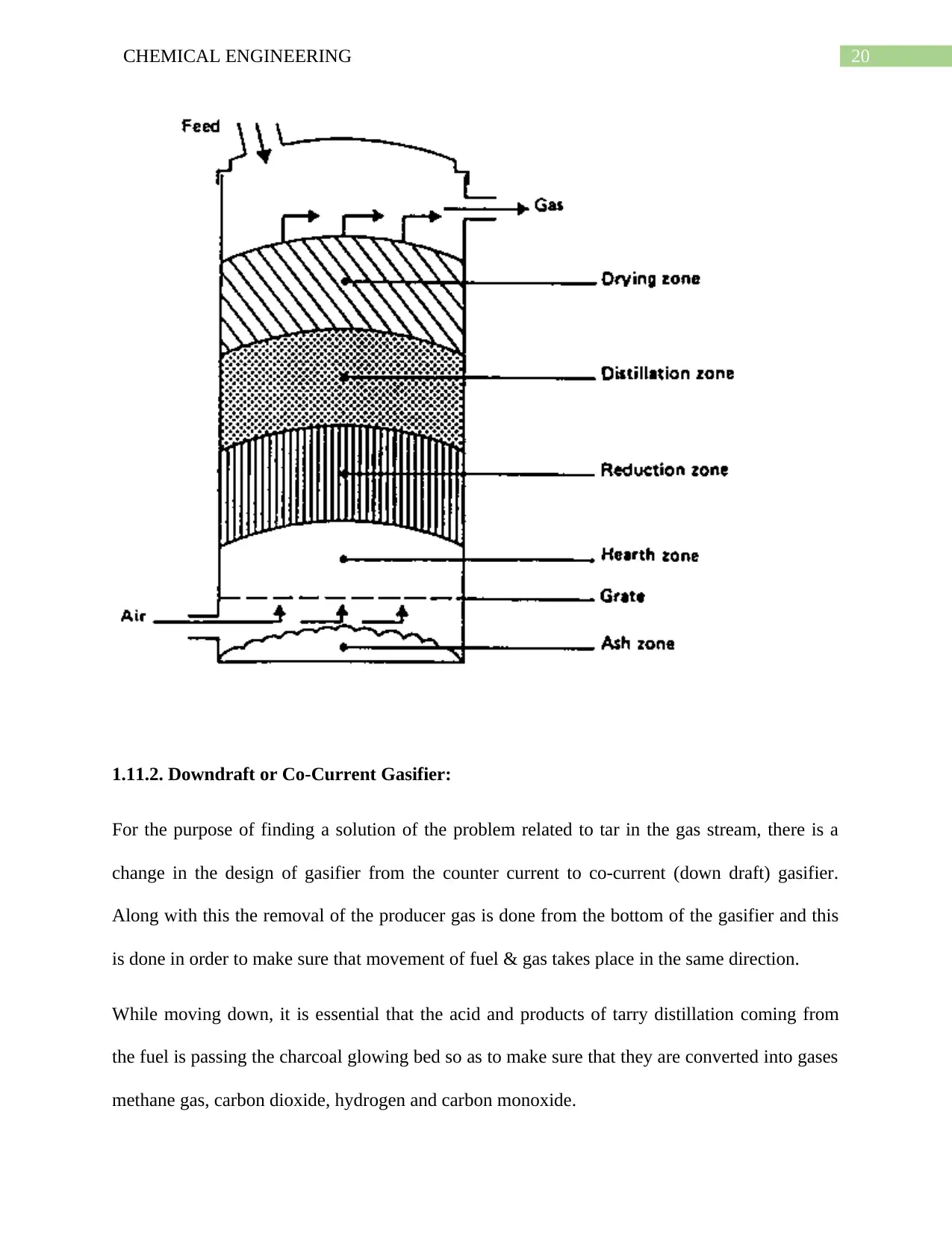
In this gasifier the gas is introduced in the bottom of the gasifier and from the bottom the air
gradually moves upwards & leaves from the top of the gasifier. It is seen that the combustion
reaction occurs near the grate which is present in the bottom. After this the reduction reactions
occurs. Whereas in the upper section of the gasifier, it is seen that the feedstock is associated
with undergoing the heating and the pyrolysis which happens due to transfer of heat due to
forceful convection as well as due to the radiation from the lower zones.
Paraphrase This Document
Need a fresh take? Get an instant paraphrase of this document with our AI Paraphraser
20CHEMICAL ENGINEERING
1.11.2. Downdraft or Co-Current Gasifier:
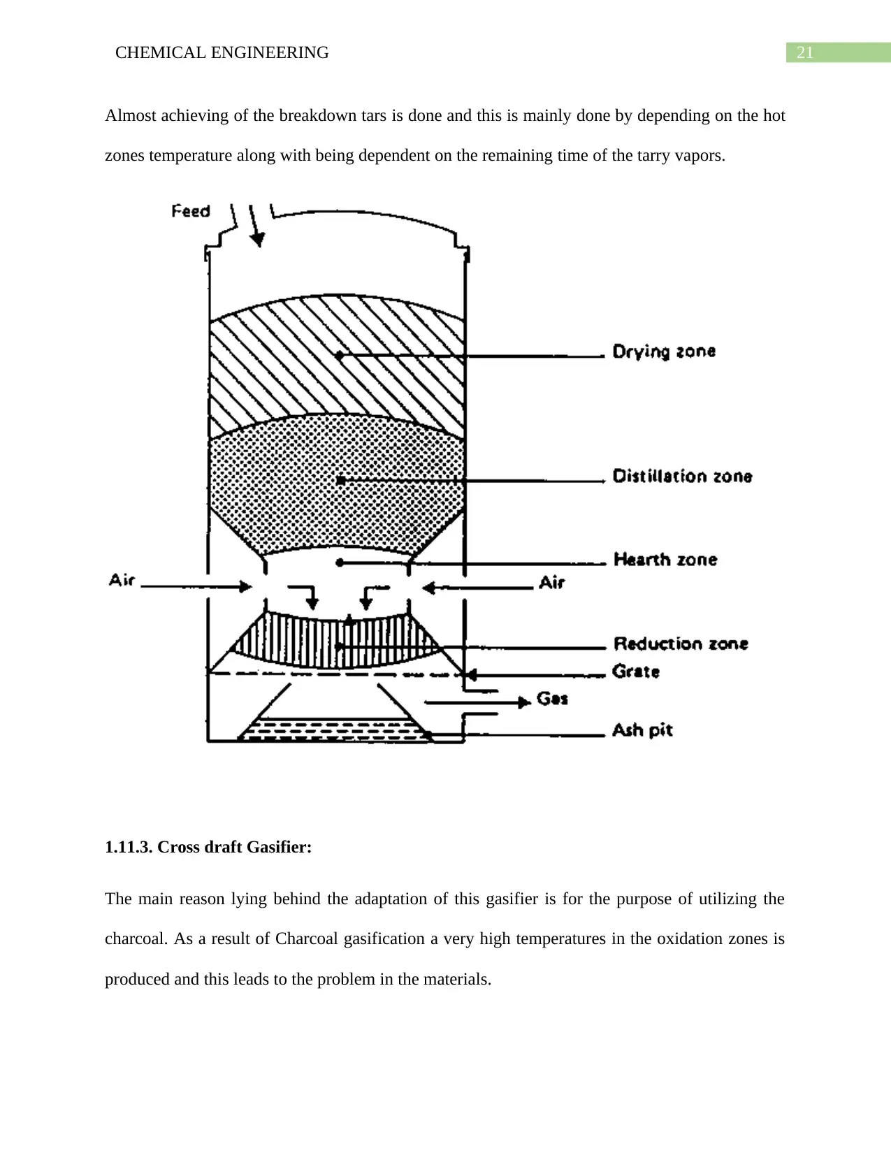
For the purpose of finding a solution of the problem related to tar in the gas stream, there is a
change in the design of gasifier from the counter current to co-current (down draft) gasifier.
Along with this the removal of the producer gas is done from the bottom of the gasifier and this
is done in order to make sure that movement of fuel & gas takes place in the same direction.
While moving down, it is essential that the acid and products of tarry distillation coming from
the fuel is passing the charcoal glowing bed so as to make sure that they are converted into gases
methane gas, carbon dioxide, hydrogen and carbon monoxide.
21CHEMICAL ENGINEERING
Almost achieving of the breakdown tars is done and this is mainly done by depending on the hot
zones temperature along with being dependent on the remaining time of the tarry vapors.
1.11.3. Cross draft Gasifier:
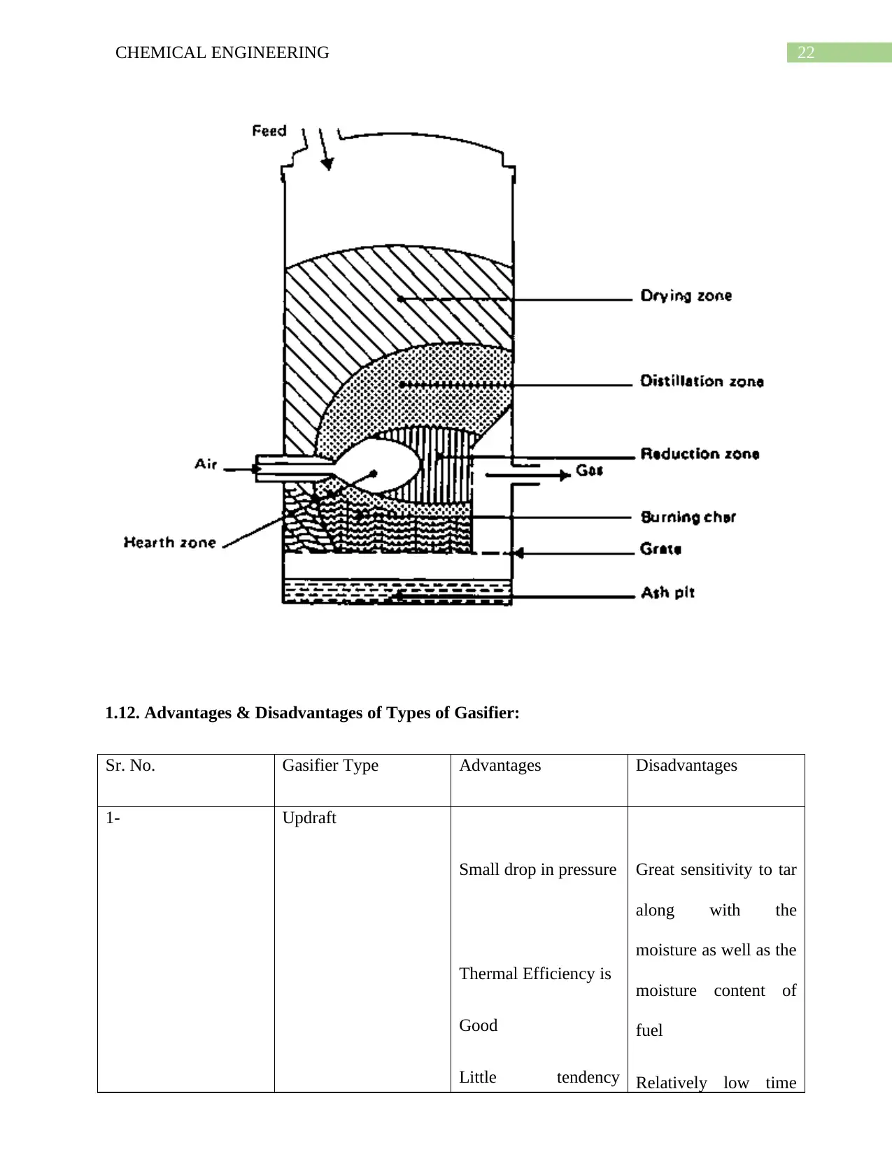
The main reason lying behind the adaptation of this gasifier is for the purpose of utilizing the
charcoal. As a result of Charcoal gasification a very high temperatures in the oxidation zones is
produced and this leads to the problem in the materials.
22CHEMICAL ENGINEERING
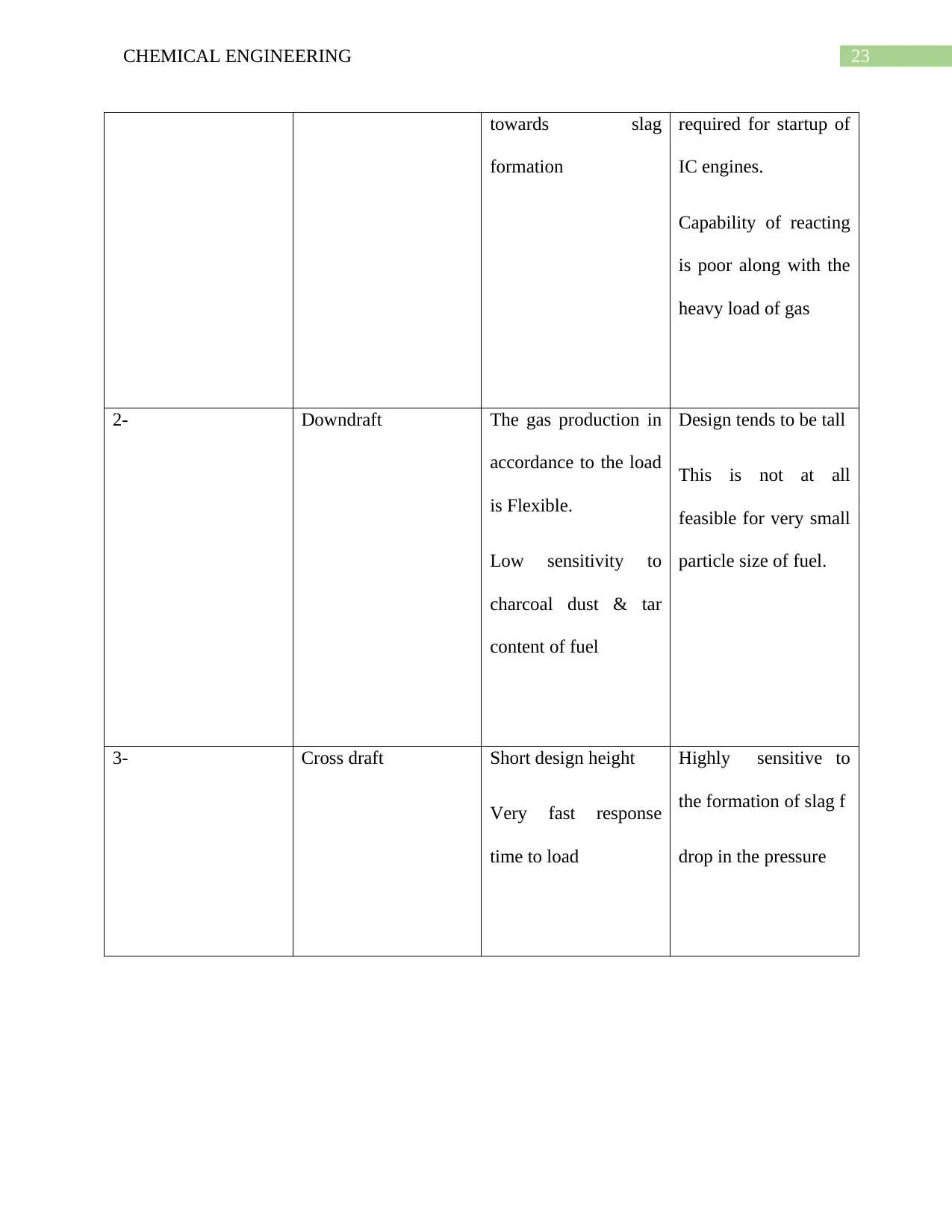
1.12. Advantages & Disadvantages of Types of Gasifier:
Sr. No. Gasifier Type Advantages Disadvantages
1- Updraft
Small drop in pressure
Thermal Efficiency is
Good
Little tendency
Great sensitivity to tar
along with the
moisture as well as the
moisture content of
fuel
Relatively low time
1.12. Advantages & Disadvantages of Types of Gasifier:
Sr. No. Gasifier Type Advantages Disadvantages
1- Updraft
Small drop in pressure
Thermal Efficiency is
Good
Little tendency
Great sensitivity to tar
along with the
moisture as well as the
moisture content of
fuel
Relatively low time
Secure Best Marks with AI Grader
Need help grading? Try our AI Grader for instant feedback on your assignments.
23CHEMICAL ENGINEERING
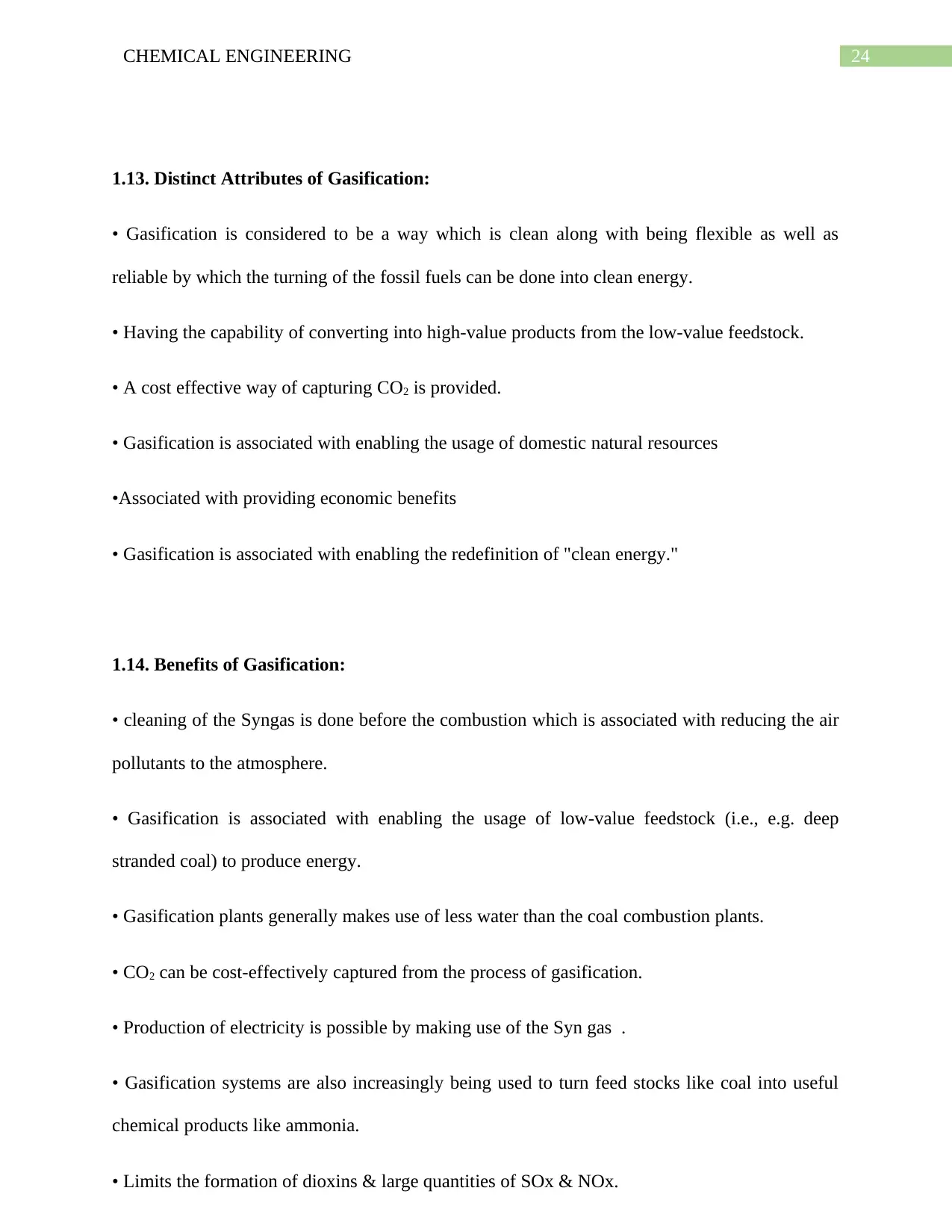
towards slag
formation
required for startup of
IC engines.
Capability of reacting
is poor along with the
heavy load of gas
2- Downdraft The gas production in
accordance to the load
is Flexible.
Low sensitivity to
charcoal dust & tar
content of fuel
Design tends to be tall
This is not at all
feasible for very small
particle size of fuel.
3- Cross draft Short design height
Very fast response
time to load
Highly sensitive to
the formation of slag f
drop in the pressure
24CHEMICAL ENGINEERING
1.13. Distinct Attributes of Gasification:
• Gasification is considered to be a way which is clean along with being flexible as well as
reliable by which the turning of the fossil fuels can be done into clean energy.
• Having the capability of converting into high-value products from the low-value feedstock.
• A cost effective way of capturing CO2 is provided.
• Gasification is associated with enabling the usage of domestic natural resources
•Associated with providing economic benefits
• Gasification is associated with enabling the redefinition of "clean energy."
1.14. Benefits of Gasification:
• cleaning of the Syngas is done before the combustion which is associated with reducing the air
pollutants to the atmosphere.
• Gasification is associated with enabling the usage of low-value feedstock (i.e., e.g. deep
stranded coal) to produce energy.
• Gasification plants generally makes use of less water than the coal combustion plants.
• CO2 can be cost-effectively captured from the process of gasification.
• Production of electricity is possible by making use of the Syn gas .
• Gasification systems are also increasingly being used to turn feed stocks like coal into useful
chemical products like ammonia.
• Limits the formation of dioxins & large quantities of SOx & NOx.
25CHEMICAL ENGINEERING
• Gasification is capable of competing effectively in the high-cost energy environments
• Gasification is associated with converting the abundant low-value feed stocks into high-value
products.
1.13. Environmental Benefits of Gasification:
Some of the major environmental benefits have been listed below:
1. Reduced air emissions:
Achievement of a significant reductions in the air emission by making use of gasification
associated with the capturing of CO2, which is done at cost which is reduced as compared to
other alternatives of post-combustion capture.
2. Water usage:
Swan Hills Synfuels ISCG is associated with the usage of water which are not fresh in the
gasification process and this mainly includes the saline water.
3. Ability to sequester carbon dioxide (CO2):
Capturing of the CO2 can be done cost-effectively and sequestered by making use of the
commercial technologies in a gasification system before it is released into the atmosphere.
4. Ability to Use Coal Gasification for Clean Power Generation:
Combining of the cycle power generation can be fueled up with the Low- carbon content ISCG
syngas which initially lead to air emissions levels that is low than the emission by the l coal-fired
power or by the natural gas-fired combined cycle generation.
1.16. Disadvantages of Gasification:
The process of gasification is having a lot of benefits but still there exists certain disadvantages
which mainly includes the following:
Paraphrase This Document
Need a fresh take? Get an instant paraphrase of this document with our AI Paraphraser
26CHEMICAL ENGINEERING
• releasing of Tars, heavy metals, halogens and alkaline compounds along with the gas released
as output product which are capable of creating problems for the environment and operations.
• Agglomeration is increased by the alkalis in the fluidized beds which is utilized by few of the
gasification systems
• Heavy metals are toxic in nature which are also having the capability of getting accumulates
whenever gets in contact with the outside environment.
• Halogens are corrosive in nature which are responsible for the occurrence of acid rain
1.17. Comparison of Gasification to other Technologies:
1.17.1. Gasification v/s Combustion/ Incineration
Sr. No. Gasification Combustion/ Incineration
1- Converts solid fuel into a
gaseous fuel by making
use of a process which is
also termed as high
temperature oxidation-
reduction reaction.
Converts solid fuel into
gaseous products of
combustion through high
temperature oxidation
reactions.
2- Gasification packages are
heated up so as to form
chemical bonds which is
generally done by the
conversion of the energy.
Combustion is associated
with releasing the energy
to form high temperature
product gas.
3- Designed for the purpose
of having maximized
Designed for the purpose
of having maximized
27CHEMICAL ENGINEERING
conversion of waste to
CO & H2.
conversion of waste to
CO2 & H2O.
4- Operates under controlled
amount of oxygen.
Employs large quantities
of excess air.
1.18. Biomass:
Solar energy has various products one of which is the biomass so it is considered to be a
renewable source of carbon & hydrogen that basically consists of energy as well as chemical
products.
Biomass can be defined by making use of the following attempts:
1) The entire life that an animal and plant is having.
2) Biomass is considered to be one of the organic product which means that it harnesses the solar
energy and is considered to be a photochemical approach which can be converted into different
forms of energy.
3) Biomass can be considered to be an organic matter which is obtained from the plants as well
as due to the photosynthesis.
6CO2 + 6H2O + Sunlight + Chlorophyll = C6H12O6 + 6O2 + Chlorophyll
1.19. Advantages of Biomass Systems:
1. Renewable
conversion of waste to
CO & H2.
conversion of waste to
CO2 & H2O.
4- Operates under controlled
amount of oxygen.
Employs large quantities
of excess air.
1.18. Biomass:
Solar energy has various products one of which is the biomass so it is considered to be a
renewable source of carbon & hydrogen that basically consists of energy as well as chemical
products.
Biomass can be defined by making use of the following attempts:
1) The entire life that an animal and plant is having.
2) Biomass is considered to be one of the organic product which means that it harnesses the solar
energy and is considered to be a photochemical approach which can be converted into different
forms of energy.
3) Biomass can be considered to be an organic matter which is obtained from the plants as well
as due to the photosynthesis.
6CO2 + 6H2O + Sunlight + Chlorophyll = C6H12O6 + 6O2 + Chlorophyll
1.19. Advantages of Biomass Systems:
1. Renewable
28CHEMICAL ENGINEERING
2. Dependent on energy already available which is having the amount of minimum capital input.
3. capability of being developed by usage of the existing manpower & material sources.
4. Reasonably priced.
5. Biomass energy is unique because:
a. availability in the main geographical locations.
b storing of solar energy is done effectively
c. renewable source of energy obtained from carbon that is processed into solid, liquid & gaseous
fuel.
7. The vast majority of the rural population is dependent on biomass as fuel. Some sources of
biomass are as follows:
a. Wood & Woody Wastes
b. Crop Residues
c. Organic Wastes
d. Agricultural Wastes
7. Biomass is not responsible for global warming. Low level of sulfur & ash in biomass prevents
formation of acid rain. Biomass energy has numerous benefits which includes the following:
a. use of conventional fuels is reduced.
b. environmental pollution is reduced.
c. improvement in the economy of the Nation
8. The environmental benefits include reduction in air & water pollution reducing CO2 emission,
greenhouse gases like SO2.
Secure Best Marks with AI Grader
Need help grading? Try our AI Grader for instant feedback on your assignments.
29CHEMICAL ENGINEERING
9. Gestation period is Low.
10. Generation of Rural employment.
11. Production of less ash which minimizes cost of disposal.
12. Production of Electrical energy in large scale at low cost.
1.20. Applications of Biomass:
The applications of biomass are as follows:
1. Direct thermal application:
a. Boiler
b. Institutional cooking & other thermal applications.
2. product gas is used as fuel for the following:
a. IC engines, vehicles
b. Irrigation water pumping/ village water supply.
3. Bio fuel applications
a. Ethanol for transport applications
4. Generation of electricity
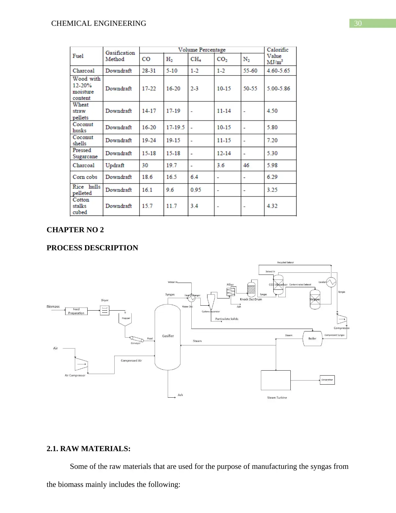
1.21. Composition of Producer Gas from various fuels:
The various kind of fuel whenever undergoes the gasification is associated with producing
different composition of producer gas has been provided below:
30CHEMICAL ENGINEERING
CHAPTER NO 2
PROCESS DESCRIPTION
2.1. RAW MATERIALS:
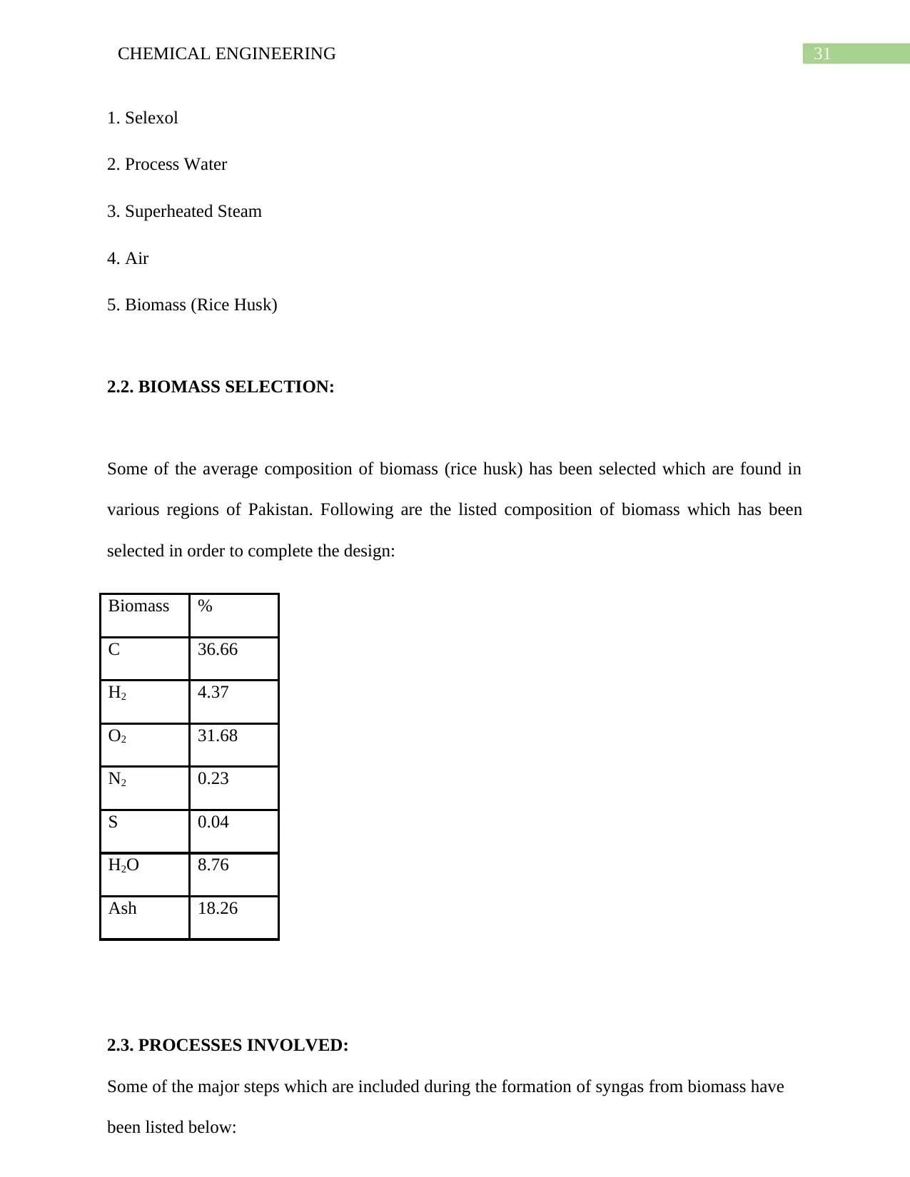
Some of the raw materials that are used for the purpose of manufacturing the syngas from
the biomass mainly includes the following:
CHAPTER NO 2
PROCESS DESCRIPTION
2.1. RAW MATERIALS:
Some of the raw materials that are used for the purpose of manufacturing the syngas from
the biomass mainly includes the following:
31CHEMICAL ENGINEERING
1. Selexol
2. Process Water
3. Superheated Steam
4. Air
5. Biomass (Rice Husk)
2.2. BIOMASS SELECTION:
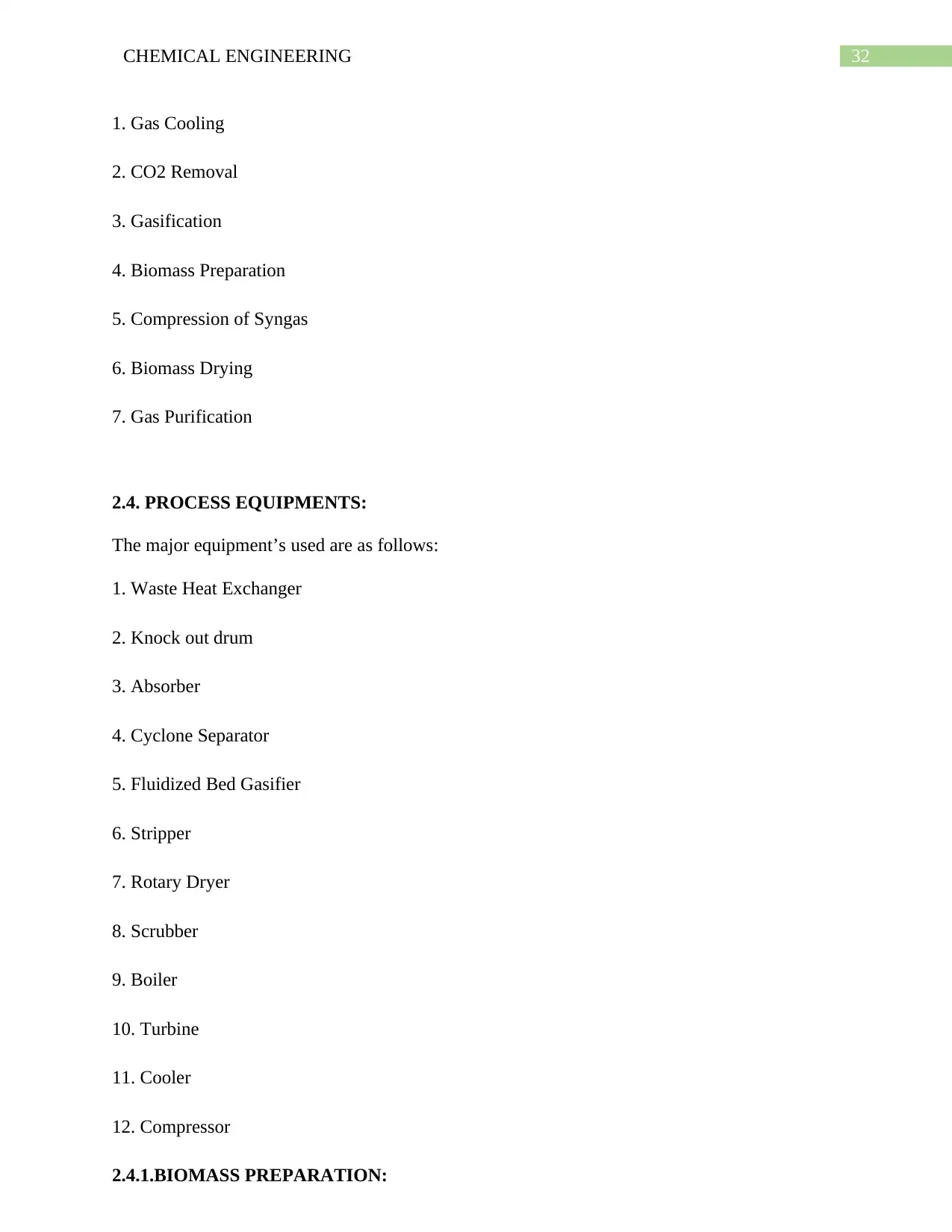
Some of the average composition of biomass (rice husk) has been selected which are found in
various regions of Pakistan. Following are the listed composition of biomass which has been
selected in order to complete the design:
Biomass %
C 36.66
H2 4.37
O2 31.68
N2 0.23
S 0.04
H2O 8.76
Ash 18.26
2.3. PROCESSES INVOLVED:
Some of the major steps which are included during the formation of syngas from biomass have
been listed below:
Paraphrase This Document
Need a fresh take? Get an instant paraphrase of this document with our AI Paraphraser
32CHEMICAL ENGINEERING
1. Gas Cooling
2. CO2 Removal
3. Gasification
4. Biomass Preparation
5. Compression of Syngas
6. Biomass Drying
7. Gas Purification
2.4. PROCESS EQUIPMENTS:
The major equipment’s used are as follows:
1. Waste Heat Exchanger
2. Knock out drum
3. Absorber
4. Cyclone Separator
5. Fluidized Bed Gasifier
6. Stripper
7. Rotary Dryer
8. Scrubber
9. Boiler
10. Turbine
11. Cooler
12. Compressor
2.4.1.BIOMASS PREPARATION:
33CHEMICAL ENGINEERING
Before rice husk can be delivered in the rotary dryer it
is crucial to bypass it through some education steps like for example, it is necessary to do away
with dirt particles and different pointless fabric related with chance husk for
this reason screening is accomplished through the usage
of particular sieves keeping in thinking the common particle size of rice husk is 1mm. In case of
rice husk, as particle measurement is already pretty small consequently in
addition size reduction is now not required.
Next step after education of biomass is drying of rice husk as it incorporates8.76per cent
moisture so it is essential to decrease the moisture contents in any other case it may
additionally reason issues in the gasifier especially in combustion manner and will make
it difficult to maintain the stoichiometric ratio of biomass to steam in gasifier and
will also enlarge the load on heat exchanger used after gasifier.
For this reason rotary dryer is used that reduces the moisture contents from 8.76per cent to
2.80per cent and the running efficiency of the rotary dryer is considered as 80per cent
Now the rice husk is prepared to be delivered in the gasifier. Gasifier used for this motive is
Fluidized Bed Gasifier due to the fact it offers well mixing of the biomass with oxidant. In our
case it makes simpler to control biomass and oxidant quantities to be introduced and as rice
husk consists of large amount of slag contents so it helps in to avoid the slagging of ash in the
gasifier.
2.4.2.BIOMASS DRYING:
Air is used as oxidant required for combustion procedure taking region in the gasifier. Before
sending it to the gasifier, it is first of all compressed in the Air Compressor which compresses it
to will increase its pressure. The running electricity of air compressor is 19.6 kW. After
compression it is then delivered into the gasifier.
34CHEMICAL ENGINEERING
Steam is required for the endothermic reactions taking location in the gasifier i.e. partial
combustion or gasification process. It is introduced at a temperature of 400 degree Celsius and at
a pressure of 62 bar by using the usage of a boiler that is run via fuel produced.
2.4.4.SELECTED GASIFIER:
Oxygen-Blown Fluidized Bed Gasifier is the selected type of gasifier it has advantages given
below:
1. Dry Ash (making it relatively simple to remove)
2. it is possible to change the air-to-fuel ratio in order to make sure that the bed temperature is
controllable..
3. Feedstock-fluidized beds are more tolerant.
4. Excellent gas–solid contact along with the large contact surface area.
5. Higher throughput than fixed bed gasifiers.
6. Smaller gas handling & cleanup equipment
7. Produces high heating value gas.
8. Reduced gasifier size
9. Low power requirement.
10. Reduced heat exchangers size
11. Improved heat and mass transfer
12. Reduced char
2.4.5. GAS COOLING:
Secure Best Marks with AI Grader
Need help grading? Try our AI Grader for instant feedback on your assignments.
35CHEMICAL ENGINEERING
Syn gas leaving the gasifier is at 800 degrees Celcius so it is necessary to remove excess heat
from it this is done by using a heat exchanger right after the gasifier that reduces its temperature
to 500 degrees Celcius and serves the purpose of preheating the boiler water as well. For this
purpose shell and tube type heat exchanger is used.
2.4.6. GAS PURIFICATION:
Syn gas produced contains large amount of ash contents, water vapors and some quantity of
unburnt rice husk so it is necessary to remove such material from syn gas before it can be used as
combustible gas.
2.4.7.SELEXOL SYSTEM DESCRIPTION:
The Selexol process makes use of bodily solvent to get rid of acid fuel from the streams of
syngas. It is ideally suitable for the selective elimination of H2S and other sulphur compounds,
or for the bulk elimination of CO2. The Selexol process also eliminates COS, mercaptans,
ammonia, HCN and steel carbonyls.
1. A very low vapor stress that limits its losses to the treated gas
2. Low viscosity to avoid massive pressure

36CHEMICAL ENGINEERING
CHAPTER NO 3
MATERIAL BALANCE
CHAPTER NO 3
MATERIAL BALANCE
37CHEMICAL ENGINEERING
3.1. Material Balance around Dryer:
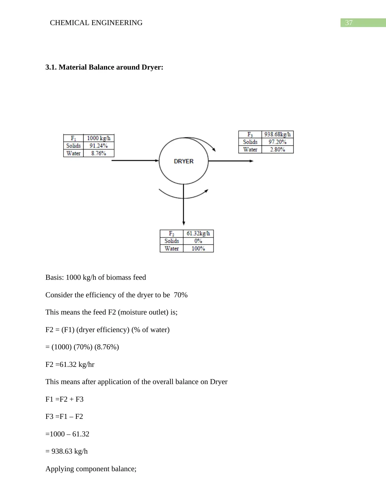
Basis: 1000 kg/h of biomass feed
Consider the efficiency of the dryer to be 70%
This means the feed F2 (moisture outlet) is;
F2 = (F1) (dryer efficiency) (% of water)
= (1000) (70%) (8.76%)
F2 =61.32 kg/hr
This means after application of the overall balance on Dryer
F1 =F2 + F3
F3 =F1 – F2
=1000 – 61.32
= 938.63 kg/h
Applying component balance;
Paraphrase This Document
Need a fresh take? Get an instant paraphrase of this document with our AI Paraphraser

38CHEMICAL ENGINEERING
Water balance:
(x1) (F1) = (x2) (F2) + (x3) (F3)
(0.0876)(1000) = (1) (61.32) + (x3) (938.6)
x3 = 0.028
Water balance:
(x1) (F1) = (x2) (F2) + (x3) (F3)
(0.0876)(1000) = (1) (61.32) + (x3) (938.6)
x3 = 0.028
39CHEMICAL ENGINEERING
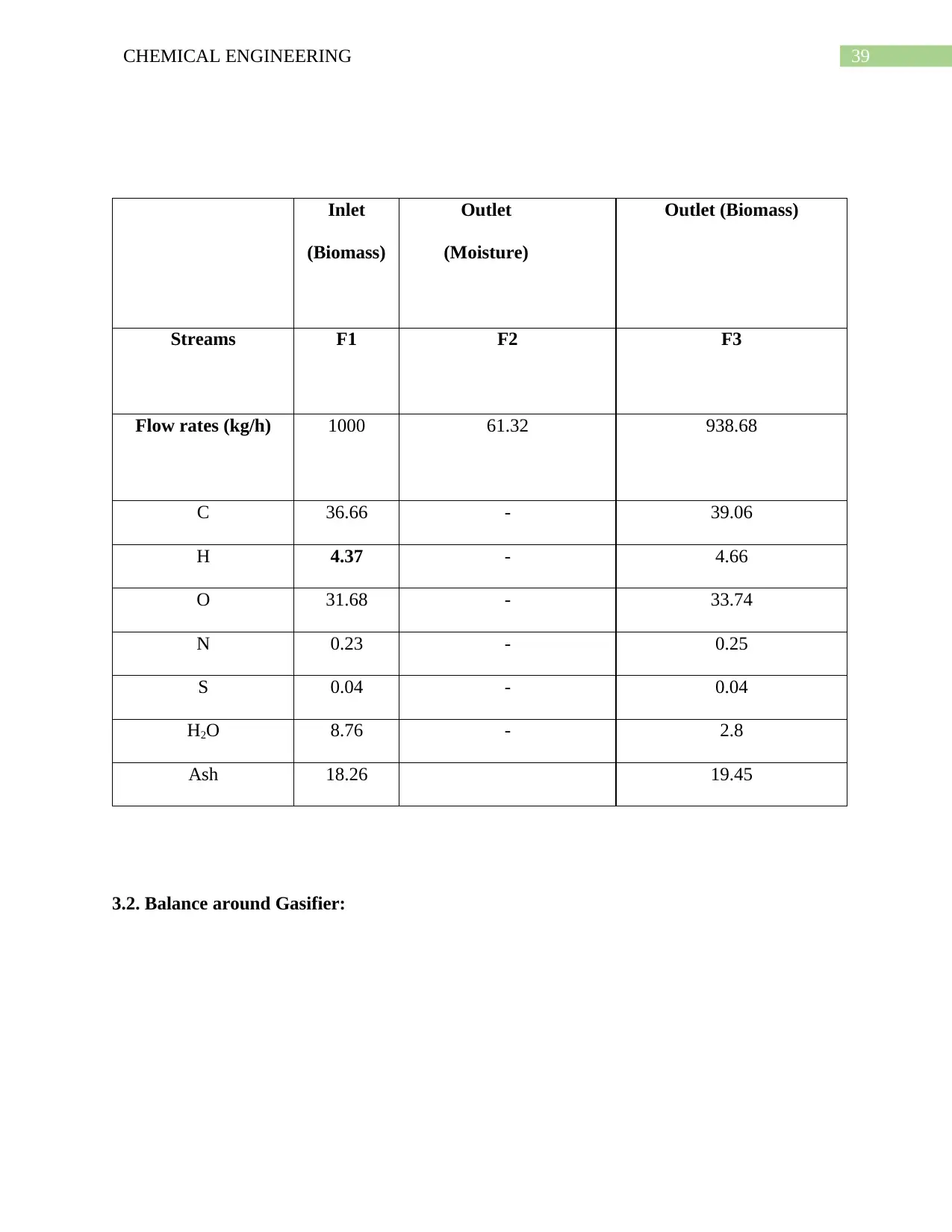
Inlet
(Biomass)
Outlet
(Moisture)
Outlet (Biomass)
Streams F1 F2 F3
Flow rates (kg/h) 1000 61.32 938.68
C 36.66 - 39.06
H 4.37 - 4.66
O 31.68 - 33.74
N 0.23 - 0.25
S 0.04 - 0.04
H2O 8.76 - 2.8
Ash 18.26 19.45
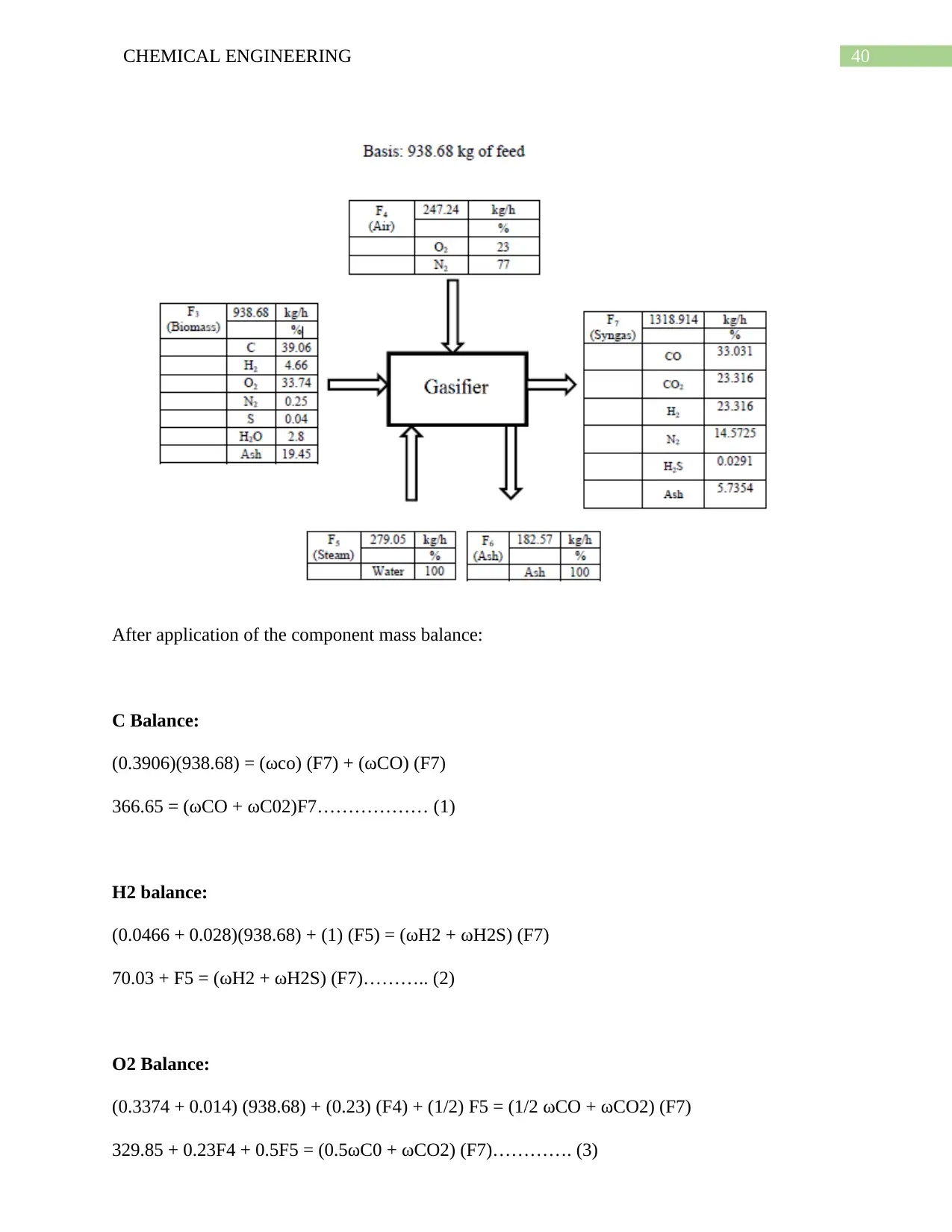
3.2. Balance around Gasifier:
Inlet
(Biomass)
Outlet
(Moisture)
Outlet (Biomass)
Streams F1 F2 F3
Flow rates (kg/h) 1000 61.32 938.68
C 36.66 - 39.06
H 4.37 - 4.66
O 31.68 - 33.74
N 0.23 - 0.25
S 0.04 - 0.04
H2O 8.76 - 2.8
Ash 18.26 19.45
3.2. Balance around Gasifier:
40CHEMICAL ENGINEERING
After application of the component mass balance:
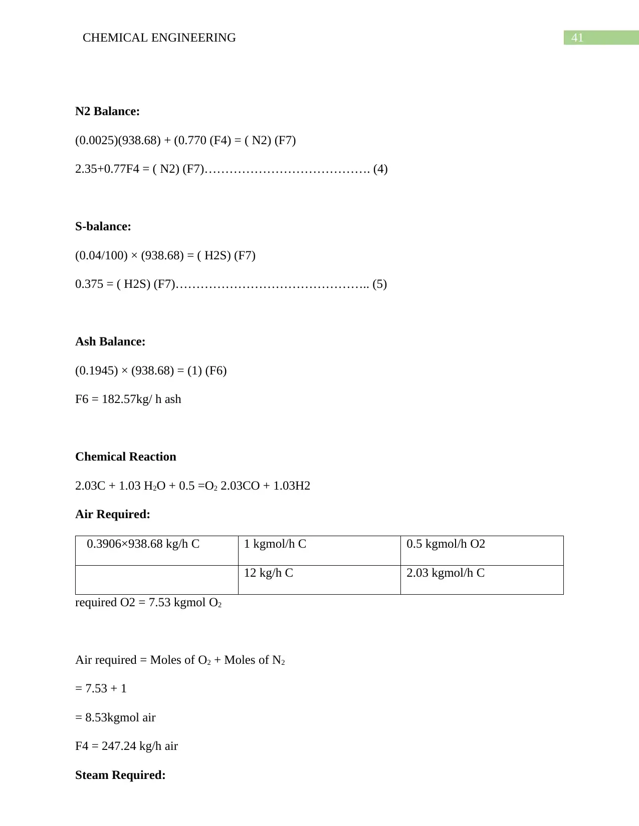
C Balance:
(0.3906)(938.68) = (ωco) (F7) + (ωCO) (F7)
366.65 = (ωCO + ωC02)F7……………… (1)
H2 balance:
(0.0466 + 0.028)(938.68) + (1) (F5) = (ωH2 + ωH2S) (F7)
70.03 + F5 = (ωH2 + ωH2S) (F7)……….. (2)
O2 Balance:
(0.3374 + 0.014) (938.68) + (0.23) (F4) + (1/2) F5 = (1/2 ωCO + ωCO2) (F7)
329.85 + 0.23F4 + 0.5F5 = (0.5ωC0 + ωCO2) (F7)…………. (3)
Secure Best Marks with AI Grader
Need help grading? Try our AI Grader for instant feedback on your assignments.
41CHEMICAL ENGINEERING
N2 Balance:
(0.0025)(938.68) + (0.770 (F4) = ( N2) (F7)
2.35+0.77F4 = ( N2) (F7)…………………………………. (4)
S-balance:
(0.04/100) × (938.68) = ( H2S) (F7)
0.375 = ( H2S) (F7)……………………………………….. (5)
Ash Balance:
(0.1945) × (938.68) = (1) (F6)
F6 = 182.57kg/ h ash
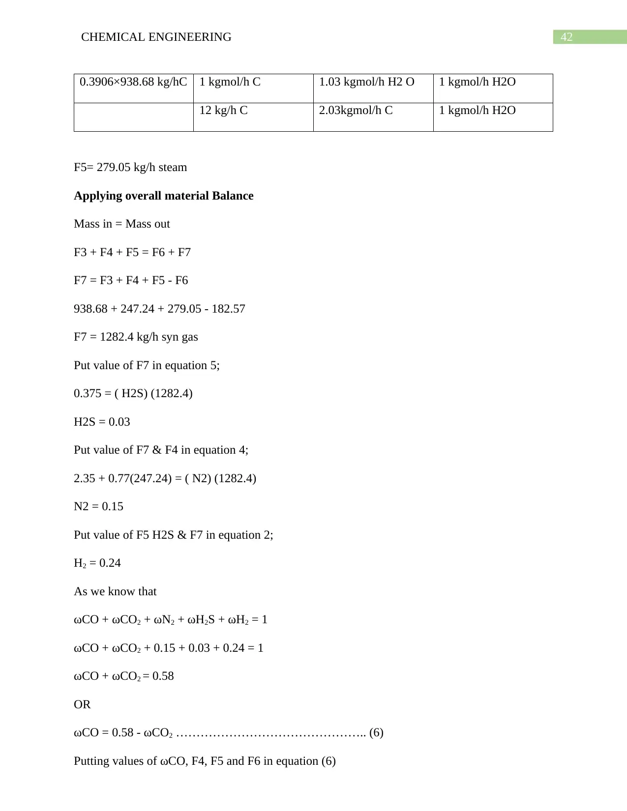
Chemical Reaction
2.03C + 1.03 H2O + 0.5 =O2 2.03CO + 1.03H2
Air Required:
0.3906×938.68 kg/h C 1 kgmol/h C 0.5 kgmol/h O2
12 kg/h C 2.03 kgmol/h C
required O2 = 7.53 kgmol O2
Air required = Moles of O2 + Moles of N2
= 7.53 + 1
= 8.53kgmol air
F4 = 247.24 kg/h air
Steam Required:
42CHEMICAL ENGINEERING
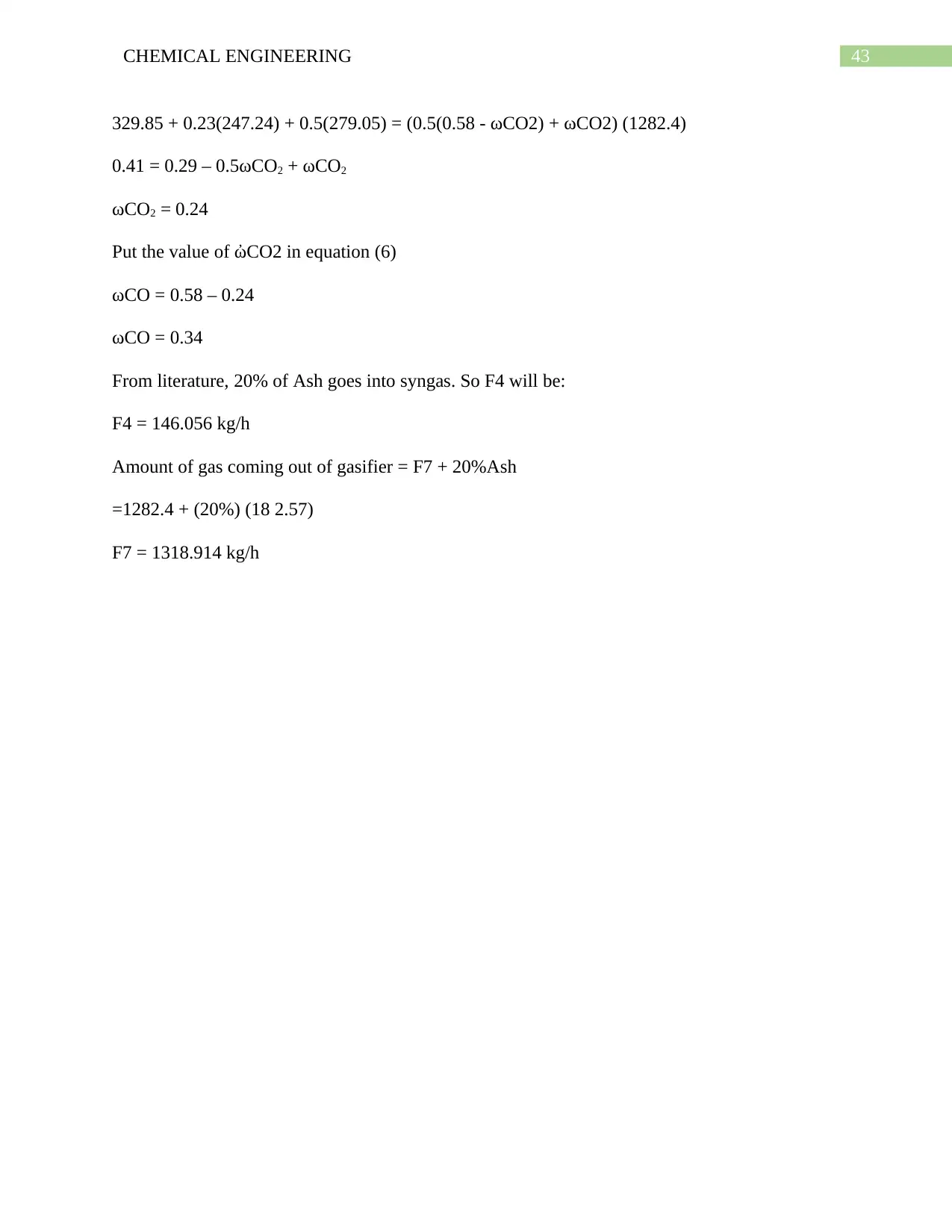
0.3906×938.68 kg/hC 1 kgmol/h C 1.03 kgmol/h H2 O 1 kgmol/h H2O
12 kg/h C 2.03kgmol/h C 1 kgmol/h H2O
F5= 279.05 kg/h steam
Applying overall material Balance
Mass in = Mass out
F3 + F4 + F5 = F6 + F7
F7 = F3 + F4 + F5 - F6
938.68 + 247.24 + 279.05 - 182.57
F7 = 1282.4 kg/h syn gas
Put value of F7 in equation 5;
0.375 = ( H2S) (1282.4)
H2S = 0.03
Put value of F7 & F4 in equation 4;
2.35 + 0.77(247.24) = ( N2) (1282.4)
N2 = 0.15
Put value of F5 H2S & F7 in equation 2;
H2 = 0.24
As we know that
ωCO + ωCO2 + ωN2 + ωH2S + ωH2 = 1
ωCO + ωCO2 + 0.15 + 0.03 + 0.24 = 1
ωCO + ωCO2 = 0.58
OR
ωCO = 0.58 - ωCO2 ……………………………………….. (6)
Putting values of ωCO, F4, F5 and F6 in equation (6)
43CHEMICAL ENGINEERING
329.85 + 0.23(247.24) + 0.5(279.05) = (0.5(0.58 - ωCO2) + ωCO2) (1282.4)
0.41 = 0.29 – 0.5ωCO2 + ωCO2
ωCO2 = 0.24
Put the value of ὠCO2 in equation (6)
ωCO = 0.58 – 0.24
ωCO = 0.34
From literature, 20% of Ash goes into syngas. So F4 will be:
F4 = 146.056 kg/h
Amount of gas coming out of gasifier = F7 + 20%Ash
=1282.4 + (20%) (18 2.57)
F7 = 1318.914 kg/h
Paraphrase This Document
Need a fresh take? Get an instant paraphrase of this document with our AI Paraphraser
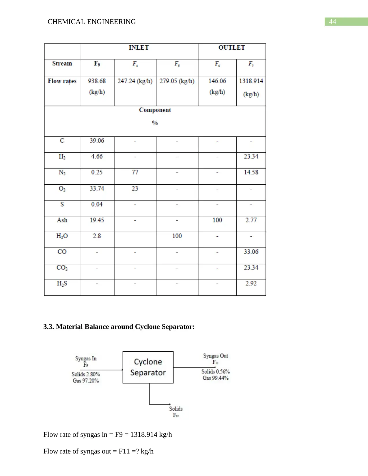
44CHEMICAL ENGINEERING
3.3. Material Balance around Cyclone Separator:
Flow rate of syngas in = F9 = 1318.914 kg/h
Flow rate of syngas out = F11 =? kg/h
3.3. Material Balance around Cyclone Separator:
Flow rate of syngas in = F9 = 1318.914 kg/h
Flow rate of syngas out = F11 =? kg/h
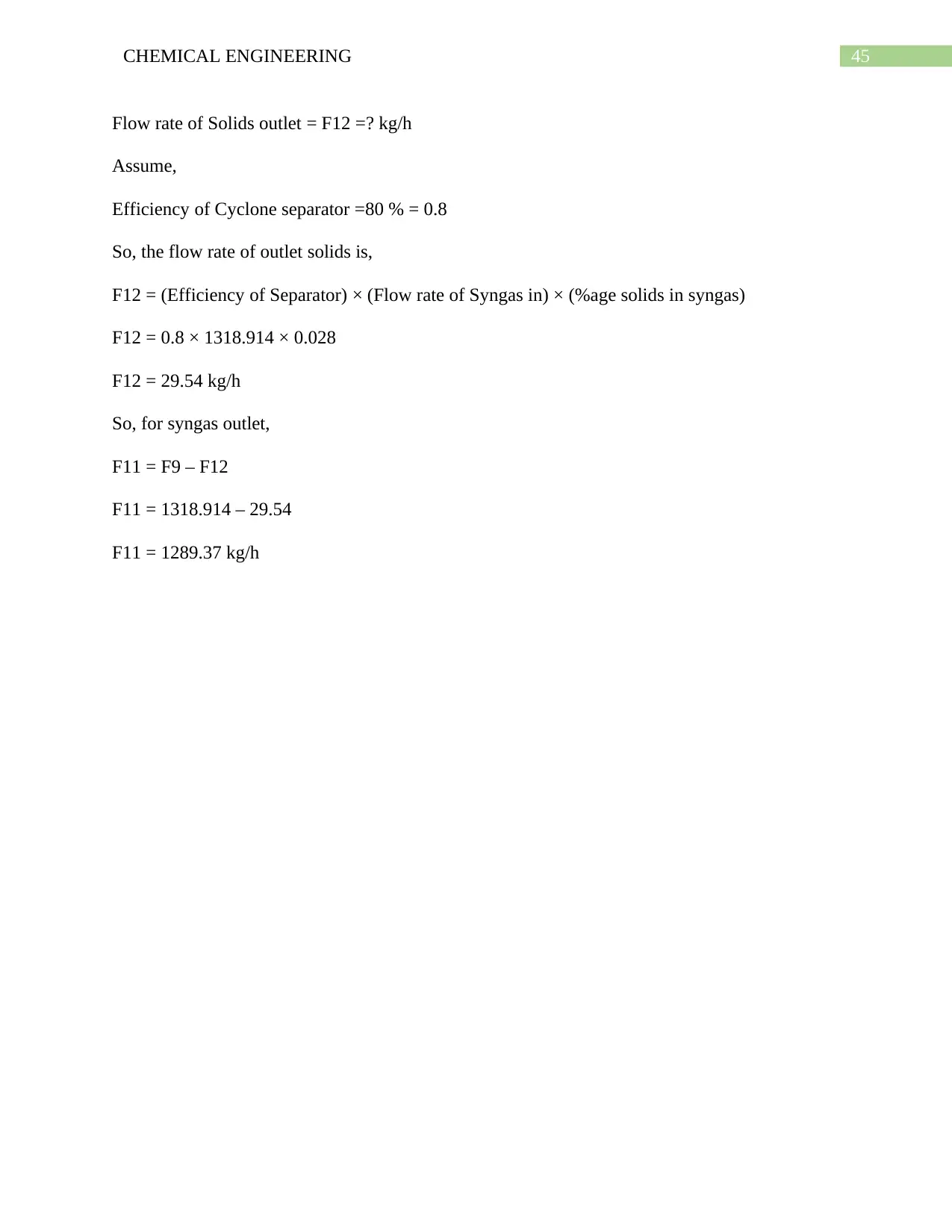
45CHEMICAL ENGINEERING
Flow rate of Solids outlet = F12 =? kg/h
Assume,
Efficiency of Cyclone separator =80 % = 0.8
So, the flow rate of outlet solids is,
F12 = (Efficiency of Separator) × (Flow rate of Syngas in) × (%age solids in syngas)
F12 = 0.8 × 1318.914 × 0.028
F12 = 29.54 kg/h
So, for syngas outlet,
F11 = F9 – F12
F11 = 1318.914 – 29.54
F11 = 1289.37 kg/h
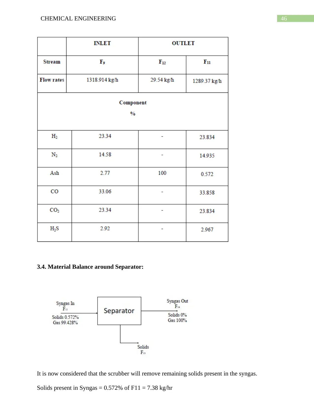
46CHEMICAL ENGINEERING
3.4. Material Balance around Separator:
It is now considered that the scrubber will remove remaining solids present in the syngas.
Solids present in Syngas = 0.572% of F11 = 7.38 kg/hr
3.4. Material Balance around Separator:
It is now considered that the scrubber will remove remaining solids present in the syngas.
Solids present in Syngas = 0.572% of F11 = 7.38 kg/hr
Secure Best Marks with AI Grader
Need help grading? Try our AI Grader for instant feedback on your assignments.
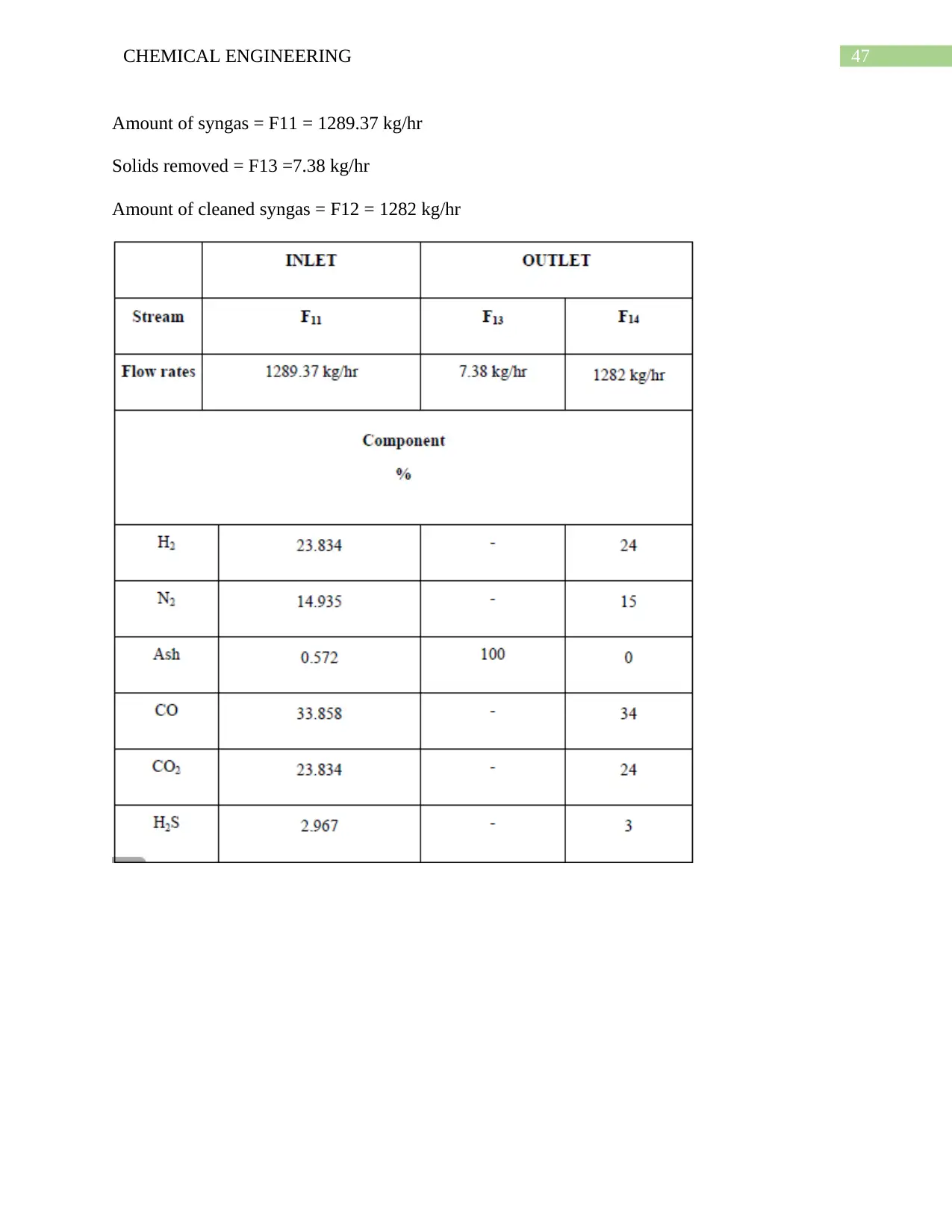
47CHEMICAL ENGINEERING
Amount of syngas = F11 = 1289.37 kg/hr
Solids removed = F13 =7.38 kg/hr
Amount of cleaned syngas = F12 = 1282 kg/hr
Amount of syngas = F11 = 1289.37 kg/hr
Solids removed = F13 =7.38 kg/hr
Amount of cleaned syngas = F12 = 1282 kg/hr

48CHEMICAL ENGINEERING
CHAPTER NO 4
ENERGY BALANCE
CHAPTER NO 4
ENERGY BALANCE
49CHEMICAL ENGINEERING
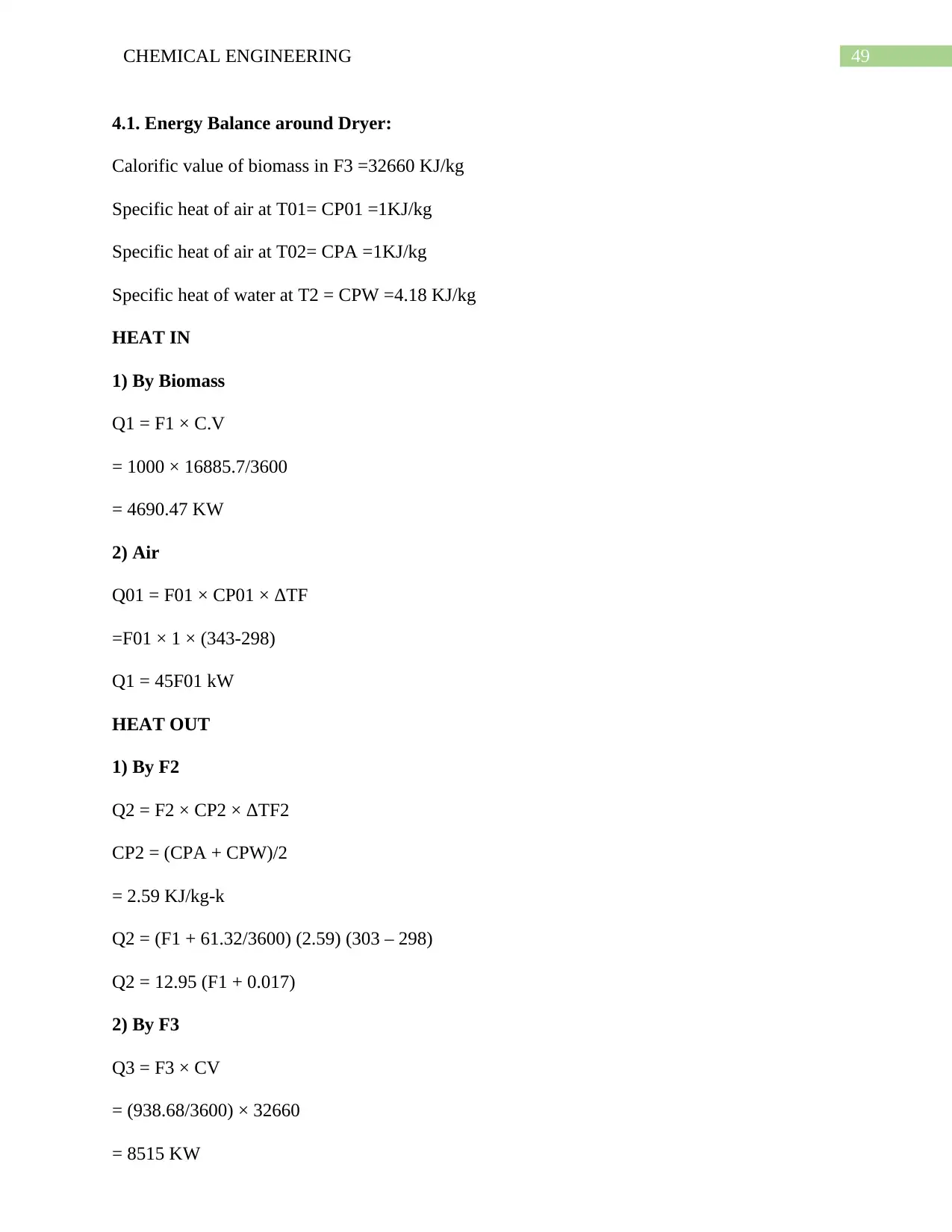
4.1. Energy Balance around Dryer:
Calorific value of biomass in F3 =32660 KJ/kg
Specific heat of air at T01= CP01 =1KJ/kg
Specific heat of air at T02= CPA =1KJ/kg
Specific heat of water at T2 = CPW =4.18 KJ/kg
HEAT IN
1) By Biomass
Q1 = F1 × C.V
= 1000 × 16885.7/3600
= 4690.47 KW
2) Air
Q01 = F01 × CP01 × ΔTF
=F01 × 1 × (343-298)
Q1 = 45F01 kW
HEAT OUT
1) By F2
Q2 = F2 × CP2 × ΔTF2
CP2 = (CPA + CPW)/2
= 2.59 KJ/kg-k
Q2 = (F1 + 61.32/3600) (2.59) (303 – 298)
Q2 = 12.95 (F1 + 0.017)
2) By F3
Q3 = F3 × CV
= (938.68/3600) × 32660
= 8515 KW
Paraphrase This Document
Need a fresh take? Get an instant paraphrase of this document with our AI Paraphraser
50CHEMICAL ENGINEERING
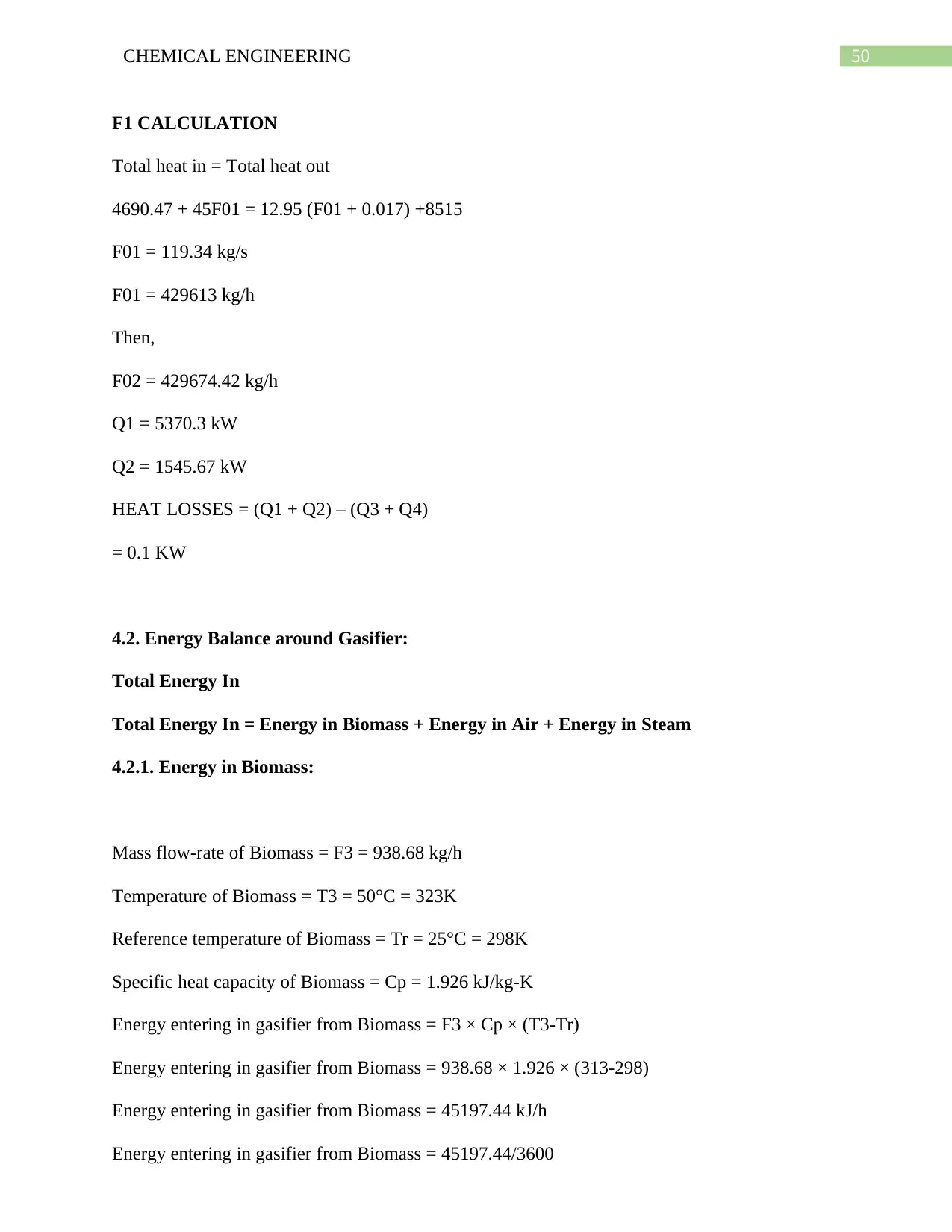
F1 CALCULATION
Total heat in = Total heat out
4690.47 + 45F01 = 12.95 (F01 + 0.017) +8515
F01 = 119.34 kg/s
F01 = 429613 kg/h
Then,
F02 = 429674.42 kg/h
Q1 = 5370.3 kW
Q2 = 1545.67 kW
HEAT LOSSES = (Q1 + Q2) – (Q3 + Q4)
= 0.1 KW
4.2. Energy Balance around Gasifier:
Total Energy In
Total Energy In = Energy in Biomass + Energy in Air + Energy in Steam
4.2.1. Energy in Biomass:
Mass flow-rate of Biomass = F3 = 938.68 kg/h
Temperature of Biomass = T3 = 50°C = 323K
Reference temperature of Biomass = Tr = 25°C = 298K
Specific heat capacity of Biomass = Cp = 1.926 kJ/kg-K
Energy entering in gasifier from Biomass = F3 × Cp × (T3-Tr)
Energy entering in gasifier from Biomass = 938.68 × 1.926 × (313-298)
Energy entering in gasifier from Biomass = 45197.44 kJ/h
Energy entering in gasifier from Biomass = 45197.44/3600
51CHEMICAL ENGINEERING
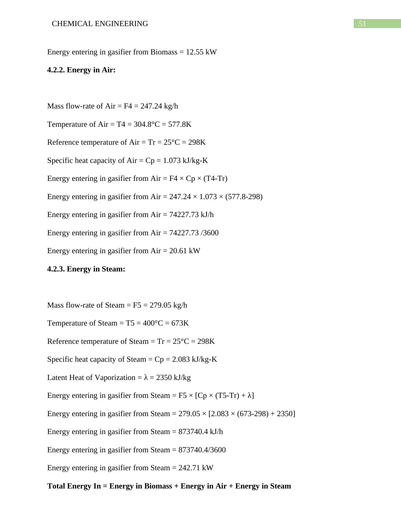
Energy entering in gasifier from Biomass = 12.55 kW
4.2.2. Energy in Air:
Mass flow-rate of Air = F4 = 247.24 kg/h
Temperature of Air = T4 = 304.8°C = 577.8K
Reference temperature of Air = Tr = 25°C = 298K
Specific heat capacity of Air = Cp = 1.073 kJ/kg-K
Energy entering in gasifier from Air = F4 × Cp × (T4-Tr)
Energy entering in gasifier from Air = 247.24 × 1.073 × (577.8-298)
Energy entering in gasifier from Air = 74227.73 kJ/h
Energy entering in gasifier from Air = 74227.73 /3600
Energy entering in gasifier from Air = 20.61 kW
4.2.3. Energy in Steam:
Mass flow-rate of Steam = F5 = 279.05 kg/h
Temperature of Steam = T5 = 400°C = 673K
Reference temperature of Steam = Tr = 25°C = 298K
Specific heat capacity of Steam = Cp = 2.083 kJ/kg-K
Latent Heat of Vaporization = λ = 2350 kJ/kg
Energy entering in gasifier from Steam = F5 × [Cp × (T5-Tr) + λ]
Energy entering in gasifier from Steam = 279.05 × [2.083 × (673-298) + 2350]
Energy entering in gasifier from Steam = 873740.4 kJ/h
Energy entering in gasifier from Steam = 873740.4/3600
Energy entering in gasifier from Steam = 242.71 kW
Total Energy In = Energy in Biomass + Energy in Air + Energy in Steam
52CHEMICAL ENGINEERING
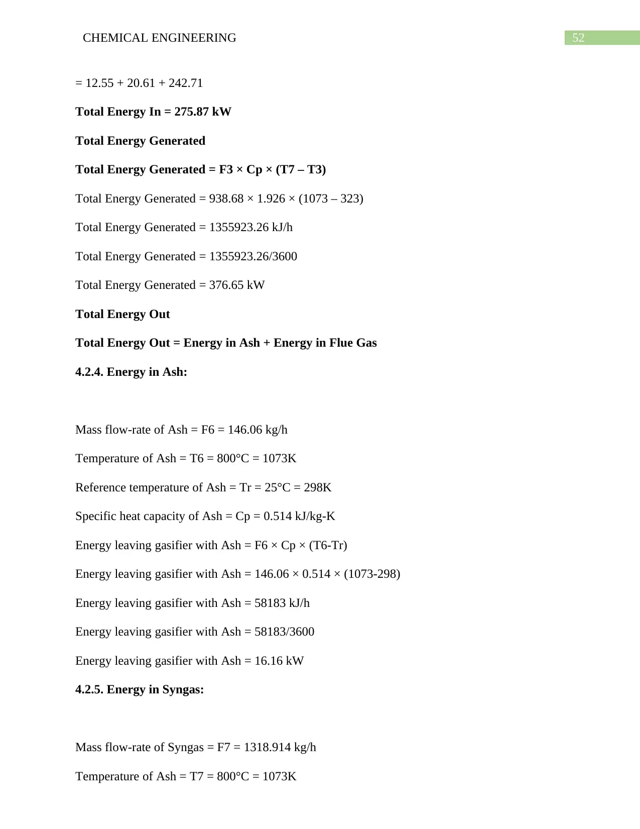
= 12.55 + 20.61 + 242.71
Total Energy In = 275.87 kW
Total Energy Generated
Total Energy Generated = F3 × Cp × (T7 – T3)
Total Energy Generated = 938.68 × 1.926 × (1073 – 323)
Total Energy Generated = 1355923.26 kJ/h
Total Energy Generated = 1355923.26/3600
Total Energy Generated = 376.65 kW
Total Energy Out
Total Energy Out = Energy in Ash + Energy in Flue Gas
4.2.4. Energy in Ash:
Mass flow-rate of Ash = F6 = 146.06 kg/h
Temperature of Ash = T6 = 800°C = 1073K
Reference temperature of Ash = Tr = 25°C = 298K
Specific heat capacity of Ash = Cp = 0.514 kJ/kg-K
Energy leaving gasifier with Ash = F6 × Cp × (T6-Tr)
Energy leaving gasifier with Ash = 146.06 × 0.514 × (1073-298)
Energy leaving gasifier with Ash = 58183 kJ/h
Energy leaving gasifier with Ash = 58183/3600
Energy leaving gasifier with Ash = 16.16 kW
4.2.5. Energy in Syngas:
Mass flow-rate of Syngas = F7 = 1318.914 kg/h
Temperature of Ash = T7 = 800°C = 1073K
Secure Best Marks with AI Grader
Need help grading? Try our AI Grader for instant feedback on your assignments.
53CHEMICAL ENGINEERING
Reference temperature of Ash = Tr = 25°C = 298K
Specific heat capacity of Ash = Cp = 2.22 kJ/kg-K
Energy leaving gasifier with Ash = F7 × Cp × (T7-Tr)
Energy leaving gasifier with Ash = 1318.914 × 2.22 × (1073-298)
Energy leaving gasifier with Ash = 2269191.537 kJ/h
Energy leaving gasifier with Ash = 2269191.537/3600
Energy leaving gasifier with Ash = 630.33 kW
Total Energy Out = Energy in Ash + Energy in Syngas
= 16.16 + 630.33
Total Energy Out = 646.49 kW
4.2.6. Overall Energy Balance:
Energy Loss = Total Energy in – Total Energy Out + Total Energy Generated
Energy Loss = 275.87 – 646.49 + 376.65
Energy Loss = 6.03 kW
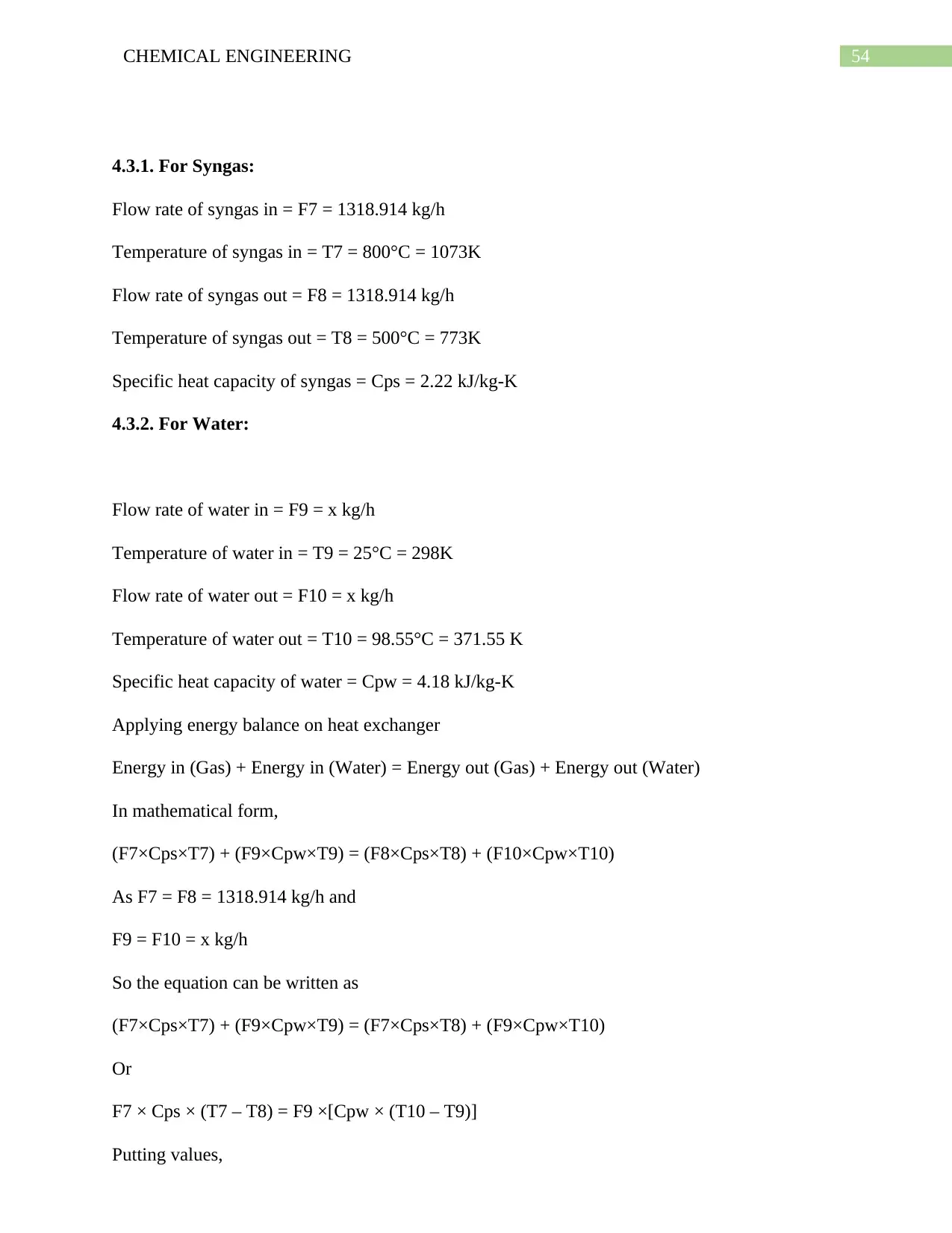
4.3. Energy Balance around Heat Exchanger:
54CHEMICAL ENGINEERING
4.3.1. For Syngas:
Flow rate of syngas in = F7 = 1318.914 kg/h
Temperature of syngas in = T7 = 800°C = 1073K
Flow rate of syngas out = F8 = 1318.914 kg/h
Temperature of syngas out = T8 = 500°C = 773K
Specific heat capacity of syngas = Cps = 2.22 kJ/kg-K
4.3.2. For Water:
Flow rate of water in = F9 = x kg/h
Temperature of water in = T9 = 25°C = 298K
Flow rate of water out = F10 = x kg/h
Temperature of water out = T10 = 98.55°C = 371.55 K
Specific heat capacity of water = Cpw = 4.18 kJ/kg-K
Applying energy balance on heat exchanger
Energy in (Gas) + Energy in (Water) = Energy out (Gas) + Energy out (Water)
In mathematical form,
(F7×Cps×T7) + (F9×Cpw×T9) = (F8×Cps×T8) + (F10×Cpw×T10)
As F7 = F8 = 1318.914 kg/h and
F9 = F10 = x kg/h
So the equation can be written as
(F7×Cps×T7) + (F9×Cpw×T9) = (F7×Cps×T8) + (F9×Cpw×T10)
Or
F7 × Cps × (T7 – T8) = F9 ×[Cpw × (T10 – T9)]
Putting values,
55CHEMICAL ENGINEERING
1318.914 × 2.22 × (1073 – 773) = x × [4.18 × (371.55 – 298)]
x = 2857.141 kg/h
So,
F9 = 2857.141 kg/h
F10 = 2857.141 kg/h
So, heat in gas,
Qs = F7 × Cps × (T7 – T8)
Qs = 1318.914 × 2.22 × (1073 – 773)
Qs = 878396.724 kJ/h
Qs = 878396.724/3600
Qs = 244 kW
So, heat in gas,
Qw = F9 ×[Cpw × (T10 – T9)]
Qw = 2857.141 × [4.18 × (371.55 – 298)]
Qw = 878396.57 kJ/h
Qw = 878396.57/3600
Qw = 244 kW
Energy Balance Around Heat Exchanger
Energy In
Stream Flow rate (kg/hr) Cp (kJ/kg-
K)
T(K) Q = F × Cp × (T-
Tr)
Syngas 1318.914 2.22 1073 630.33
Water 2857.141 4.18 298 0
Total Energy In = 630.33 kW
Stream Flow rate (kg/hr) Cp (kJ/kg-
K)
T(K) Q = F × Cp × (T-
Tr)
Paraphrase This Document
Need a fresh take? Get an instant paraphrase of this document with our AI Paraphraser
56CHEMICAL ENGINEERING
Syngas 1318.914 2.22 773 386.33
Water 2857.141 4.18 371.55 244
Total Energy Out = 630.33 kW
CHAPTER NO 5
EQUIPMENT DESIGN
Syngas 1318.914 2.22 773 386.33
Water 2857.141 4.18 371.55 244
Total Energy Out = 630.33 kW
CHAPTER NO 5
EQUIPMENT DESIGN
57CHEMICAL ENGINEERING
5.1. Design of Gasifier:
DESIGN OF GASIFIER
Operating Conditions
Operating temperature = 1273 K
Operating pressure = 600 psi
1. Chemical Reactions
Below are the list of Chief reactions which are taking place inside the gasifier:
1. C + CO2 = 2CO
2. CO + H2O = CO2 + H2
3. C + H2O= CO + H2
Rate Determining Step:
According to the Thermodynamic study of these reactions the slowest step is reaction (3). So it
can be stated that it would be rate determining step.
C + H2O CO + H2
Order of Reaction:
The order of reaction is 2
Considering the selected gasifier shows behavior to that of a plug flow reactor.
For Plug Flow Reactor:
If the order of reaction is 2 then performance equation for PFR is;
τ = ∫ ∫
CA
CAO
dCA/(-rA) ………………………………….(A)
-rA = kCA2 …………………………………………..(B)
Here,
CA = initial concentration (kmol/m3)
CA0 = final concentration (kmol/m3)
k = rate constant
58CHEMICAL ENGINEERING
-rA = reaction rate (kmol/m3.s)
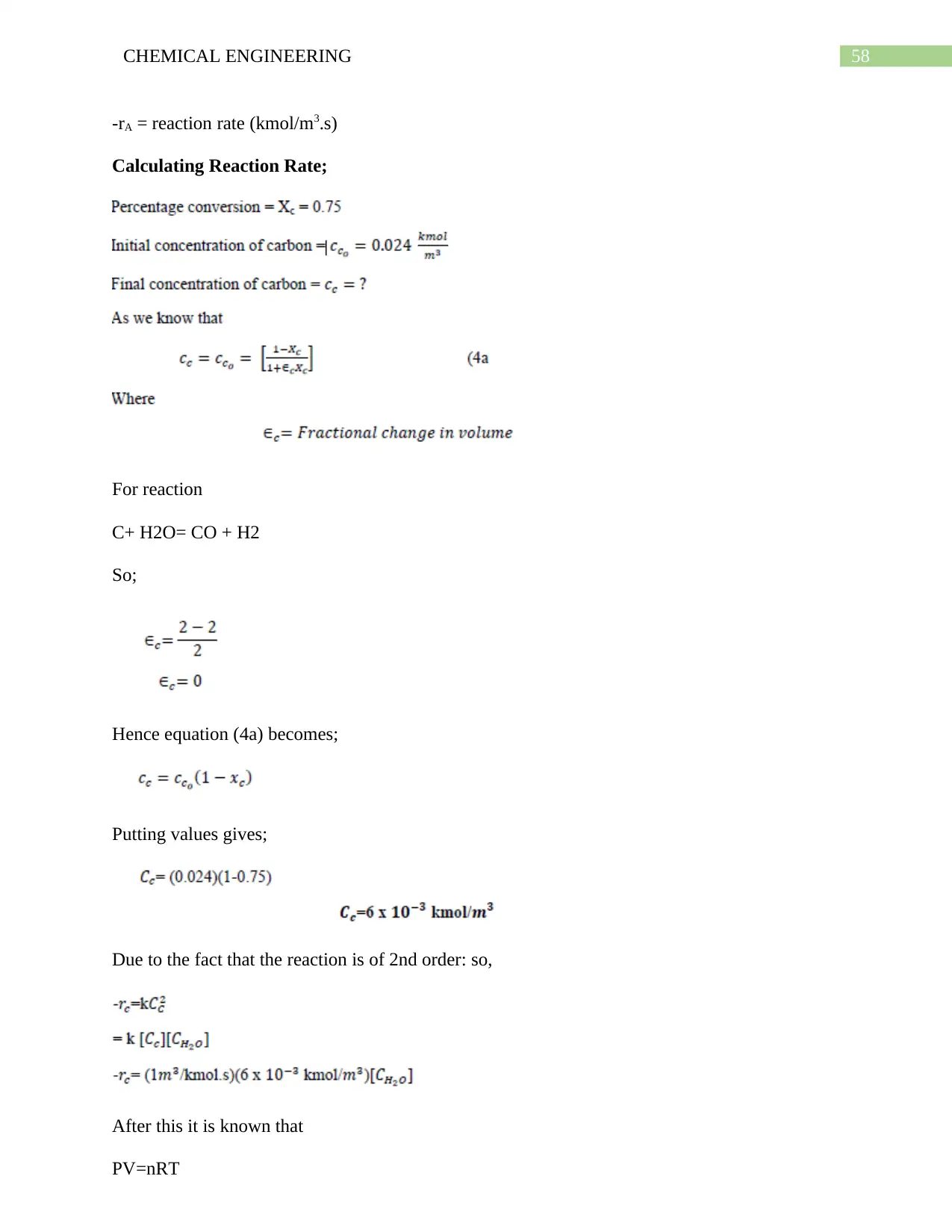
Calculating Reaction Rate;
For reaction
C+ H2O= CO + H2
So;
Hence equation (4a) becomes;
Putting values gives;
Due to the fact that the reaction is of 2nd order: so,
After this it is known that
PV=nRT
-rA = reaction rate (kmol/m3.s)
Calculating Reaction Rate;
For reaction
C+ H2O= CO + H2
So;
Hence equation (4a) becomes;
Putting values gives;
Due to the fact that the reaction is of 2nd order: so,
After this it is known that
PV=nRT
Secure Best Marks with AI Grader
Need help grading? Try our AI Grader for instant feedback on your assignments.
59CHEMICAL ENGINEERING
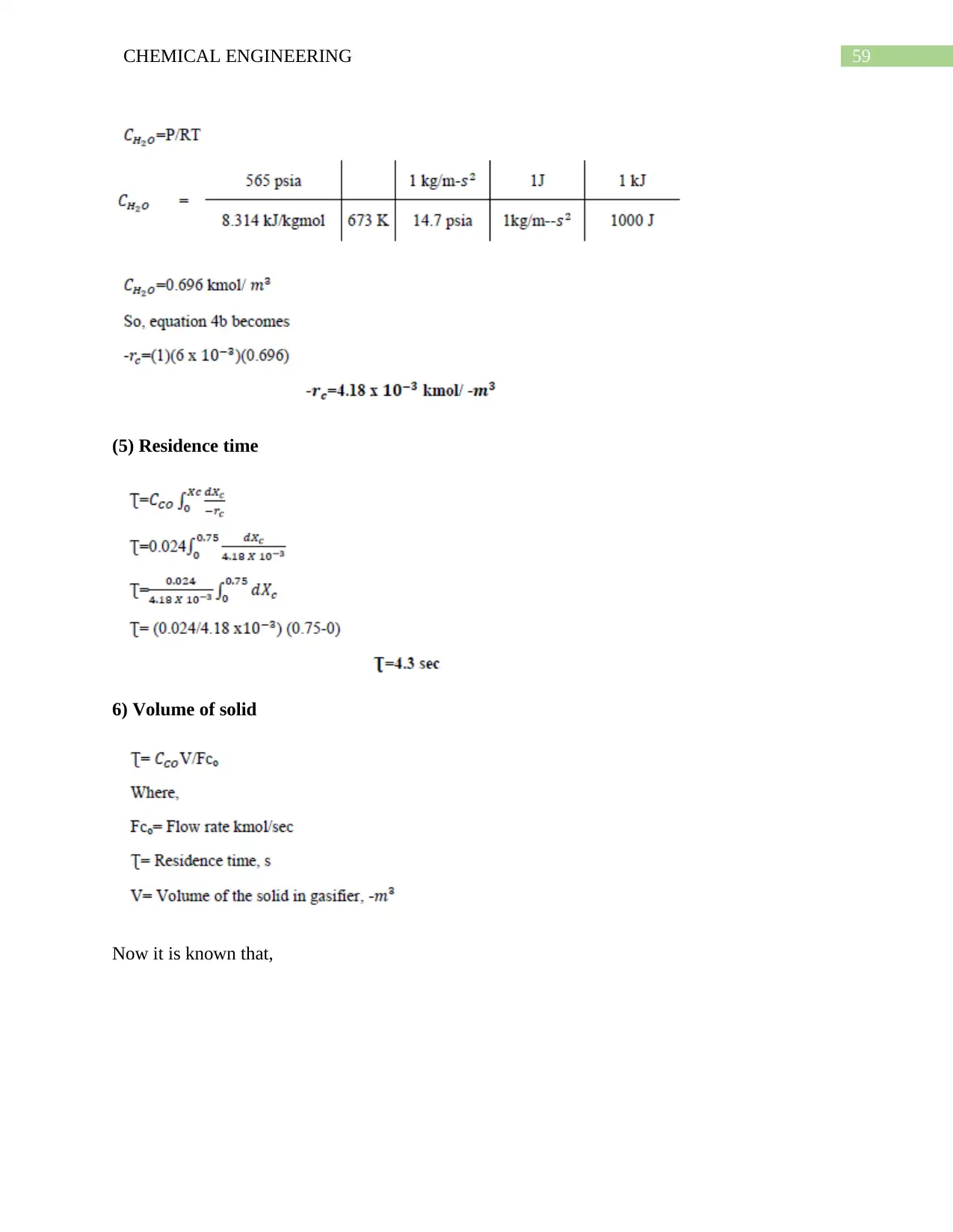
(5) Residence time
6) Volume of solid
Now it is known that,
(5) Residence time
6) Volume of solid
Now it is known that,
60CHEMICAL ENGINEERING
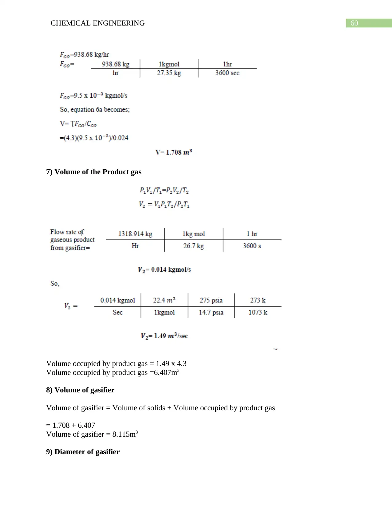
7) Volume of the Product gas
Volume occupied by product gas = 1.49 x 4.3
Volume occupied by product gas =6.407m3
8) Volume of gasifier
Volume of gasifier = Volume of solids + Volume occupied by product gas
= 1.708 + 6.407
Volume of gasifier = 8.115m3
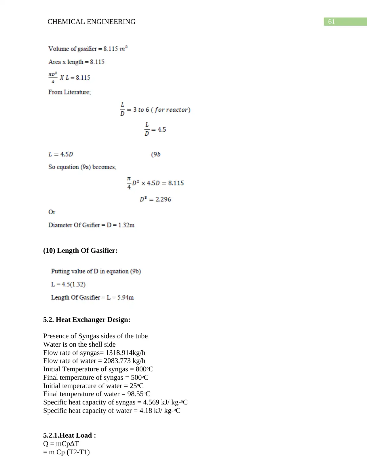
9) Diameter of gasifier
7) Volume of the Product gas
Volume occupied by product gas = 1.49 x 4.3
Volume occupied by product gas =6.407m3
8) Volume of gasifier
Volume of gasifier = Volume of solids + Volume occupied by product gas
= 1.708 + 6.407
Volume of gasifier = 8.115m3
9) Diameter of gasifier
61CHEMICAL ENGINEERING
(10) Length Of Gasifier:
5.2. Heat Exchanger Design:
Presence of Syngas sides of the tube
Water is on the shell side
Flow rate of syngas= 1318.914kg/h
Flow rate of water = 2083.773 kg/h
Initial Temperature of syngas = 800ᵒC
Final temperature of syngas = 500ᵒC
Initial temperature of water = 25ᵒC
Final temperature of water = 98.55ᵒC
Specific heat capacity of syngas = 4.569 kJ/ kg-ᵒC
Specific heat capacity of water = 4.18 kJ/ kg-ᵒC
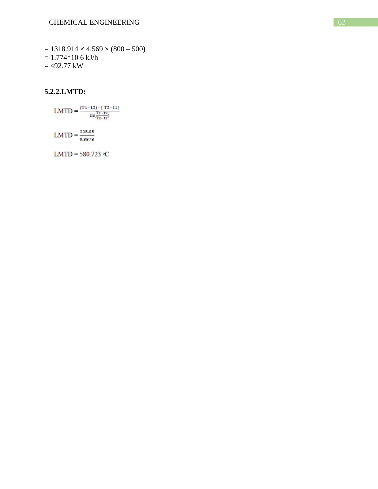
5.2.1.Heat Load :
Q = mCpΔT
= m Cp (T2-T1)
Paraphrase This Document
Need a fresh take? Get an instant paraphrase of this document with our AI Paraphraser
62CHEMICAL ENGINEERING
= 1318.914 × 4.569 × (800 – 500)
= 1.774*10 6 kJ/h
= 492.77 kW
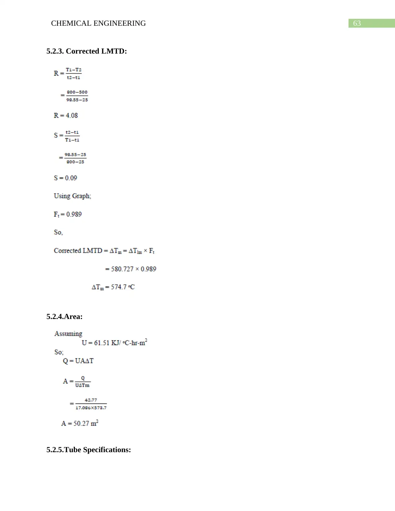
5.2.2.LMTD:
= 1318.914 × 4.569 × (800 – 500)
= 1.774*10 6 kJ/h
= 492.77 kW
5.2.2.LMTD:
63CHEMICAL ENGINEERING
5.2.3. Corrected LMTD:
5.2.4.Area:
5.2.5.Tube Specifications:
5.2.3. Corrected LMTD:
5.2.4.Area:
5.2.5.Tube Specifications:
64CHEMICAL ENGINEERING
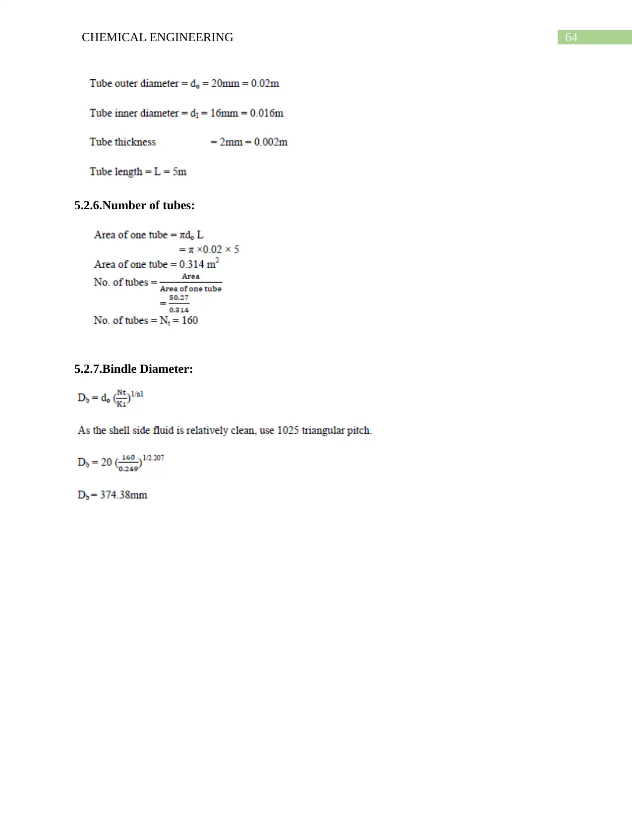
5.2.6.Number of tubes:
5.2.7.Bindle Diameter:
5.2.6.Number of tubes:
5.2.7.Bindle Diameter:
Secure Best Marks with AI Grader
Need help grading? Try our AI Grader for instant feedback on your assignments.
65CHEMICAL ENGINEERING
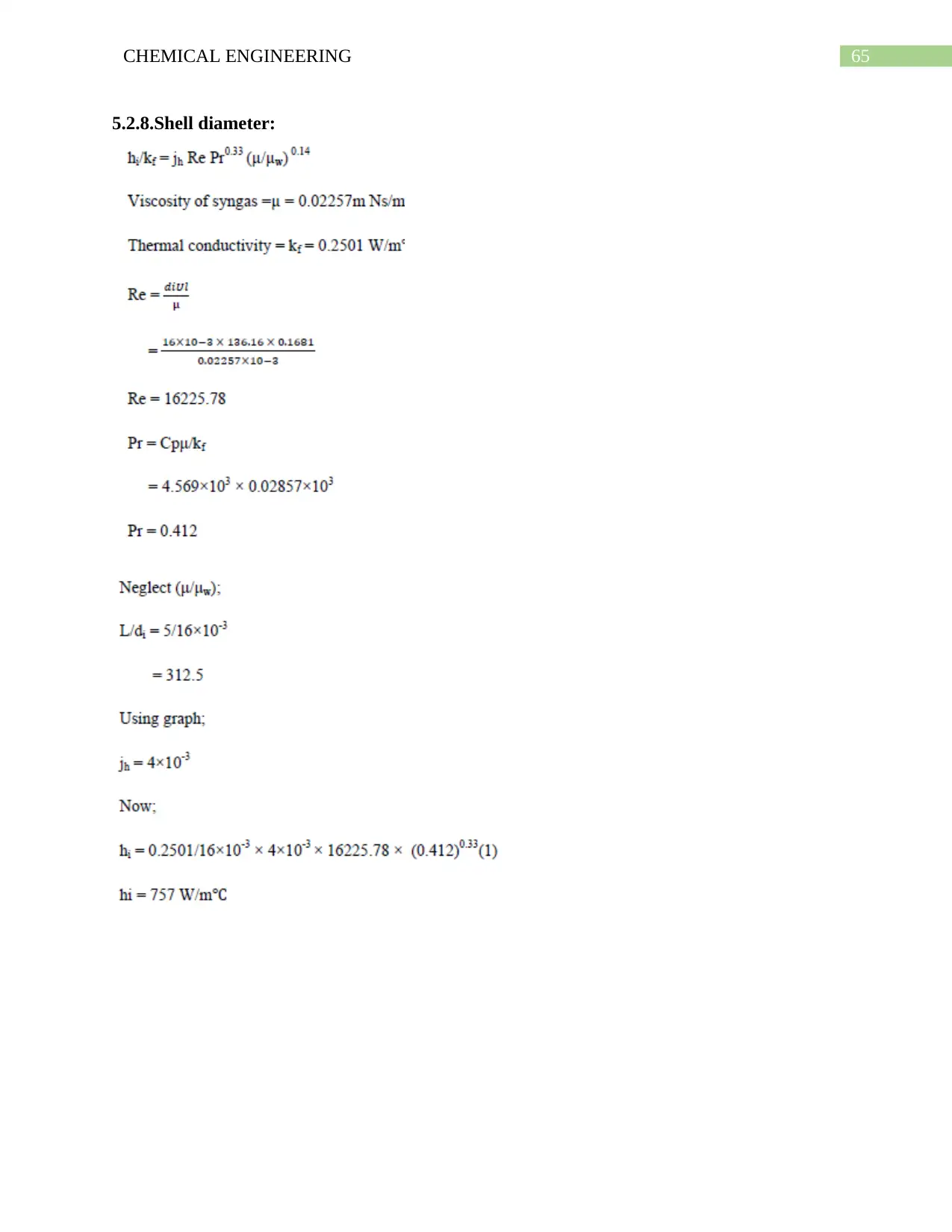
5.2.8.Shell diameter:
5.2.8.Shell diameter:
66CHEMICAL ENGINEERING
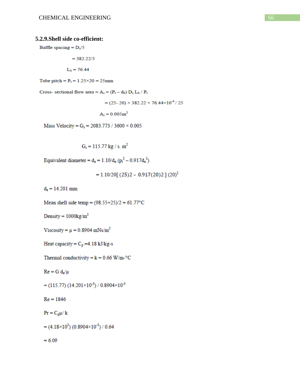
5.2.9.Shell side co-efficient:
5.2.9.Shell side co-efficient:
67CHEMICAL ENGINEERING
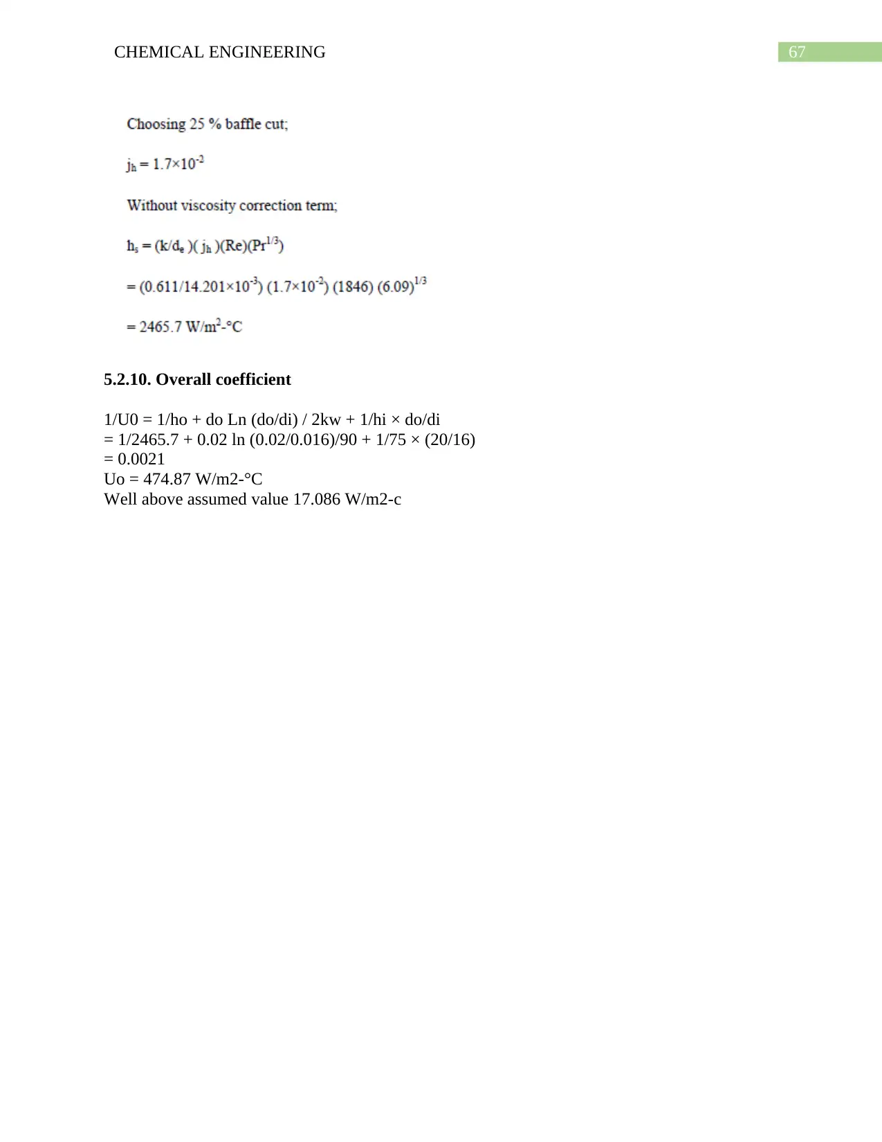
5.2.10. Overall coefficient
1/U0 = 1/ho + do Ln (do/di) / 2kw + 1/hi × do/di
= 1/2465.7 + 0.02 ln (0.02/0.016)/90 + 1/75 × (20/16)
= 0.0021
Uo = 474.87 W/m2-°C
Well above assumed value 17.086 W/m2-c
5.2.10. Overall coefficient
1/U0 = 1/ho + do Ln (do/di) / 2kw + 1/hi × do/di
= 1/2465.7 + 0.02 ln (0.02/0.016)/90 + 1/75 × (20/16)
= 0.0021
Uo = 474.87 W/m2-°C
Well above assumed value 17.086 W/m2-c
Paraphrase This Document
Need a fresh take? Get an instant paraphrase of this document with our AI Paraphraser
68CHEMICAL ENGINEERING
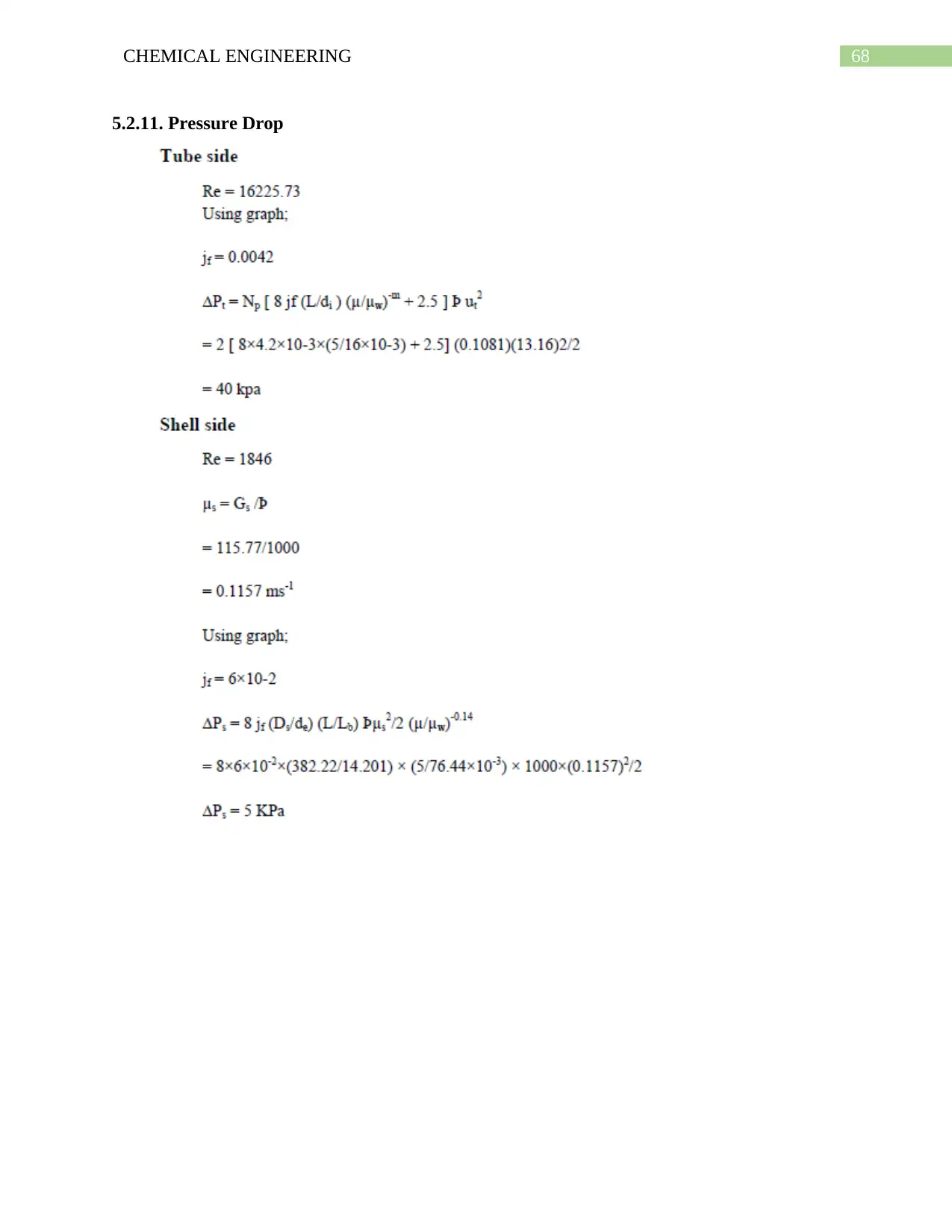
5.2.11. Pressure Drop
5.2.11. Pressure Drop
69CHEMICAL ENGINEERING
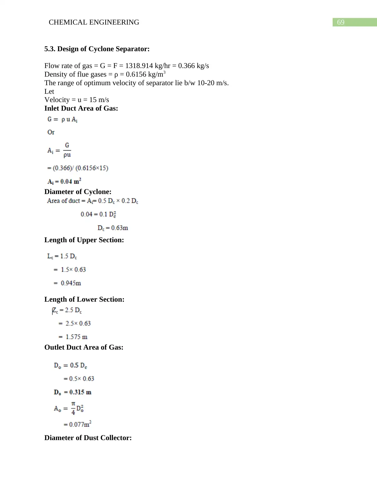
5.3. Design of Cyclone Separator:
Flow rate of gas = G = F = 1318.914 kg/hr = 0.366 kg/s
Density of flue gases = ρ = 0.6156 kg/m3
The range of optimum velocity of separator lie b/w 10-20 m/s.
Let
Velocity = u = 15 m/s
Inlet Duct Area of Gas:
Diameter of Cyclone:
Length of Upper Section:
Length of Lower Section:
Outlet Duct Area of Gas:
Diameter of Dust Collector:
70CHEMICAL ENGINEERING
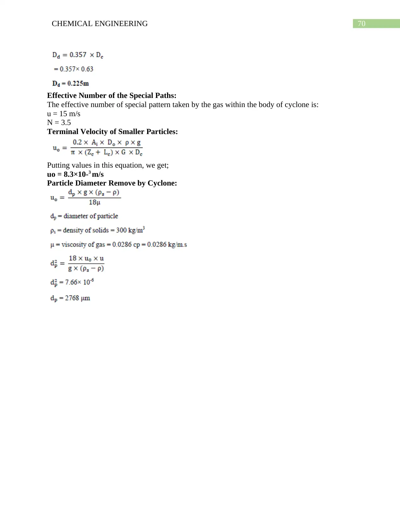
Effective Number of the Special Paths:
The effective number of special pattern taken by the gas within the body of cyclone is:
u = 15 m/s
N = 3.5
Terminal Velocity of Smaller Particles:
Putting values in this equation, we get;
uo = 8.3×10⁻³ m/s
Particle Diameter Remove by Cyclone:
Effective Number of the Special Paths:
The effective number of special pattern taken by the gas within the body of cyclone is:
u = 15 m/s
N = 3.5
Terminal Velocity of Smaller Particles:
Putting values in this equation, we get;
uo = 8.3×10⁻³ m/s
Particle Diameter Remove by Cyclone:
Secure Best Marks with AI Grader
Need help grading? Try our AI Grader for instant feedback on your assignments.

71CHEMICAL ENGINEERING
CHAPTER NO 6
SIMULATION
CHAPTER NO 6
SIMULATION
72CHEMICAL ENGINEERING
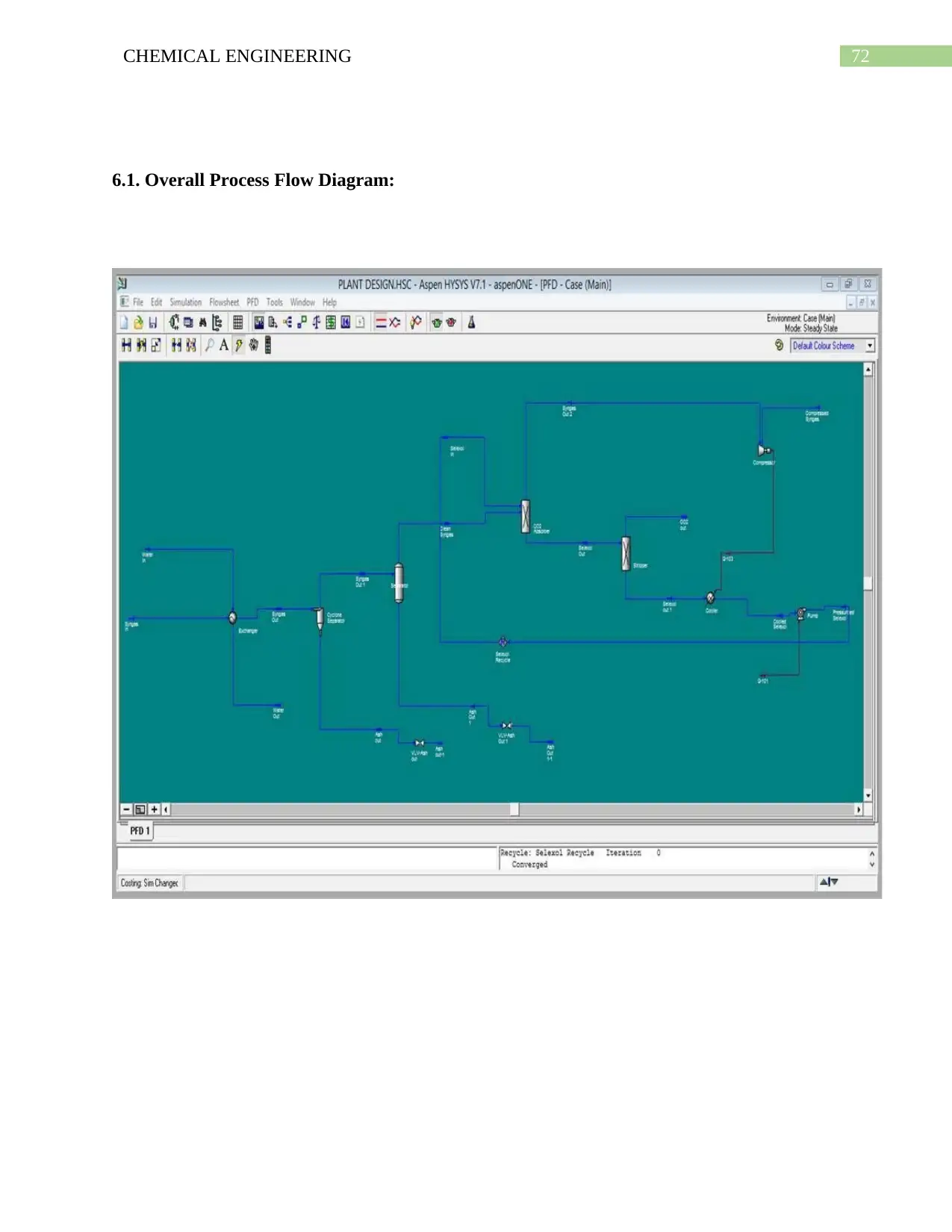
6.1. Overall Process Flow Diagram:
6.1. Overall Process Flow Diagram:
73CHEMICAL ENGINEERING
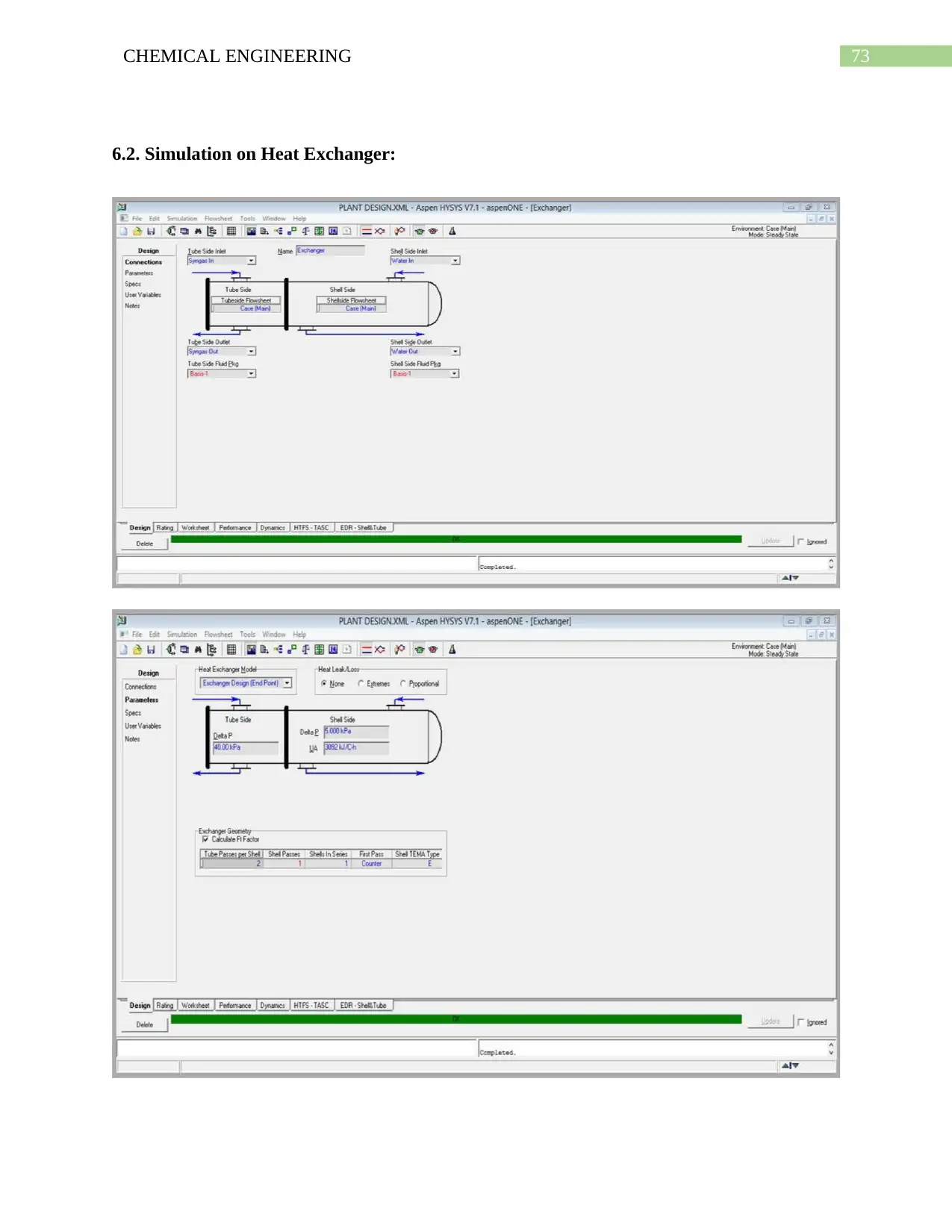
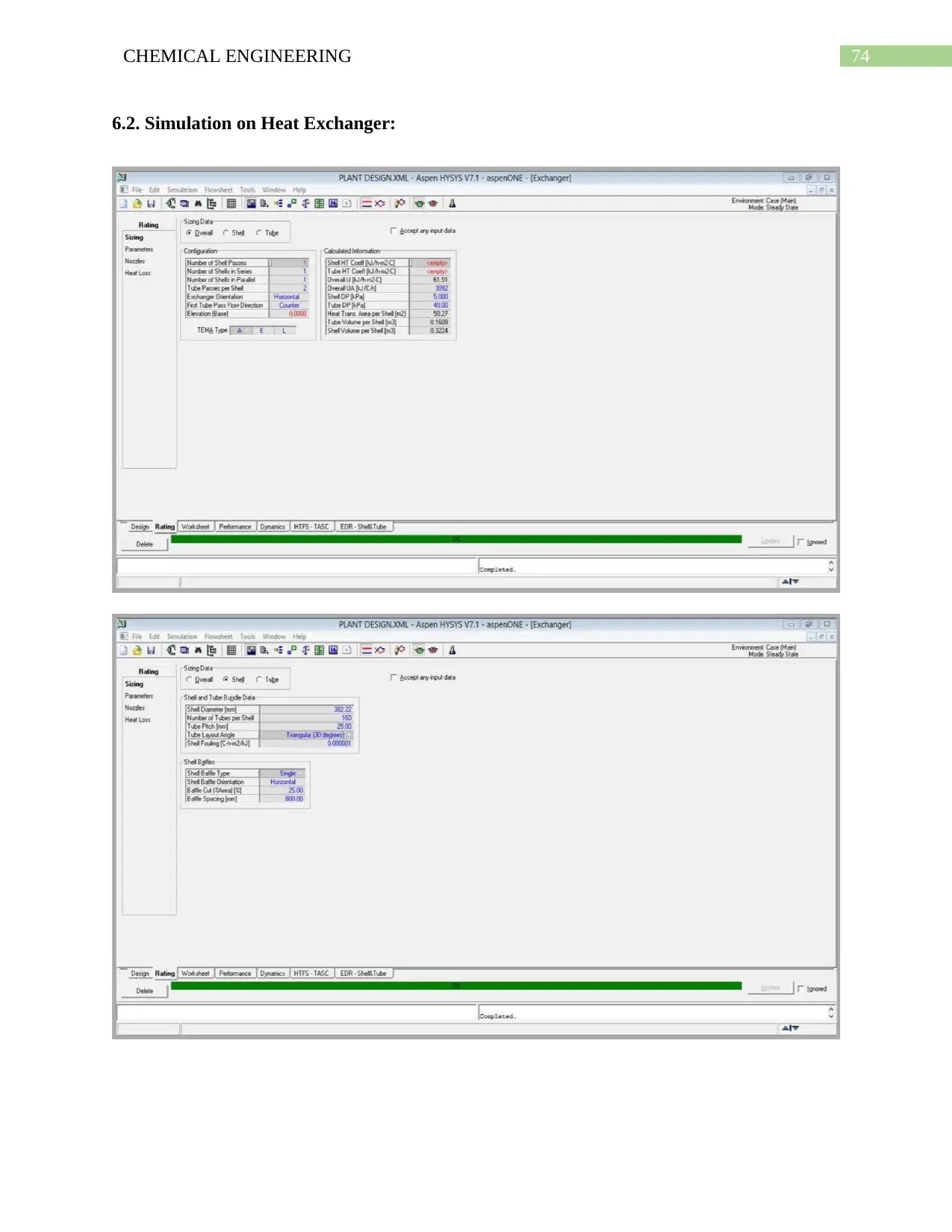
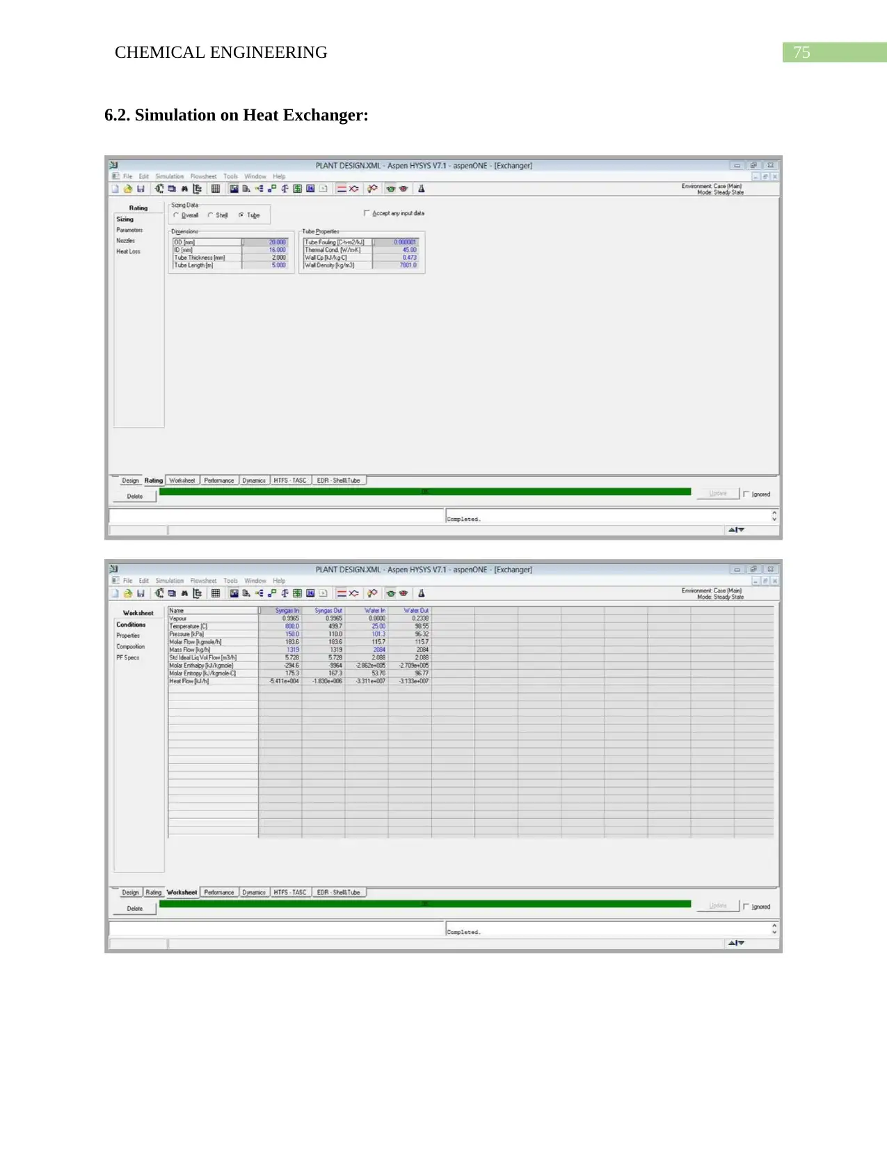
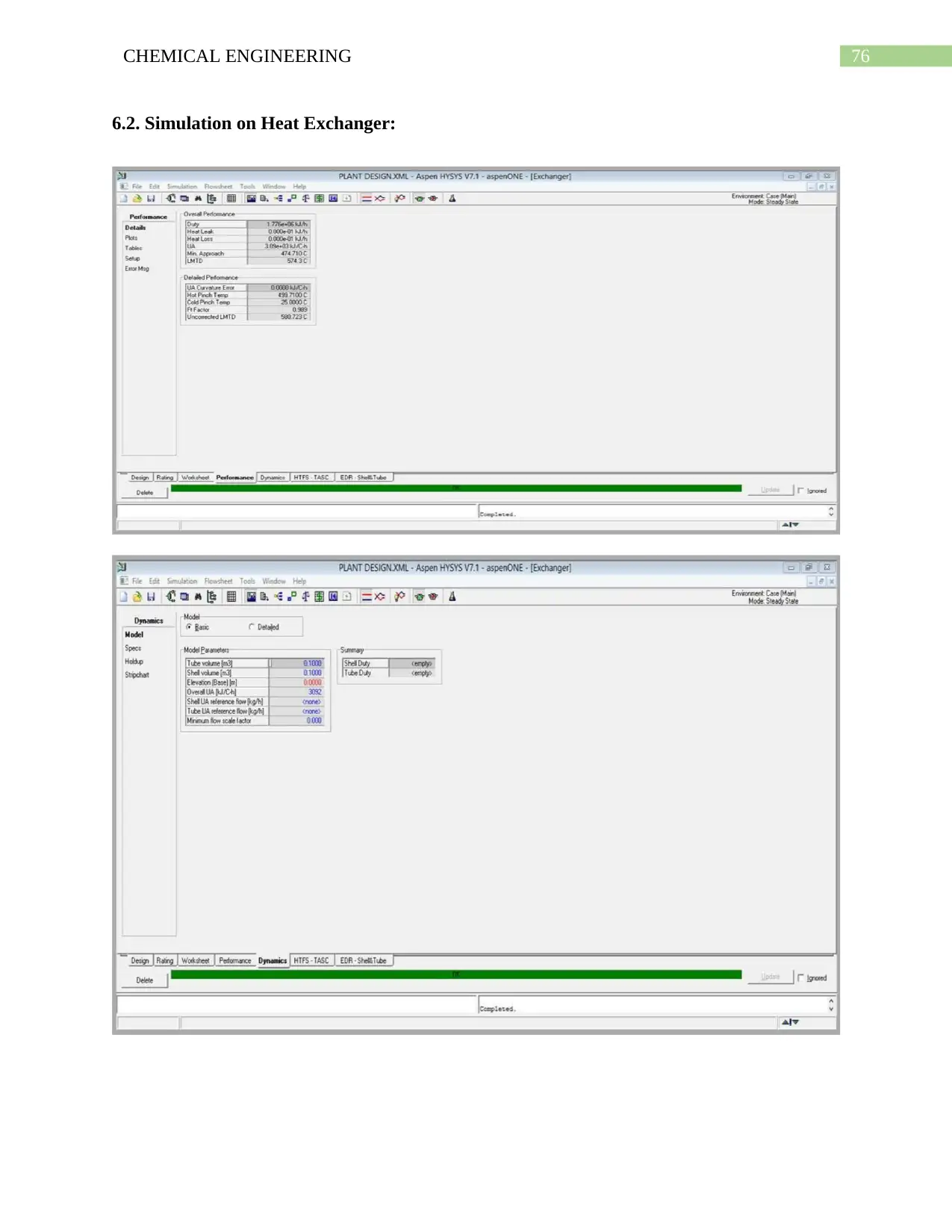
6.2. Simulation on Heat Exchanger:
6.2. Simulation on Heat Exchanger:
Paraphrase This Document
Need a fresh take? Get an instant paraphrase of this document with our AI Paraphraser
74CHEMICAL ENGINEERING
6.2. Simulation on Heat Exchanger:
6.2. Simulation on Heat Exchanger:
75CHEMICAL ENGINEERING
6.2. Simulation on Heat Exchanger:
6.2. Simulation on Heat Exchanger:
76CHEMICAL ENGINEERING
6.2. Simulation on Heat Exchanger:
6.2. Simulation on Heat Exchanger:
Secure Best Marks with AI Grader
Need help grading? Try our AI Grader for instant feedback on your assignments.
77CHEMICAL ENGINEERING
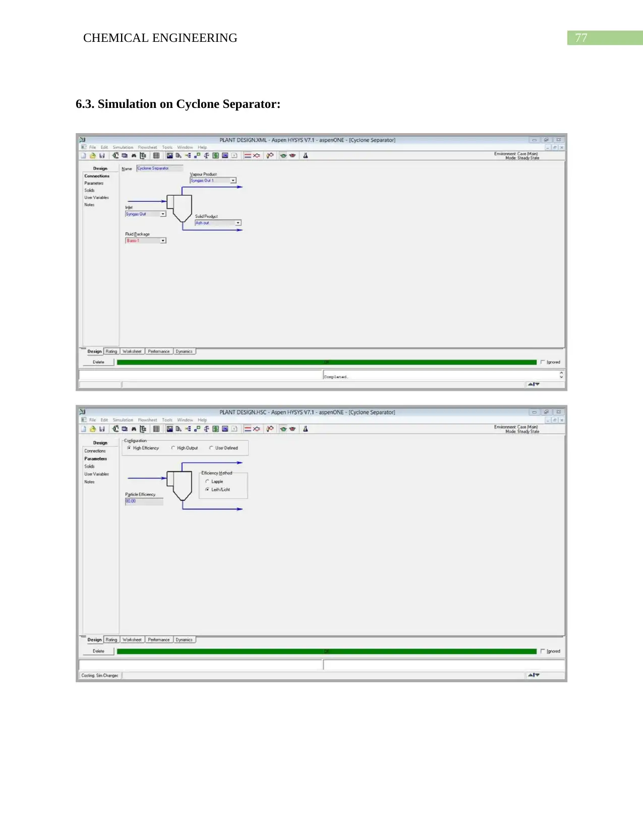
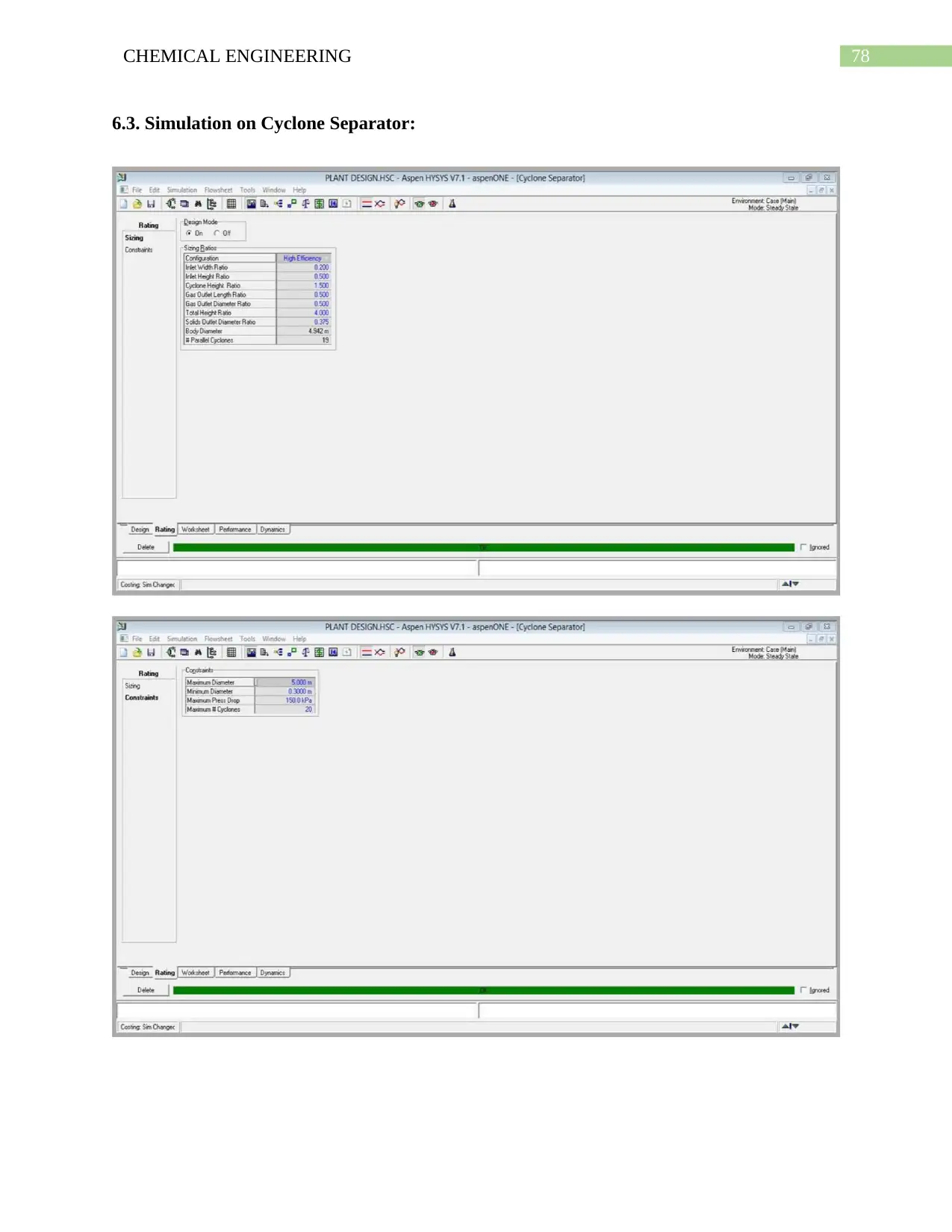
6.3. Simulation on Cyclone Separator:
6.3. Simulation on Cyclone Separator:
78CHEMICAL ENGINEERING
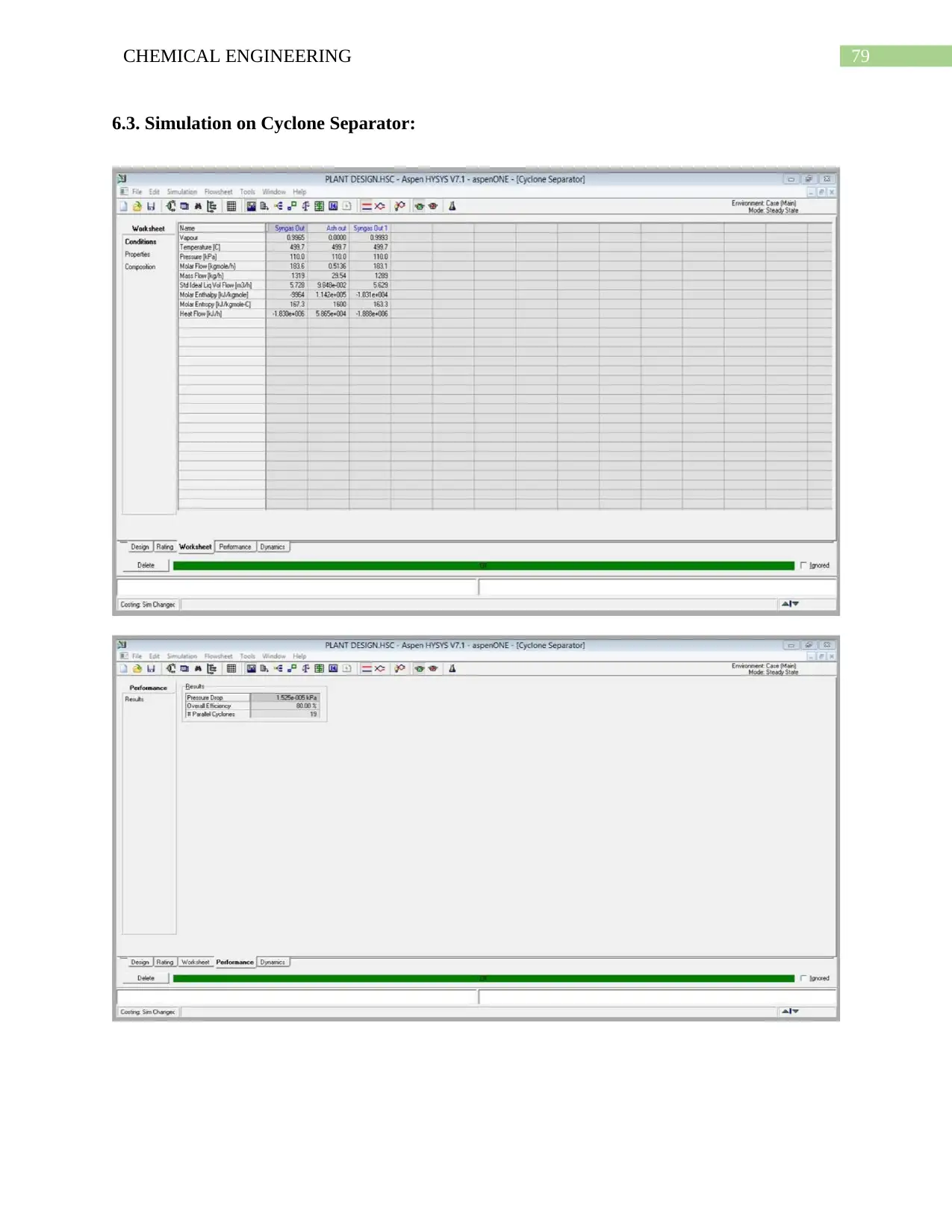
6.3. Simulation on Cyclone Separator:
6.3. Simulation on Cyclone Separator:
79CHEMICAL ENGINEERING
6.3. Simulation on Cyclone Separator:
6.3. Simulation on Cyclone Separator:
Paraphrase This Document
Need a fresh take? Get an instant paraphrase of this document with our AI Paraphraser
80CHEMICAL ENGINEERING
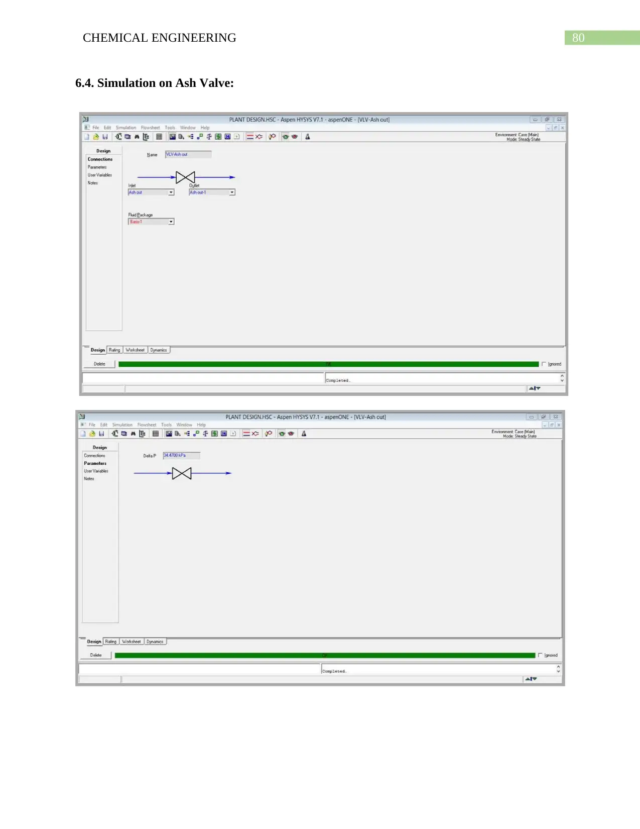
6.4. Simulation on Ash Valve:
6.4. Simulation on Ash Valve:
81CHEMICAL ENGINEERING
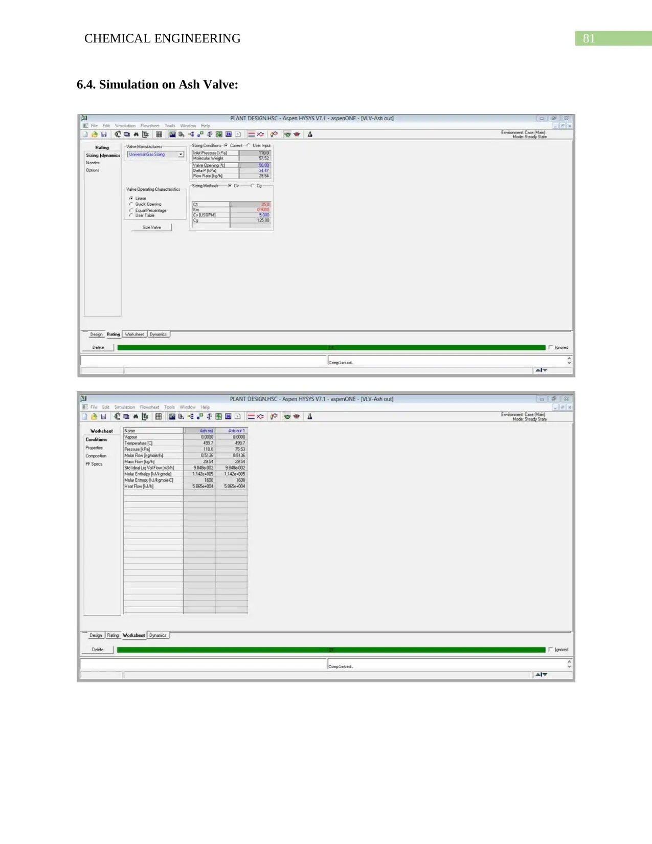
6.4. Simulation on Ash Valve:
6.4. Simulation on Ash Valve:
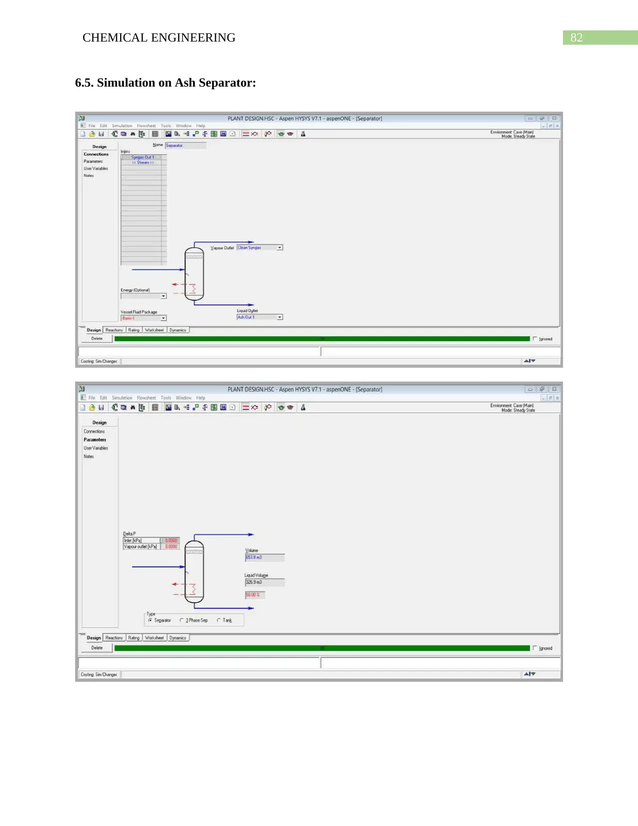
82CHEMICAL ENGINEERING
6.5. Simulation on Ash Separator:
6.5. Simulation on Ash Separator:
Secure Best Marks with AI Grader
Need help grading? Try our AI Grader for instant feedback on your assignments.
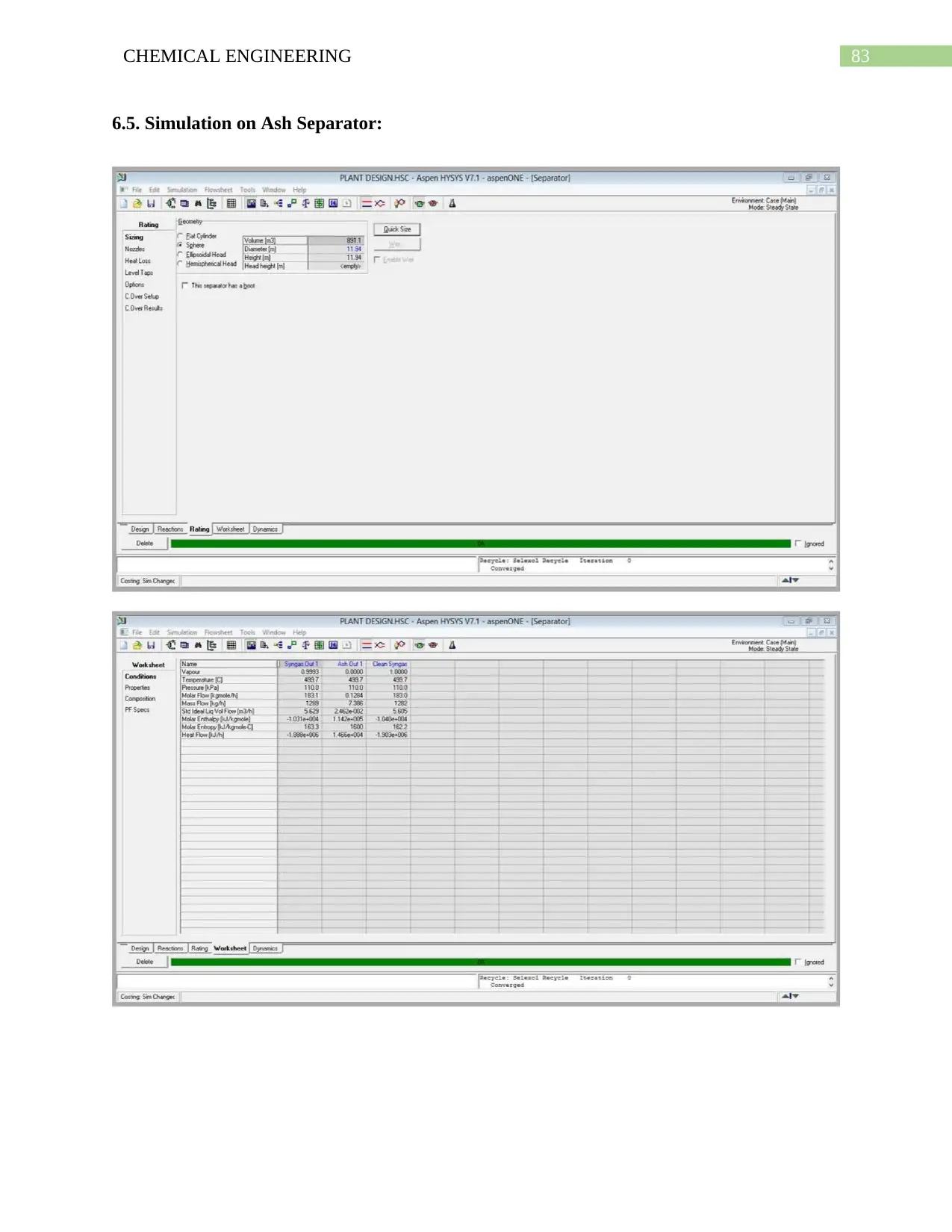
83CHEMICAL ENGINEERING
6.5. Simulation on Ash Separator:
6.5. Simulation on Ash Separator:
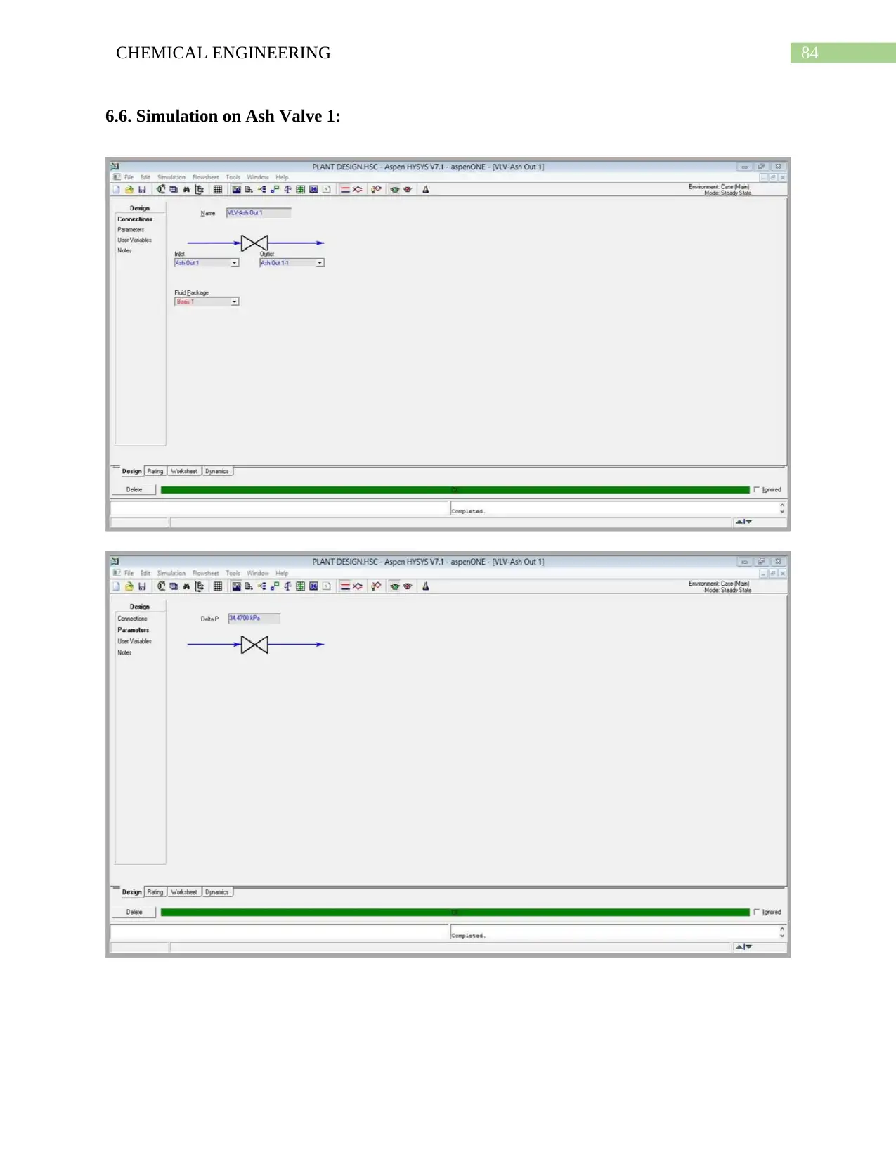
84CHEMICAL ENGINEERING
6.6. Simulation on Ash Valve 1:
6.6. Simulation on Ash Valve 1:
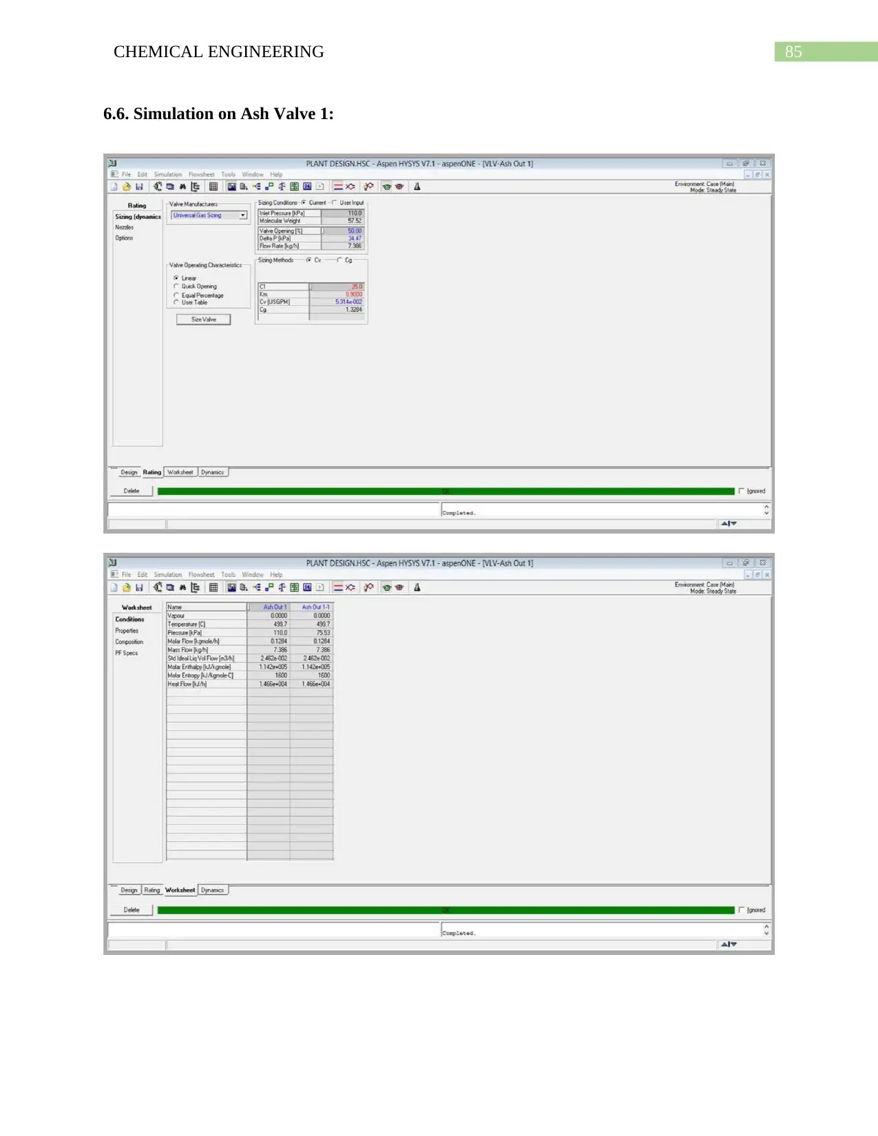
85CHEMICAL ENGINEERING
6.6. Simulation on Ash Valve 1:
6.6. Simulation on Ash Valve 1:
Paraphrase This Document
Need a fresh take? Get an instant paraphrase of this document with our AI Paraphraser
86CHEMICAL ENGINEERING
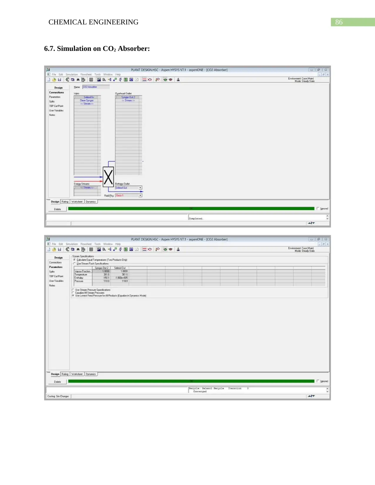
6.7. Simulation on CO2 Absorber:
6.7. Simulation on CO2 Absorber:
87CHEMICAL ENGINEERING
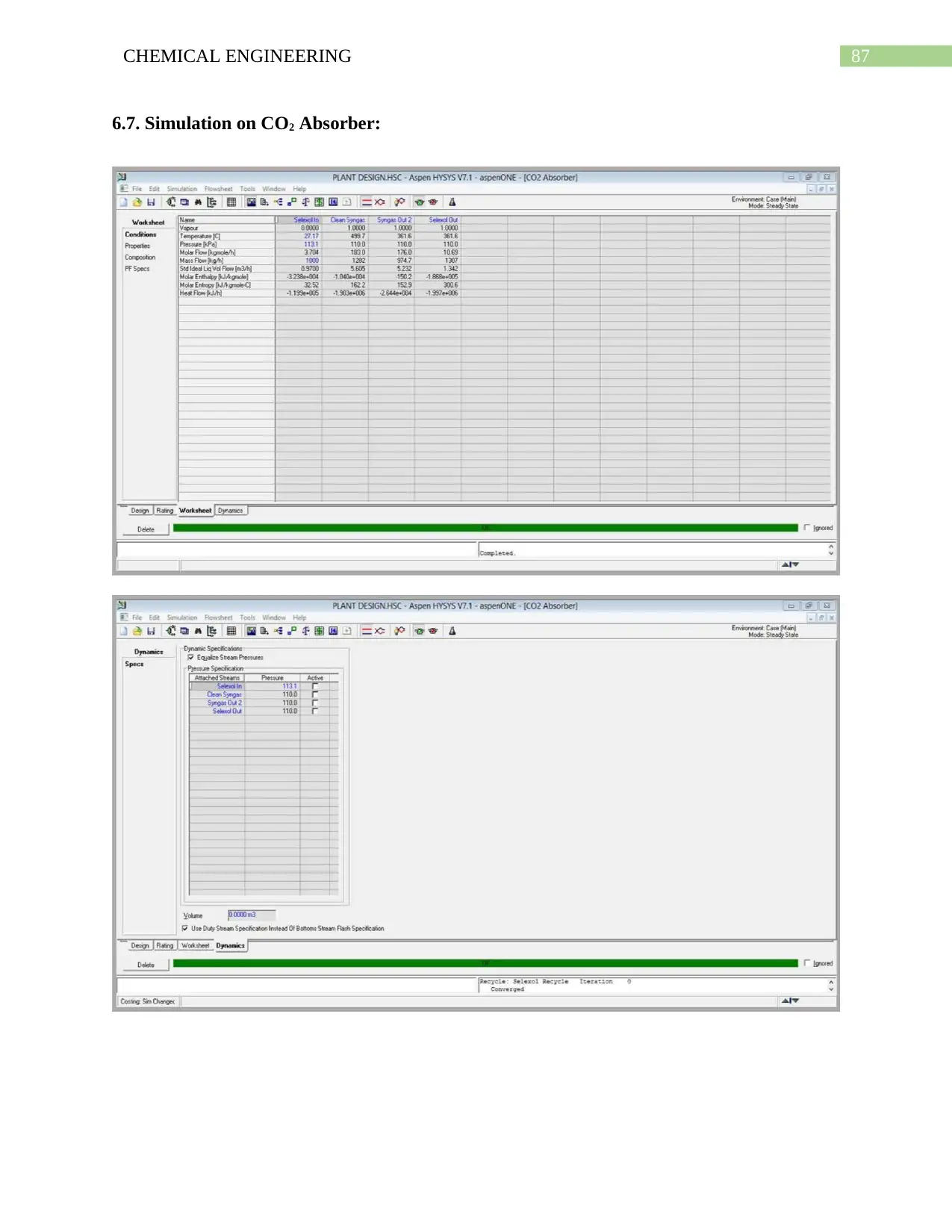
6.7. Simulation on CO2 Absorber:
6.7. Simulation on CO2 Absorber:
88CHEMICAL ENGINEERING
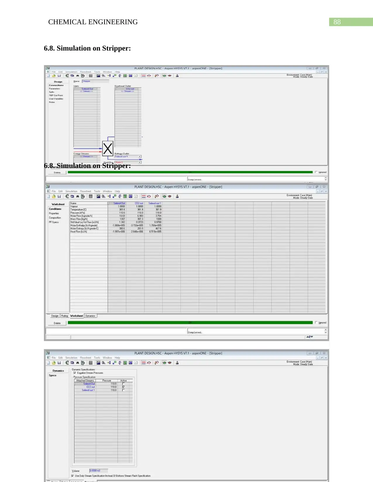
6.8. Simulation on Stripper:
6.8. Simulation on Stripper:
6.8. Simulation on Stripper:
6.8. Simulation on Stripper:
Secure Best Marks with AI Grader
Need help grading? Try our AI Grader for instant feedback on your assignments.
89CHEMICAL ENGINEERING
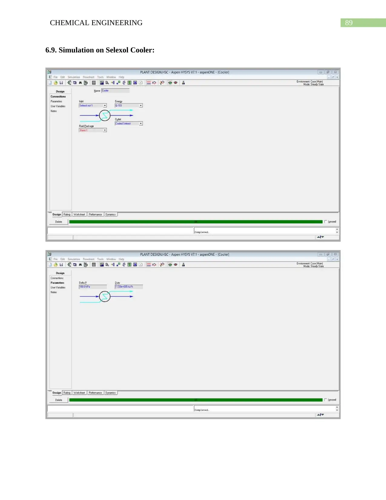
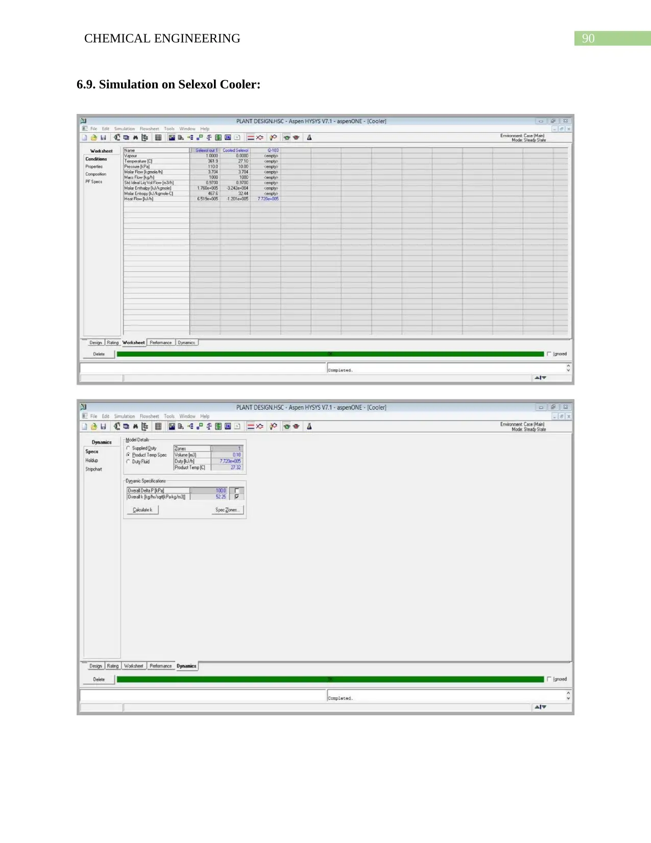
6.9. Simulation on Selexol Cooler:
6.9. Simulation on Selexol Cooler:
90CHEMICAL ENGINEERING
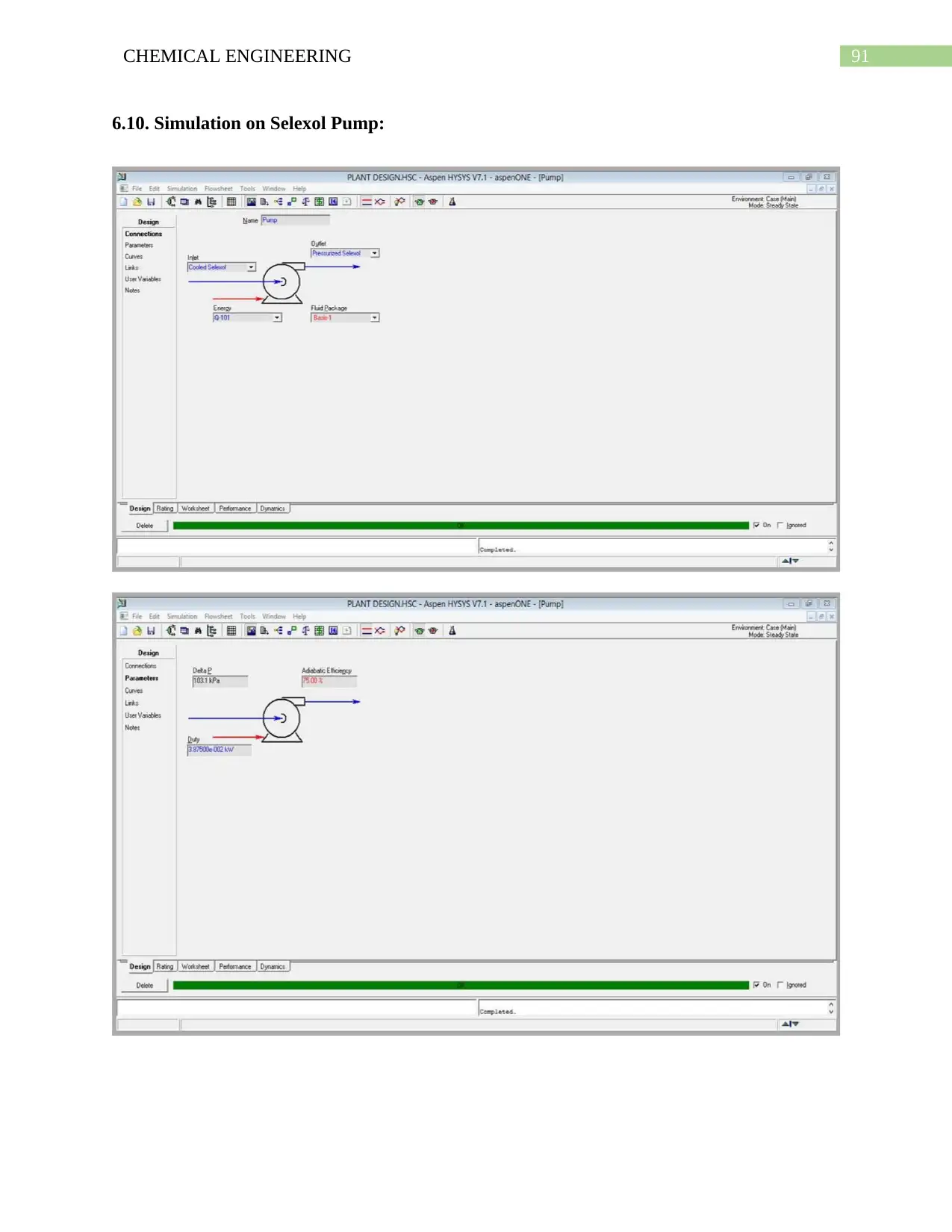
6.9. Simulation on Selexol Cooler:
6.9. Simulation on Selexol Cooler:
91CHEMICAL ENGINEERING
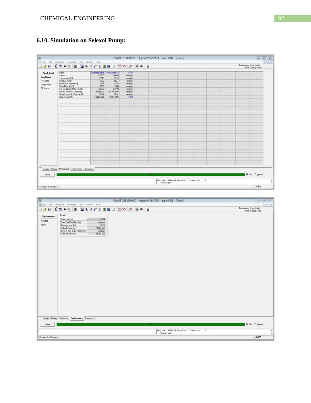
6.10. Simulation on Selexol Pump:
6.10. Simulation on Selexol Pump:
Paraphrase This Document
Need a fresh take? Get an instant paraphrase of this document with our AI Paraphraser
92CHEMICAL ENGINEERING
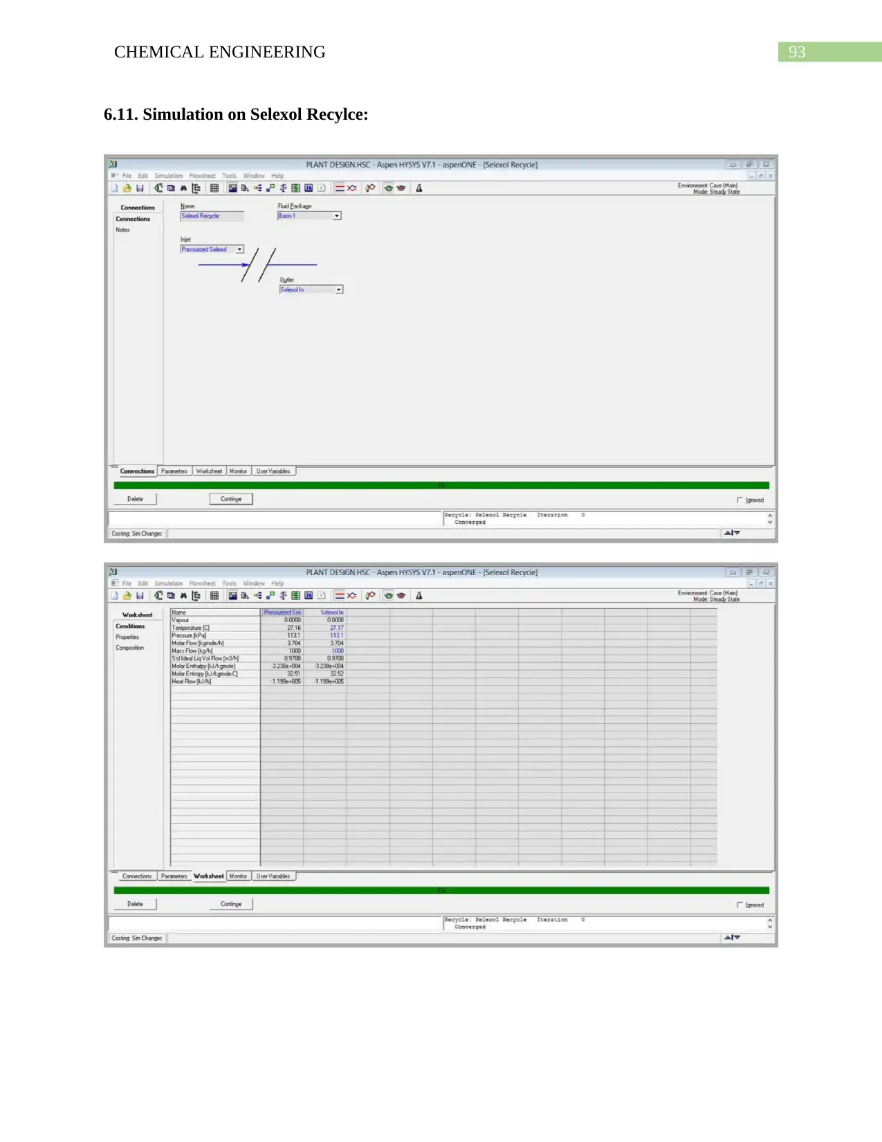
6.10. Simulation on Selexol Pump:
6.10. Simulation on Selexol Pump:
93CHEMICAL ENGINEERING
6.11. Simulation on Selexol Recylce:
6.11. Simulation on Selexol Recylce:
94CHEMICAL ENGINEERING
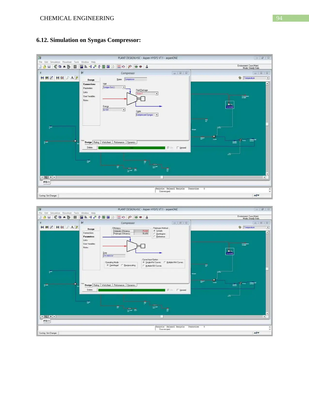
6.12. Simulation on Syngas Compressor:
6.12. Simulation on Syngas Compressor:
Secure Best Marks with AI Grader
Need help grading? Try our AI Grader for instant feedback on your assignments.
95CHEMICAL ENGINEERING
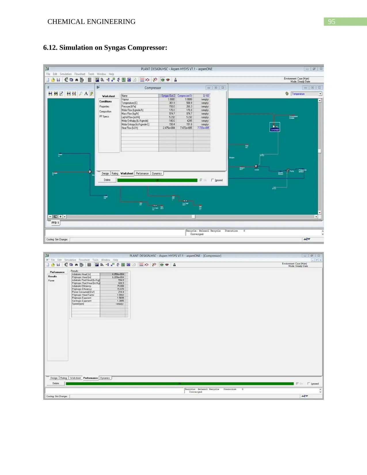
6.12. Simulation on Syngas Compressor:
6.12. Simulation on Syngas Compressor:

96CHEMICAL ENGINEERING
Chapter No.7
Instrumentation
Chapter No.7
Instrumentation
97CHEMICAL ENGINEERING
7.1. Introduction to instrumentation
Instrumentation is generally considered to be process which is applied for the purpose of
monitoring and controlling the major process variables that are generally used during the
operations conducted by the plants. Instruments may be implemented along with the automatic
control loops or might be utilized for the purpose of monitoring in a manual way of the various
process operation. Instruments that are associated with the monitoring of the various critical
process variables would be consisting of an alarms which would be acting in an automatic way
so as to alert the operators in case of any critical and hazardous situations.
7.1.1. Process Control Objectives
The main objectives of the designer includes the following which is generally done while
identifying the instrumentation and control schemes are
For the purpose of detecting the dangerous situations when they develop and for the
purpose of providing alarms and automatic shut-down system.
For the purpose of providing interlocks along with alarms in order to prevent operating
procedures which are dangerous.
For the purpose of maintaining the composition of the product within the quality
standards which are specified.
For the purpose of achieving the desired output of the product.
For the purpose of operating at the lowest production cost, commerce with the other
objectives.
For the purpose of making sure that the process variables are kept within the safe
operating limits which are known.
7.1.2. Elements of control system:
The hardware elements present in almost every control system have been listed below:
Paraphrase This Document
Need a fresh take? Get an instant paraphrase of this document with our AI Paraphraser
98CHEMICAL ENGINEERING
1. Transducers
2. Measuring element or sensors
3. The final control element
4. Controllers
5. Transmission lines
1.The Measuring Element or the Sensors:
This are the instruments which are utilized in order to detect the disturbances, the output
variables which are controlled, or the output variables which are secondary and are necessary
and acts as the main sources of information for the things that are involved in the process.
The choosing of the measuring instrument is totally dependent upon the types of variable that is
to be measured, and along with this it is also essential to record the variables. Below are some of
the typical sensors that is generally used in order to measure the different variables.
1. Level sensors
2. Flow rate sensors
3. Temperature sensors
4. Pressure sensors
Some of the examples of the all this sensors have been listed below.
1. Thermocouples or resistance thermometers used for the making measurements regarding
the temperature.
2. Venturi meters along with the flow nozzles which are used for measuring the flow.
3. Gas chromatograph which is used in order to measure the composition of the stream
The measurement done by a good device is dependent upon the environment in which it
operates. Signal transmission acts as a very important element while selections are made
regarding the measuring device.
99CHEMICAL ENGINEERING
2. Transducers:
It is not possible to use numerous measurements for the purpose of controlling unless and
until conversion of all is not done to physical quantities that mainly includes the electric voltage,
current or a pneumatic signal.
3. Transmission Lines:
Transmission lines are generally used for the purpose of carry the measurements signal to the
controller from the measuring device. Initially it was seen that most of the transmission lines
were pneumatic type which means that this transmission lines are associated with the usage of
the compressed air or liquid for the purpose of transmitting the signal however industrial
automation along with the advancements made in the electronic controllers, electric lines has
been associated with over-ruling the pneumatic transmission lines. It is observed that in most of
the time the measurements that are the results coming from the device is seen to be too much
weak and needs to be amplified in order to get the things right. This makes it very common in
order to find the amplifiers in the transmission lines.
4. Controller:
Controller is considered to be a hardware element which consists of “intelligence”. This is
associated with receiving of the information from the measuring device which is followed by
making of decisions about what type of action must taken. The older versions of the controllers
consisted of intelligence which were limited and were capable of performing simple and limited
operations. However after the usage of digital computers in this field has led to an increased rate
of usage of the complicated control laws.
5. The Final Control Element:
Final control elements are considered to be hardware that are associated with the
implementation of the decisions that the controller has taken.
100CHEMICAL ENGINEERING
7.2. Modes of control:
Various type of modes are used in order to control the operations. The modes are
generally dependent upon the type of controller that is going to be used and also on the actions
that are going to be taken in order to control any process variable. It is better to say that the
actions of the controller depends on the transmitters output signal. Initially comparison of this
signal is done with the set point to the controller and the error that is obtained between these two
is used for the purpose of controlling the process. Different type of controllers are associated
with reacting in a different way so as to control this off-set that occurs between the variable
which are controlled and the set point. Various type of control have bene listed below:
1. Proportional control
2. On-off control
3. Rate or derivative control
4. Composite control
5. Integral control
All this type of actions is generally considered to be the combined control actions of various
kinds of controllers. It is better to say that in various kind of operations, it is a occasional case
that only one control actions is found however more often a composite control action is
practiced. Some of the typical composite control modes that are used commonly have been listed
below.
1. Proportional-Integral-Derivative controller (PID-controller)
2. Integral-Integral controller (PI-controller)
3. Proportional-Derivative controller (PD-controller).
7.3. Characteristics of controller:
The classification of the controllers in a general process has been listed below:
Secure Best Marks with AI Grader
Need help grading? Try our AI Grader for instant feedback on your assignments.
101CHEMICAL ENGINEERING
A. Electronic controllers
B. Hydraulic controllers
C. Pneumatic controllers
7.4. Selection of controller:
The P, PI and PID control modes are usually practiced in the industry. The procedure of
selecting the best type of controller for any of the specific environment is totally systematic.
There exists various ways by which a specific type of system might be controlled by making use
of an appropriate type of controller. Usually the quantitative considerations stemming is used for
selecting the type of controller and this quantitative considerations are obtained after analyzing
the system and ending at the properties of that particular controller and the control objective. The
response of the system is also affected by the Proportional, Integral and Derivative control
modes.
7.4.1. If possible, use a simple proportional controller:
It is possible to use a Simple P-controller in order to achieve acceptable off-set without any
gains of too high values. Usually a simple proportional controller might be used in order to have
gas pressure and liquid level control.
7.4.2. If a simple P-controller is not acceptable, use PI-controller:
There always exists a steady-stat error for proportional controller and for this reason the
systems in which the off-set is to be minimized would be having the incorporation of the PI-
controller. For this reason in flow control applications the PI-controller is found.
7.4.3. Use a PID-controller to increase the speed of the closed loop response and retain
robustness:
The derivative control is having anticipatory characteristic which is responsible for enabling
the usage of somewhat higher values of proportional gains in order to make sure that the off-set
102CHEMICAL ENGINEERING
is minimized associated with lower deviations along with a good response from the system. This
is also associated with adding of stability to the system. For all this reason this type of control is
used in order to sluggish the multi-capacity processes which includes the controlling of the
temperature and composition.
So it can be stated that the best controller is selected depending on the following aspects;
1. Cost
2. Accuracy required
3. Severity of process
7.5. Control loops:
The following control loops are mostly used for the instrumentation and controlling of the
various sections and equipment of plants,.
1. Cascade control loop
2. Feed forward control loop
3. Feedback control loop
4. Ratio control loop
5. Split range control loop
6. Auctioneering control loop
7.5.1. Feedback Control Loop
This is generally considered to be a method of control where comparison between a
measured values of a process variable is done with the desired value of the process variable
along with comparing it with any necessary action which has been taken. Feedback control is
generally considered to be the basic control loops system. The major disadvantage is the
operational procedure.
103CHEMICAL ENGINEERING
7.5.2. Feed Forward Control Loop
“A method of control in which the value of a disturbance is measured, and action is taken to
prevent the disturbance by changing the value of a process variable”
This method of controlled has been designed for the purpose of preventing the occurrence of
errors in a process variable. The major reason due to which the control system is better than
feedback control is that this is associated with it anticipating the changes that occurs in the
process variable before it enters the process takes the preventive action.
7.5.3. Ratio Control
This is considered to be a control loop where the controlling element is associated with
maintaining a predetermined ratio of one variable to another. Basically it can be stated that this is
a control loop which is attached with such a system in which two different streams are associated
with entering a vessel for reaction which might be of any kind. For the purpose of maintaining
the stoichiometric quantities of different streams this type of loop is used in order to make sure
that proper process is going on in the process vessel.
7.5.4. Auctioneering Control Loop
The major use of this type control loop is seen in huge vessel in which the readings of a
single variable might be varying according to various locations. Additionally this type of control
loop is associated with ensuring safe operation due to the reason that it employs all the readings
of different locations in a simultaneous way, which is followed by comparing them with the set
point, in case when any of those readings is seen to be deviating from the set point then the
controller would be associated with sending of appropriate signal to the final control element.
7.5.5. Split Range Loops
This is the loop controller in which per set is consisting of different values with respect to
different action that are to be taken at various conditions. The major advantage of using this loop
Paraphrase This Document
Need a fresh take? Get an instant paraphrase of this document with our AI Paraphraser
104CHEMICAL ENGINEERING
is that it is associated with proper conditions which helps in avoiding of the abnormalities at
differential levels.
7.5.6. Cascade Control Loop
In this type of control it is seen that two or more than two control loops are arranged in such
a way that the output of, one of the controlling element would be associated with setting the
another controlling elements point. The major use of this control loop is seen in places where
proper and quick control is difficult by application of simple feed forward or feed backward
control.
7.6. Control loop for Gasifier Reactor:
The controlling of the temperature inside a gasifier reactor is very important. The major
reason lying behind this control is that, with increase in temperature of the gasifier might lead to
a situation where the desired reaction cannot be obtained. For this reason the usage of the
temperature control in the gasifier can be very helpful in order to solve this problem .the
controlling of the temperature in the gasifier is done by the steam which enters the gasifier.
105CHEMICAL ENGINEERING
7.7. Control loop for Heat Exchanger:
Heat Exchangers is generally considered to be inherently stable operating units. But it is
necessary that there exist control over the flow parameters which is necessary along with which
there should exist proper indication and recording of the inlet and outlet conditions.
Presence of the Thermocouples in the protective thermal well which would be acting as
temperature measuring elements. Besides this it is essential to take particular care so as to
minimize the effect of air gap that exist between the thermocouple and thermal well which is to
be done by proper installation of conducting sleeves.
106CHEMICAL ENGINEERING
7.8. Control loop for Compressor:
Compressor is generally used for the purpose of obtaining the pressure that is required
for the absorption column in order to make sure that pressure controller is used for the
purpose of checking the pressure of the stream.
7.8. Control loop for Compressor:
Compressor is generally used for the purpose of obtaining the pressure that is required
for the absorption column in order to make sure that pressure controller is used for the
purpose of checking the pressure of the stream.
Secure Best Marks with AI Grader
Need help grading? Try our AI Grader for instant feedback on your assignments.
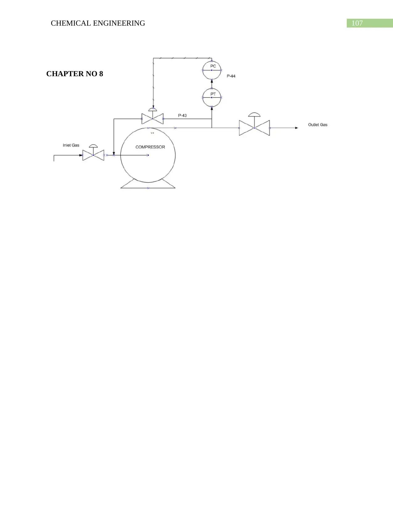
107CHEMICAL ENGINEERING
CHAPTER NO 8
CHAPTER NO 8
108CHEMICAL ENGINEERING
8.1. Introduction:
Various kind of chemical engineering design projects have been conducted in order to
provide information and this makes it possible to estimate the entire cost as well as the cost
required for the various operations. Chemical plants are also built for the purpose of making a
profit and also for the purpose of estimating the investment that is required and the cost for the
production is to be done before accessing the profitability of the project. Cost Estimation is
generally considered to be a subject which is specialized and a profession however the design
engineer must have the capability of making rough cost estimation to decide between the project
alternatives and also for the purpose of optimizing the design.
8.2. Costs, Revenues, Profits:
The components of project costs and revenues have been introduced in this section.
8.2.1. Fixed Capital Investment:
This is generally considered to be the over-all cost required for designing, constructing
and installing a plant. This is also associated with making of modifications that is needed in
order to prepare a plant site. The fixed capital investment is made up of:
1. Needed modifications and improvements in the site infra-structure which is also known
as off-site or OSBL investment.
2. The Inside Battery Limits (ISBL) investment – this is the cost of the plant itself.
3. Contingency charges.
4. Engineering and construction costs.
8.2.1.1. ISBL Plant Cost:
This mainly includes the cost that is need in order to procure and install each and every
process equipment.
109CHEMICAL ENGINEERING
Direct field costs mainly include the following:
1. main process equipment, which includes the vessels, furnaces, , reactors, heat
exchangers, pumps, coolers, fans, turbines, motors, columns, centrifuge, driers, filters,
and many more., including field fabrication and testing if necessary.
2. Installation labor and supervision.
3. Civil works which mainly includes the roads, foundations, piling, buildings, sewers,
ditches, bunds and many more.
4. Bulk items, which includes the piping, valves, wiring, instruments, structures, insulation,
paint, lube oils, solvents, catalysts, etc.
In addition to the direct field costs there will be indirect field costs as follows,
1. Field expenses and services which includes the field canteens, specialist costs, overtime
pay and adverse weather costs workshops etc.
2. Cost of Construction which includes the construction equipment rental, temporary
construction, temporary water and power, construction.
3. Construction insurance.
4. Benefits and burdens of Labor.
8.2.1.2. Off-site Costs:
OSBL investment mainly includes the costs of the additions which are essentially to be
made to the site infra-structure for the purpose of accommodating the addition of a new plant or
increasing the capacity of an existing plant. Off-site investment may include:
1. Power generation plants, turbines engines, standby generators.
2. Electric main substations, transformers, switchgears and power lines.
3. Water pipes, water demineralization, waste water treatment plants.
4. Boilers, steam mains, condensate lines, BFW treatment plant, supply pumps.
Paraphrase This Document
Need a fresh take? Get an instant paraphrase of this document with our AI Paraphraser
110CHEMICAL ENGINEERING
5. Cooling towers, circulation pumps, cooling water mains and treatment.
6. Air separation plants to provide site N2 for inert gases, nitrogen lines.
7. Pipe bridges, feed and product pipelines.
8. Driers and blowers for instrument air, instrument air lines.
9. Workshop and maintenance facilities.
10. Tanker farms, loading facilities, conveyors, docks, ware houses, railroads.
11. Laboratories, analytical equipment, offices, canteens, changing rooms, CCR.
12. Site security, fencing, gate houses, landscaping.
13. Emergency services, fire fight equipment, fire hydrants, medical facilities
8.2.1.3. Engineering Costs:
This type of cost is also referred to as home office costs or contractor charge, which
mainly includes the costs of detailed design and other engineering services that are required to
carry out the project:
1. Contractor`s profit
2. Bonding
3. Procurement of main plant items and bulks.
4. Construction supervision and services.
5. Detailed design engineering of process equipment, piping systems, control systems and
off-sites, plant layout, drafting, cost engineering, scale modules and civil engineering.
8.2.1.4. Contingency Charges:
This are the extra costs which are added into the project budget for the purpose of
allowing the variation from the cost estimated.
1. Changes in project scope
2. Currency fluctuations
111CHEMICAL ENGINEERING
3. Labor disputes
4. Changes in prices
5. Subcontractor problems
1. Other unexpected problems.
8.3. Working Capital:
This is generally the extra money that is required, working capital mainly includes:
1. Cash on hand – estimated as 1 week cost of production.
2. Spare parts inventory – estimated as 1-2% of ISBL plus OSBL investment cost.
3. Value of product and by product inventory - estimated as 2 weeks cost of production.
4. Value of raw materials inventory, usually estimated as 2 weeks delivered cost of raw
materials.
5. Credit for accounts payable – feed stocks, solvents, catalysts, packaging etc. received but
not paid yet for – estimated as 1 month delivered cost.
6. Accounts receivable – production shipped but not yet paid for – estimated as 1 month
cost of production.
8.4. Variable Costs of Production:
These costs are the costs that are proportional to the plant output or operation rate.
These include the costs of:
1. Consumables – solvents, acids, bases, inert materials, corrosion inhibitors, additives,
catalysts and many more.
2. Utilities fuels that are utilized by the process heaters, steam, cooling water, electricity,
raw water, instrument air, nitrogen etc.
112CHEMICAL ENGINEERING
3. Packaging and shipping related cots that includes the– drums, bags, tankers, freight
charges and many more.
4. Effluent disposal.
5. Raw materials that are used during the process.
8.5. Fixed Costs of Production:
The costs that are incurred and are irrespective of the operations of the plant. If plant cuts
back its production, these costs are not reduced. Fixed costs mainly include the following:
1. Supervision – usually taken as 25% of operating labor
2. Rent of land – typically 1-2% of ISBL plus OSBL investment.
3. Operating labor
4. Direct salary overhead – (40-60% of operating labor + supervision).
5. General plant overhead – 65% of total labor (including supervision and direct overhead)
plus maintenance.
6. Sales and marketing costs.
7. Allocated environmental charges – typically 1% of ISBL and OSBL cost.
8. Property taxes and insurance – typically 1-2% of ISBL fixed capital.
9. Maintenance, which includes both materials and labor, and it typically estimated as 3-5%
of ISBL investment, depending on the expected plant reliability.
10. Capital charges
11. Running the license fees and royalty payments
8.6. Estimation of Equipment Cost:
8.6.1 Dryer:
Type = Rotary Dryer Indirect Gas Fired
Secure Best Marks with AI Grader
Need help grading? Try our AI Grader for instant feedback on your assignments.
113CHEMICAL ENGINEERING
Area = 6 m2
Purchase cost = $28700
This is cost of year 2007.
The average increase in the cost is about 2.5% per year.
Using this value we predict the heat exchanger purchased cost in year 2013
In year 2013;
Purchased cost = 28700 × (1.025)6
Purchased cost = $33283.3
8.6.2. Gasifier
Length of gasifier = 5.94 m
Diameter of gasifier = 1.32 m
Material of construction for tubes and shell = carbon steel
Type = Plug flow
Pressure = 40 bar
Pressure factor = 1.6
Type factor = 1.0
Bare cost = $18000
Purchased cost = bare cost × pressure factor × type factor
= 18000 × 1.6 × 1
Purchased cost = 28800$
114CHEMICAL ENGINEERING
This is the cost in year 2004
The average increase in the cost is about 2.5% per year [1]
Using this value we predict the heat exchanger purchased cost in year 2013
In year 2013;
Purchased cost = 28800 × (1.025)9
Purchased cost = $35967
8.6.3. Heat Exchanger:
Heat transfer area = A= 50.27m2
Material of construction for tubes and shell = carbon steel
Type = floating head
Pressure = 1 bar
Pressure factor = 1.0
Type factor = 1.0
Bare cost = $22000
Purchased cost = bare cost × pressure factor × type factor
= 22000 × 1 × 1
Purchased cost = 22000$
This is the cost in year 2004
The average increase in the cost is about 2.5% per year [1]
Using this value we predict the heat exchanger purchased cost in year 2013
This is the cost in year 2004
The average increase in the cost is about 2.5% per year [1]
Using this value we predict the heat exchanger purchased cost in year 2013
In year 2013;
Purchased cost = 28800 × (1.025)9
Purchased cost = $35967
8.6.3. Heat Exchanger:
Heat transfer area = A= 50.27m2
Material of construction for tubes and shell = carbon steel
Type = floating head
Pressure = 1 bar
Pressure factor = 1.0
Type factor = 1.0
Bare cost = $22000
Purchased cost = bare cost × pressure factor × type factor
= 22000 × 1 × 1
Purchased cost = 22000$
This is the cost in year 2004
The average increase in the cost is about 2.5% per year [1]
Using this value we predict the heat exchanger purchased cost in year 2013
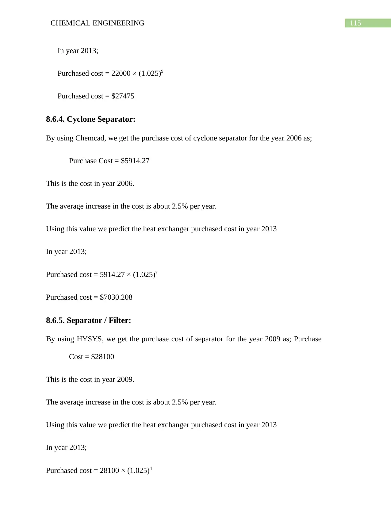
115CHEMICAL ENGINEERING
In year 2013;
Purchased cost = 22000 × (1.025)9
Purchased cost = $27475
8.6.4. Cyclone Separator:
By using Chemcad, we get the purchase cost of cyclone separator for the year 2006 as;
Purchase Cost = $5914.27
This is the cost in year 2006.
The average increase in the cost is about 2.5% per year.
Using this value we predict the heat exchanger purchased cost in year 2013
In year 2013;
Purchased cost = 5914.27 × (1.025)7
Purchased cost = $7030.208
8.6.5. Separator / Filter:
By using HYSYS, we get the purchase cost of separator for the year 2009 as; Purchase
Cost = $28100
This is the cost in year 2009.
The average increase in the cost is about 2.5% per year.
Using this value we predict the heat exchanger purchased cost in year 2013
In year 2013;
Purchased cost = 28100 × (1.025)4
In year 2013;
Purchased cost = 22000 × (1.025)9
Purchased cost = $27475
8.6.4. Cyclone Separator:
By using Chemcad, we get the purchase cost of cyclone separator for the year 2006 as;
Purchase Cost = $5914.27
This is the cost in year 2006.
The average increase in the cost is about 2.5% per year.
Using this value we predict the heat exchanger purchased cost in year 2013
In year 2013;
Purchased cost = 5914.27 × (1.025)7
Purchased cost = $7030.208
8.6.5. Separator / Filter:
By using HYSYS, we get the purchase cost of separator for the year 2009 as; Purchase
Cost = $28100
This is the cost in year 2009.
The average increase in the cost is about 2.5% per year.
Using this value we predict the heat exchanger purchased cost in year 2013
In year 2013;
Purchased cost = 28100 × (1.025)4
Paraphrase This Document
Need a fresh take? Get an instant paraphrase of this document with our AI Paraphraser
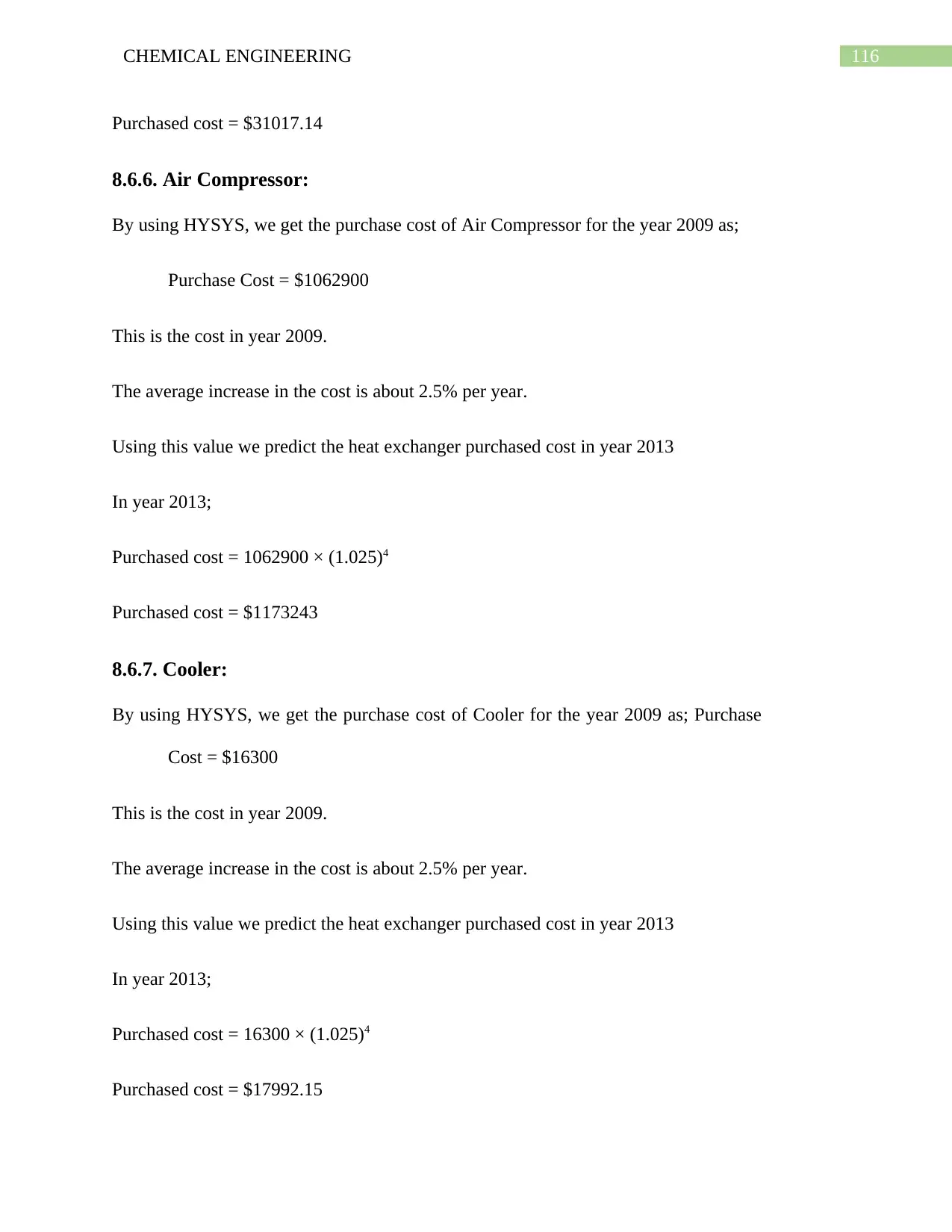
116CHEMICAL ENGINEERING
Purchased cost = $31017.14
8.6.6. Air Compressor:
By using HYSYS, we get the purchase cost of Air Compressor for the year 2009 as;
Purchase Cost = $1062900
This is the cost in year 2009.
The average increase in the cost is about 2.5% per year.
Using this value we predict the heat exchanger purchased cost in year 2013
In year 2013;
Purchased cost = 1062900 × (1.025)4
Purchased cost = $1173243
8.6.7. Cooler:
By using HYSYS, we get the purchase cost of Cooler for the year 2009 as; Purchase
Cost = $16300
This is the cost in year 2009.
The average increase in the cost is about 2.5% per year.
Using this value we predict the heat exchanger purchased cost in year 2013
In year 2013;
Purchased cost = 16300 × (1.025)4
Purchased cost = $17992.15
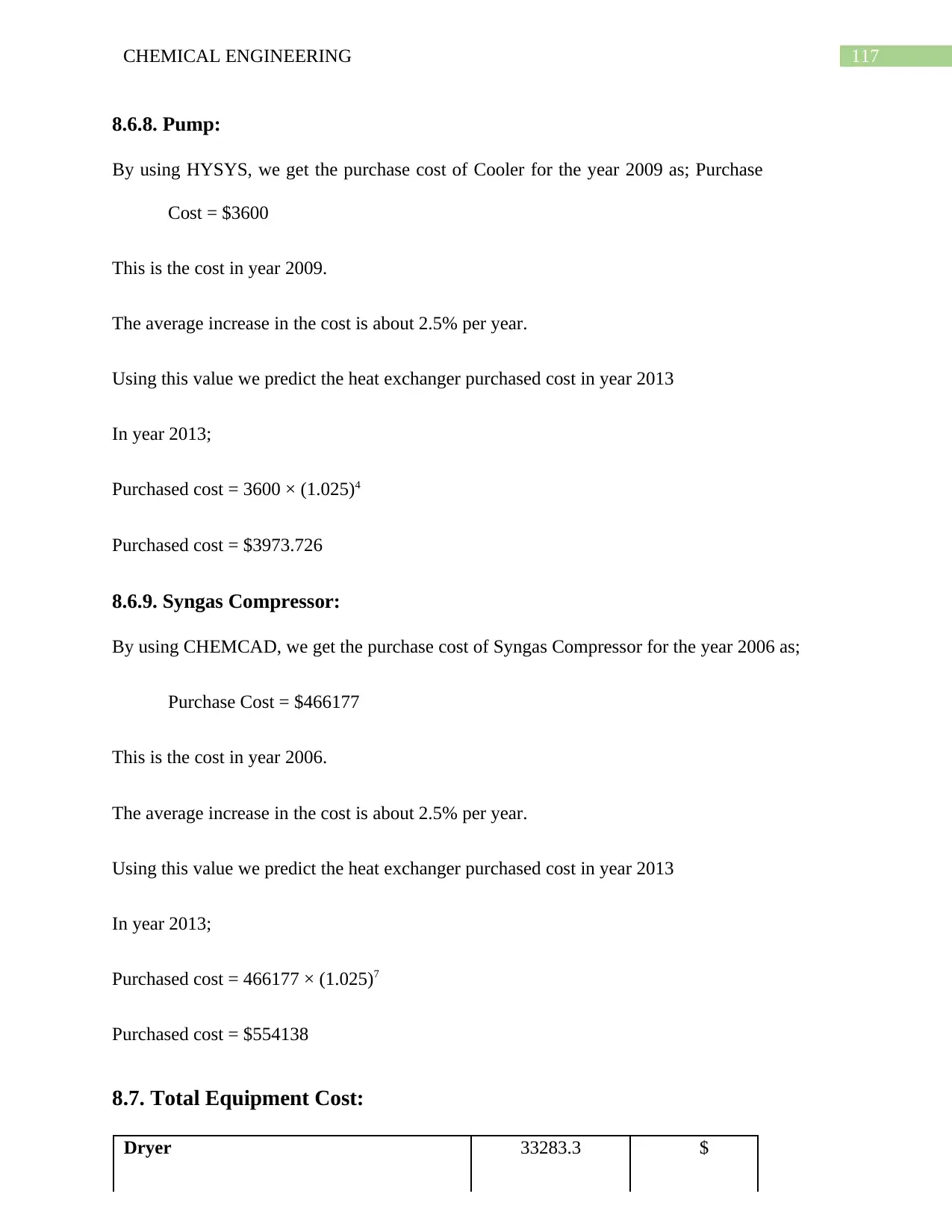
117CHEMICAL ENGINEERING
8.6.8. Pump:
By using HYSYS, we get the purchase cost of Cooler for the year 2009 as; Purchase
Cost = $3600
This is the cost in year 2009.
The average increase in the cost is about 2.5% per year.
Using this value we predict the heat exchanger purchased cost in year 2013
In year 2013;
Purchased cost = 3600 × (1.025)4
Purchased cost = $3973.726
8.6.9. Syngas Compressor:
By using CHEMCAD, we get the purchase cost of Syngas Compressor for the year 2006 as;
Purchase Cost = $466177
This is the cost in year 2006.
The average increase in the cost is about 2.5% per year.
Using this value we predict the heat exchanger purchased cost in year 2013
In year 2013;
Purchased cost = 466177 × (1.025)7
Purchased cost = $554138
8.7. Total Equipment Cost:
Dryer 33283.3 $
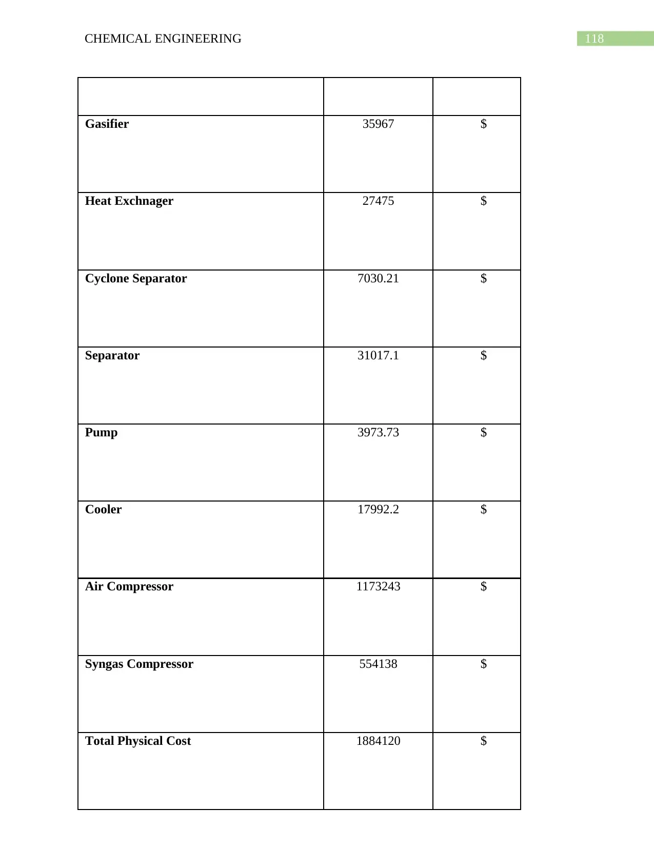
118CHEMICAL ENGINEERING
Gasifier 35967 $
Heat Exchnager 27475 $
Cyclone Separator 7030.21 $
Separator 31017.1 $
Pump 3973.73 $
Cooler 17992.2 $
Air Compressor 1173243 $
Syngas Compressor 554138 $
Total Physical Cost 1884120 $
Gasifier 35967 $
Heat Exchnager 27475 $
Cyclone Separator 7030.21 $
Separator 31017.1 $
Pump 3973.73 $
Cooler 17992.2 $
Air Compressor 1173243 $
Syngas Compressor 554138 $
Total Physical Cost 1884120 $
Secure Best Marks with AI Grader
Need help grading? Try our AI Grader for instant feedback on your assignments.
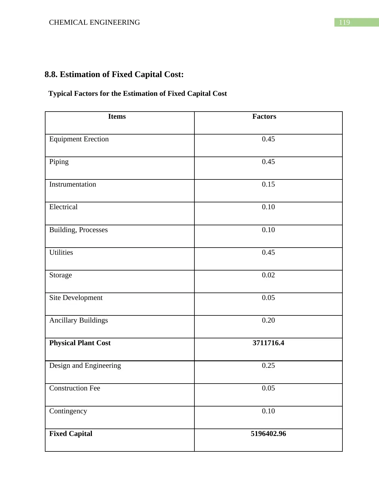
119CHEMICAL ENGINEERING
8.8. Estimation of Fixed Capital Cost:
Typical Factors for the Estimation of Fixed Capital Cost
Items Factors
Equipment Erection 0.45
Piping 0.45
Instrumentation 0.15
Electrical 0.10
Building, Processes 0.10
Utilities 0.45
Storage 0.02
Site Development 0.05
Ancillary Buildings 0.20
Physical Plant Cost 3711716.4
Design and Engineering 0.25
Construction Fee 0.05
Contingency 0.10
Fixed Capital 5196402.96
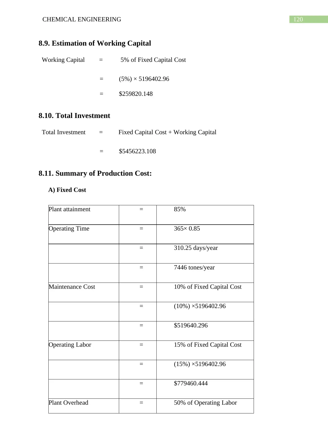
120CHEMICAL ENGINEERING
8.9. Estimation of Working Capital
Working Capital = 5% of Fixed Capital Cost
= (5%) × 5196402.96
= $259820.148
8.10. Total Investment
Total Investment = Fixed Capital Cost + Working Capital
= $5456223.108
8.11. Summary of Production Cost:
A) Fixed Cost
Plant attainment = 85%
Operating Time = 365× 0.85
= 310.25 days/year
= 7446 tones/year
Maintenance Cost = 10% of Fixed Capital Cost
= (10%) ×5196402.96
= $519640.296
Operating Labor = 15% of Fixed Capital Cost
= (15%) ×5196402.96
= $779460.444
Plant Overhead = 50% of Operating Labor
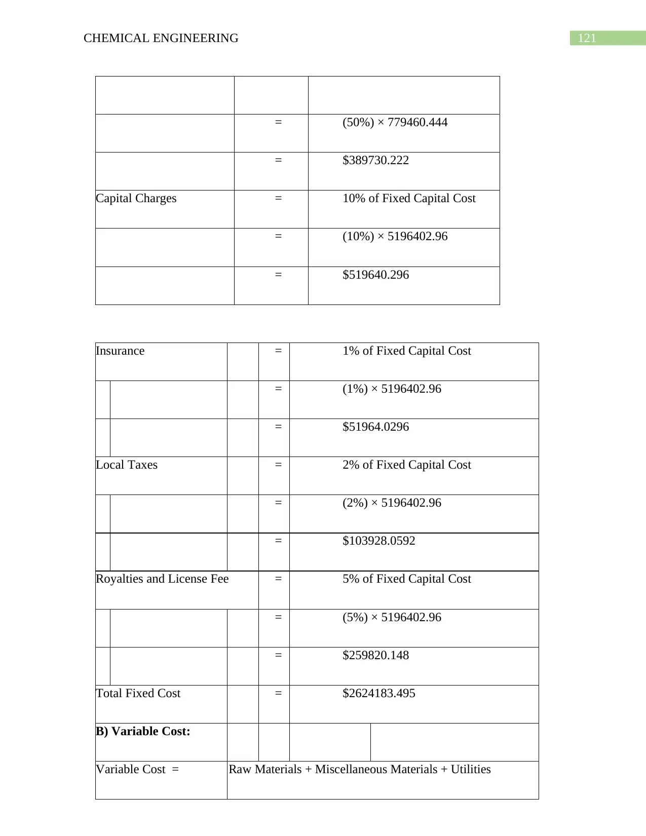
121CHEMICAL ENGINEERING
= (50%) × 779460.444
= $389730.222
Capital Charges = 10% of Fixed Capital Cost
= (10%) × 5196402.96
= $519640.296
Insurance = 1% of Fixed Capital Cost
= (1%) × 5196402.96
= $51964.0296
Local Taxes = 2% of Fixed Capital Cost
= (2%) × 5196402.96
= $103928.0592
Royalties and License Fee = 5% of Fixed Capital Cost
= (5%) × 5196402.96
= $259820.148
Total Fixed Cost = $2624183.495
B) Variable Cost:
Variable Cost = Raw Materials + Miscellaneous Materials + Utilities
Paraphrase This Document
Need a fresh take? Get an instant paraphrase of this document with our AI Paraphraser
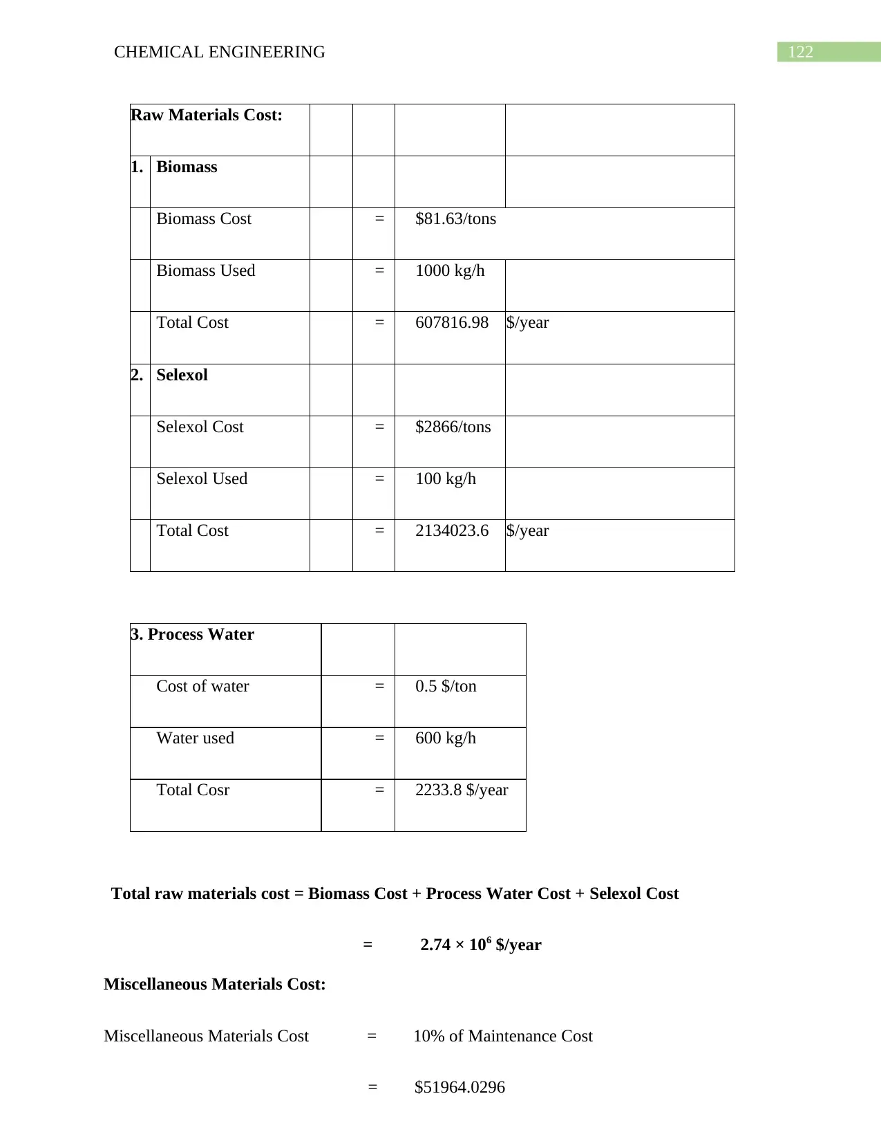
122CHEMICAL ENGINEERING
Raw Materials Cost:
1. Biomass
Biomass Cost = $81.63/tons
Biomass Used = 1000 kg/h
Total Cost = 607816.98 $/year
2. Selexol
Selexol Cost = $2866/tons
Selexol Used = 100 kg/h
Total Cost = 2134023.6 $/year
3. Process Water
Cost of water = 0.5 $/ton
Water used = 600 kg/h
Total Cosr = 2233.8 $/year
Total raw materials cost = Biomass Cost + Process Water Cost + Selexol Cost
= 2.74 × 10⁶ $/year
Miscellaneous Materials Cost:
Miscellaneous Materials Cost = 10% of Maintenance Cost
= $51964.0296
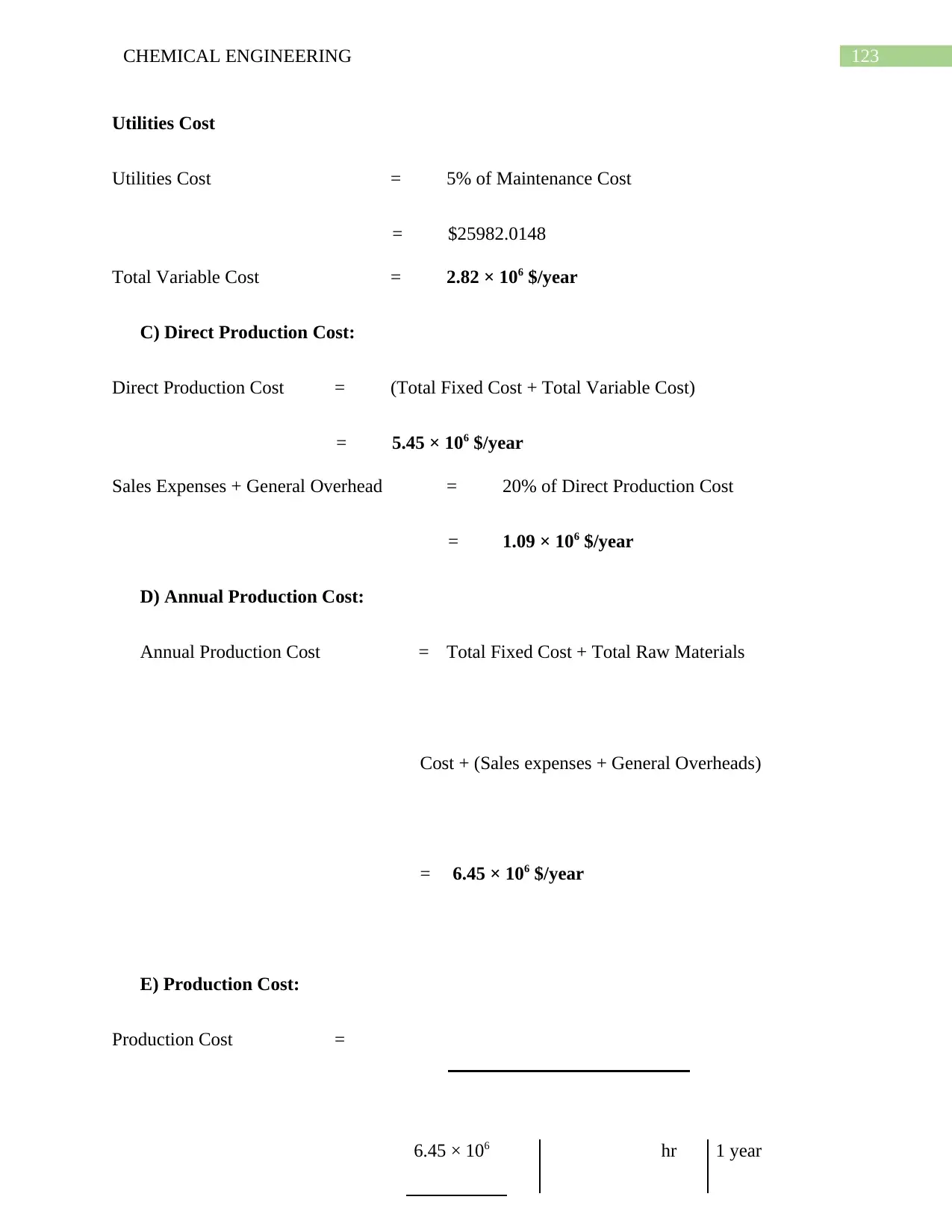
123CHEMICAL ENGINEERING
Utilities Cost
Utilities Cost = 5% of Maintenance Cost
= $25982.0148
Total Variable Cost = 2.82 × 10⁶ $/year
C) Direct Production Cost:
Direct Production Cost = (Total Fixed Cost + Total Variable Cost)
= 5.45 × 10⁶ $/year
Sales Expenses + General Overhead = 20% of Direct Production Cost
= 1.09 × 10⁶ $/year
D) Annual Production Cost:
Annual Production Cost = Total Fixed Cost + Total Raw Materials
Cost + (Sales expenses + General Overheads)
= 6.45 × 10⁶ $/year
E) Production Cost:
Production Cost =
6.45 × 10⁶ hr 1 year
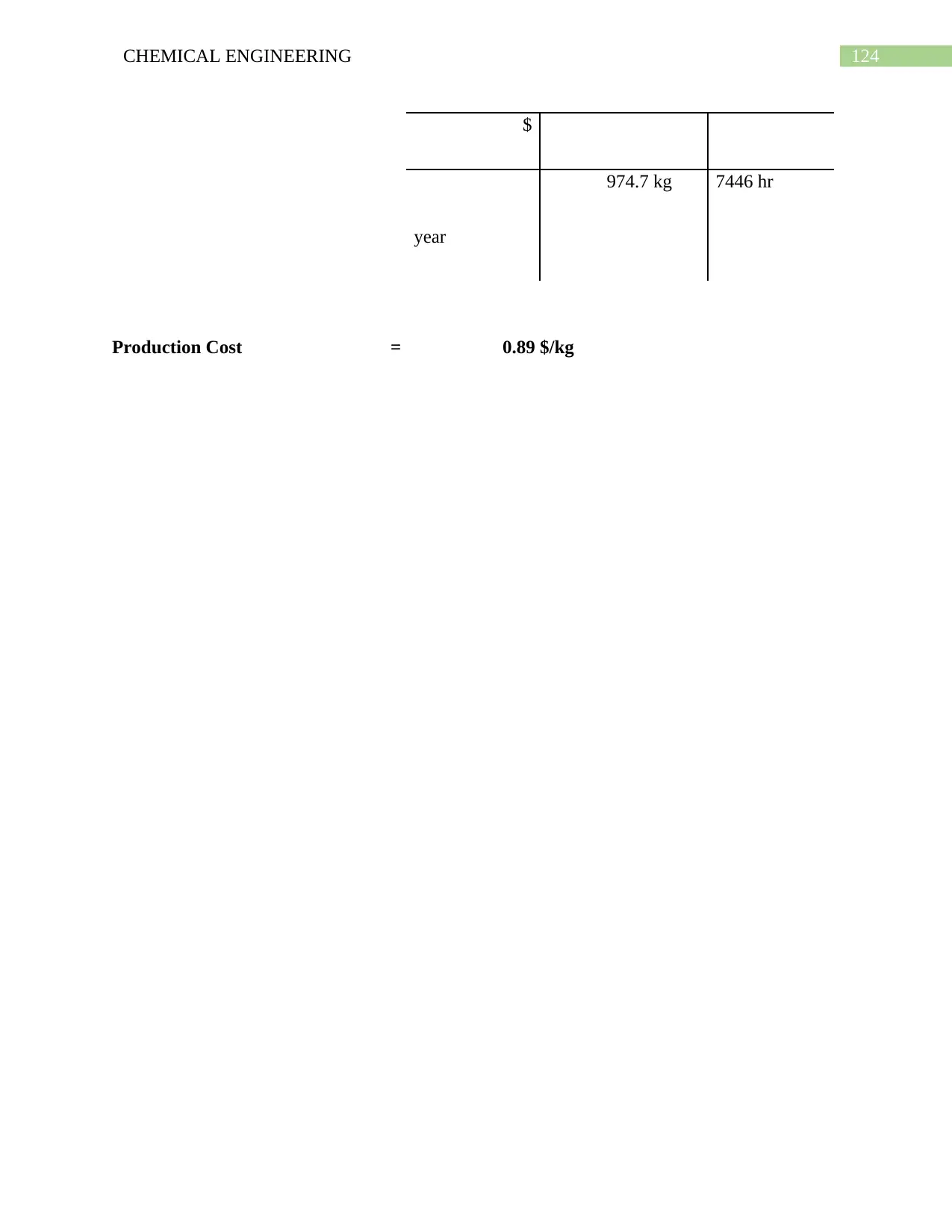
124CHEMICAL ENGINEERING
$
974.7 kg 7446 hr
year
Production Cost = 0.89 $/kg
$
974.7 kg 7446 hr
year
Production Cost = 0.89 $/kg
Secure Best Marks with AI Grader
Need help grading? Try our AI Grader for instant feedback on your assignments.
125CHEMICAL ENGINEERING
References:
Books:
1. David M. Himmelblau, “Basic Principles and Calculations in Chemical Engineering”,
6th Edition, Prentice Hall PTR, 1996.
2. Coulson, J.M., and Richardson, J.F., “Chemical Engineering”, 4th Edition, Volume 6,
Butterworth Heminann, 1991.
3. D. Q. Kern, “Process Heat Transfer”, Mc-Graw Hill, 2000.
4. Levenspiel, O., “Chemical Reaction Engineering”, 3rd Edition, John Wiley and Sons
Inc., 1999.
5. Coulson, J.M., and Richardson, J.F., “Chemical Engineering”, 4th Edition, Volume 1,
Butterworth Heminann, 1991.
6. Coulson, J.M., and Richardson, J.F., “Chemical Engineering”, 4th Edition, Volume 2,
Butterworth Heminann, 1991.
7. Mc-Cabe, W.L., Smith, J.C., & Harriot, P., “Unit Operations of Chemical
Engineering”, 5th Edition, Mc-Graw Hill, Inc., 1993.
8. J. M. Smith, “Introduction to Chemical Engineering Thermodynamics”, 6th Edition,
Mc-Graw Hill.
9. Perry, R.H and D.W.Green, “Perry`s Chemical Engineering Handbook”, 7th Edition,
Mc-Graw Hill New York, 1997.
14
4

126CHEMICAL ENGINEERING
10. George Stephanopoulos, “Chemical Process Control”.
11. Carlos A.Smith, Armando B. Corripio, “Principles and Practice of
Automatic Process Control”.
10. George Stephanopoulos, “Chemical Process Control”.
11. Carlos A.Smith, Armando B. Corripio, “Principles and Practice of
Automatic Process Control”.

127CHEMICAL ENGINEERING
1 out of 127
Related Documents
Your All-in-One AI-Powered Toolkit for Academic Success.
+13062052269
info@desklib.com
Available 24*7 on WhatsApp / Email
![[object Object]](/_next/static/media/star-bottom.7253800d.svg)
Unlock your academic potential
© 2024 | Zucol Services PVT LTD | All rights reserved.


