Energy Storage: Pumped Hydro-Power and Flywheel Energy Storage
VerifiedAdded on 2023/06/15
|45
|7041
|411
AI Summary
This article discusses the principles, mechanical design, materials, and construction of pumped hydro-power and flywheel energy storage. It also covers their applications, where they are currently operational, and their design. Additionally, it provides insights into the operation of flywheel energy storage and how it stores energy in the form of kinetic energy.
Contribute Materials
Your contribution can guide someone’s learning journey. Share your
documents today.
Energy Storage 1
ENERGY STORAGE
By Name
Course
Instructor
Institution
Location
Date
Contents
ENERGY STORAGE
By Name
Course
Instructor
Institution
Location
Date
Contents
Secure Best Marks with AI Grader
Need help grading? Try our AI Grader for instant feedback on your assignments.
Energy Storage 2
PUMPED HYDRO-POWER ENERGY.......................................................................................................2
PRINCIPLE OPERATION OF THE PUMPED HYDRO....................................................................................2
MECHANICAL DESIGN FEATURE MATERIALS AND CONSTRUCTION......................................................6
1. Forebay and intake structure...........................................................................................................6
2. Head Race........................................................................................................................................7
3. Surge Tank.......................................................................................................................................7
4. Turbines...........................................................................................................................................8
5. Tail Race( Draft Tube ).....................................................................................................................8
Construction of the pumped hydro energy...........................................................................................9
Application and where currently operational.....................................................................................10
Design....................................................................................................................................................10
Summary.............................................................................................................................................12
FLYWHEEL ENERGY STORAGE.............................................................................................................13
OPERATION............................................................................................................................................13
MATERIALS USED IN DESIGN.................................................................................................................15
Energy Storage 3
CONSTRUCTION OF FLYWHEEL..............................................................................................................15
WHERE THIS IS EMPLOYED....................................................................................................................16
DESIGN..................................................................................................................................................16
REAL VIEW OF FLYWHEEL......................................................................................................................19
SUMMARY.............................................................................................................................................19
Energy Storage 4
Question 1
PUMPED HYDRO-POWER ENERGY
PRINCIPLE OPERATION OF THE PUMPED HYDRO
The water moving via the turbine is stored in a `` tail race pond`` for the period of low load. The
water is then pumped back to the head reservoir by the aid of the extra energy present. The water
pumped back can then be employed again in the production of electrical energy during the periods of
peak load (McMurry, 2015).
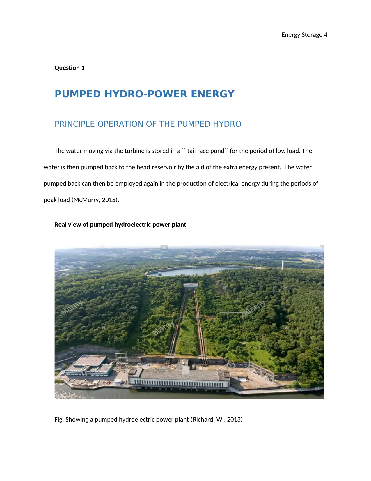
Real view of pumped hydroelectric power plant
Fig: Showing a pumped hydroelectric power plant (Richard, W., 2013)
Secure Best Marks with AI Grader
Need help grading? Try our AI Grader for instant feedback on your assignments.
Energy Storage 5
Fig: showing a real view for pumped hydro power energy
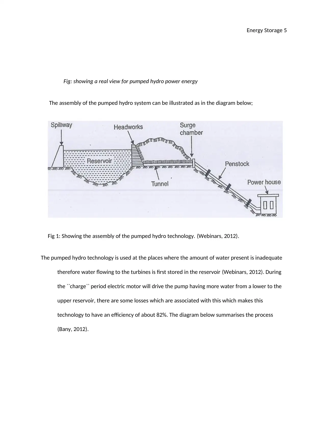
The assembly of the pumped hydro system can be illustrated as in the diagram below;
Fig 1: Showing the assembly of the pumped hydro technology. (Webinars, 2012).
The pumped hydro technology is used at the places where the amount of water present is inadequate
therefore water flowing to the turbines is first stored in the reservoir (Webinars, 2012). During
the ``charge`` period electric motor will drive the pump having more water from a lower to the
upper reservoir, there are some losses which are associated with this which makes this
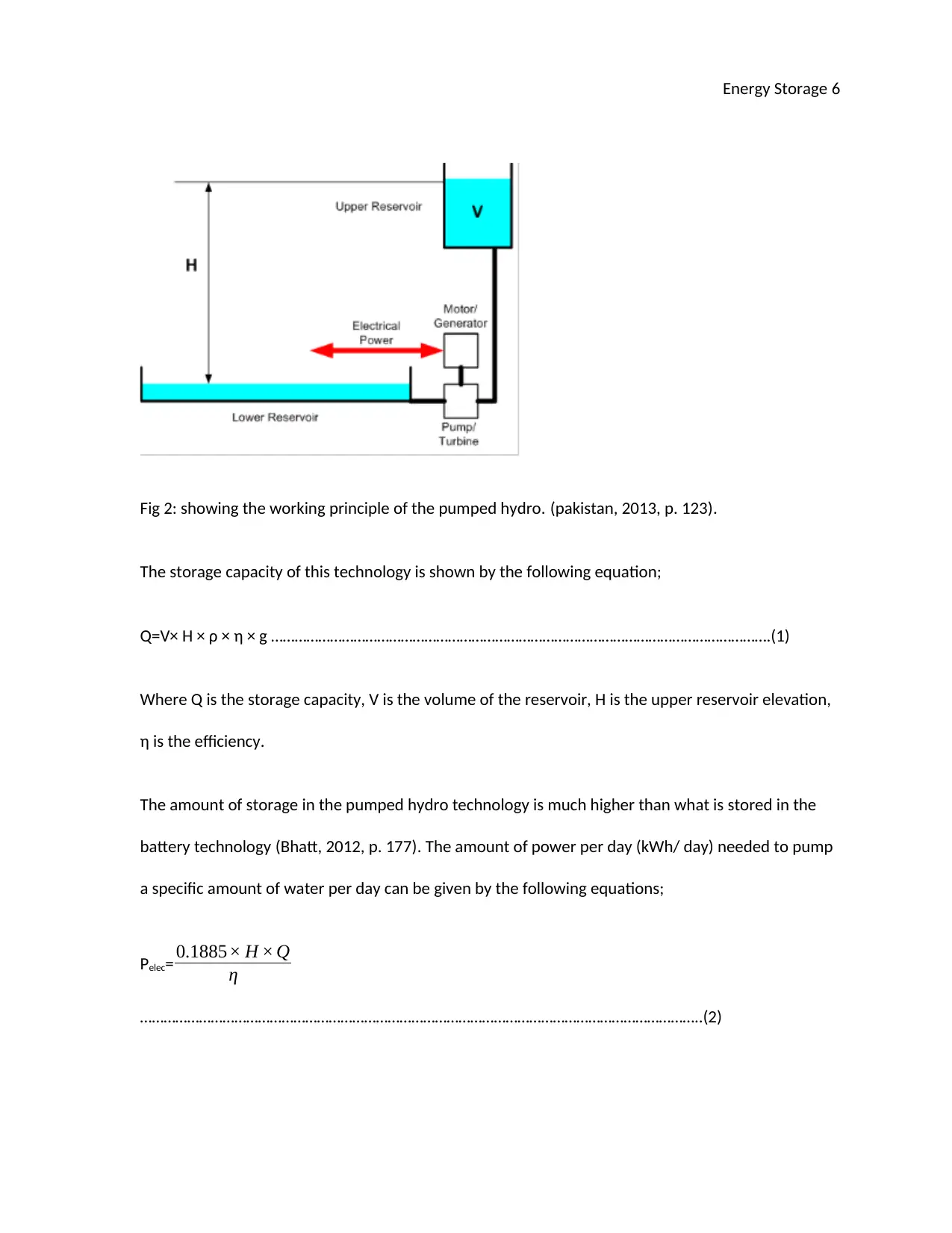
technology to have an efficiency of about 82%. The diagram below summarises the process
(Bany, 2012).
Energy Storage 6
Fig 2: showing the working principle of the pumped hydro. (pakistan, 2013, p. 123).
The storage capacity of this technology is shown by the following equation;
Q=V× H × ρ × η × g ……………………………………………………………………………………………………………….(1)
Where Q is the storage capacity, V is the volume of the reservoir, H is the upper reservoir elevation,
η is the efficiency.
The amount of storage in the pumped hydro technology is much higher than what is stored in the
battery technology (Bhatt, 2012, p. 177). The amount of power per day (kWh/ day) needed to pump
a specific amount of water per day can be given by the following equations;
Pelec= 0.1885× H × Q
η
……………………………………………………………………………………………………………………………..(2)
Energy Storage 7
Where Pelec is electrical power in watts, H is the head pressure, Q is the quantity of water and η is the
efficiency of the operation of the system. It is clear from the above equation that the electrical
power can be increased when the head pressure H and the amount of water Q is increased. And
from the law of energy which goes`` energy can never be created or destroyed but it is transformed
from one form to another,`` the potential energy will be transformed to kinetic energy which is then
employed to generate electrical power (Williams, 2013, p. 122). This can be illustrated using the
below equation (Nelson, 2014, p. 67).
Potential energy = kinetic energy
mgH = ½ mv2 ………………………………………………………………………………………………………………………………(3)
Where m is the mass of water, g is the gravitational acceleration, H is the pressure head and v is the
speed of the flowing water (Papers, 2011, p. 89).
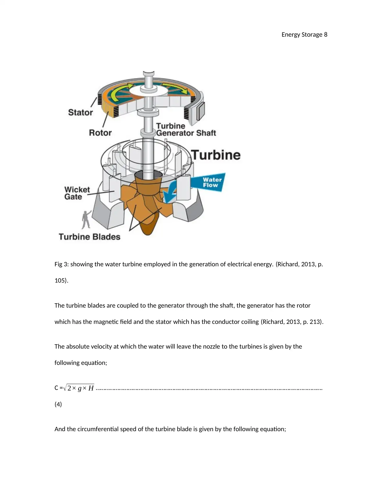
In the power house, there is water turbine which is a rotary device for converting the potential
energy and kinetic energy (mechanical energy) to electrical energy. The water is allowed to
approach the blades of the turbine in such a way that the blade will have a continuous movement
with minimum drag and abrasion (Pardalos, 2008, p. 12). This is illustrated in the figure below;
Paraphrase This Document
Need a fresh take? Get an instant paraphrase of this document with our AI Paraphraser
Energy Storage 8
Fig 3: showing the water turbine employed in the generation of electrical energy. (Richard, 2013, p.
105).
The turbine blades are coupled to the generator through the shaft, the generator has the rotor
which has the magnetic field and the stator which has the conductor coiling (Richard, 2013, p. 213).
The absolute velocity at which the water will leave the nozzle to the turbines is given by the
following equation;
C = √2× g× H ………………………………………………………………………………………………………………………………….
(4)
And the circumferential speed of the turbine blade is given by the following equation;
Energy Storage 9
U= ½ √2× g× H …………………………………………………………………………………………………………………………. (5)
Where C is the velocity of the water from the nozzle, g is the gravitational acceleration and H is the
pressure head from the penstock (Marxgut, 2012).
MECHANICAL DESIGN FEATURE MATERIALS AND
CONSTRUCTION
Some of the design feature materials of the pumped hydro energy includes the following
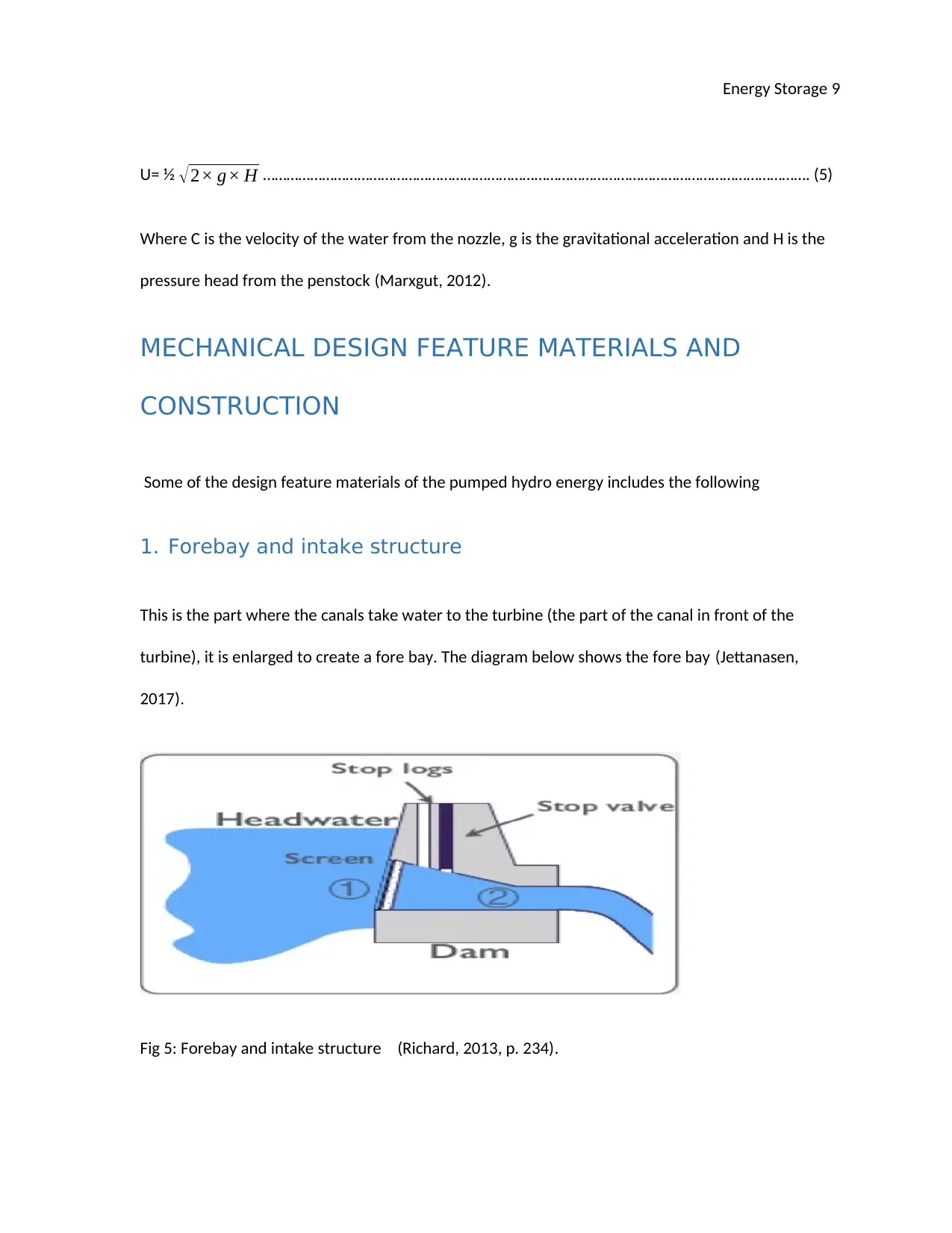
1. Forebay and intake structure
This is the part where the canals take water to the turbine (the part of the canal in front of the
turbine), it is enlarged to create a fore bay. The diagram below shows the fore bay (Jettanasen,
2017).
Fig 5: Forebay and intake structure (Richard, 2013, p. 234).
Energy Storage 10
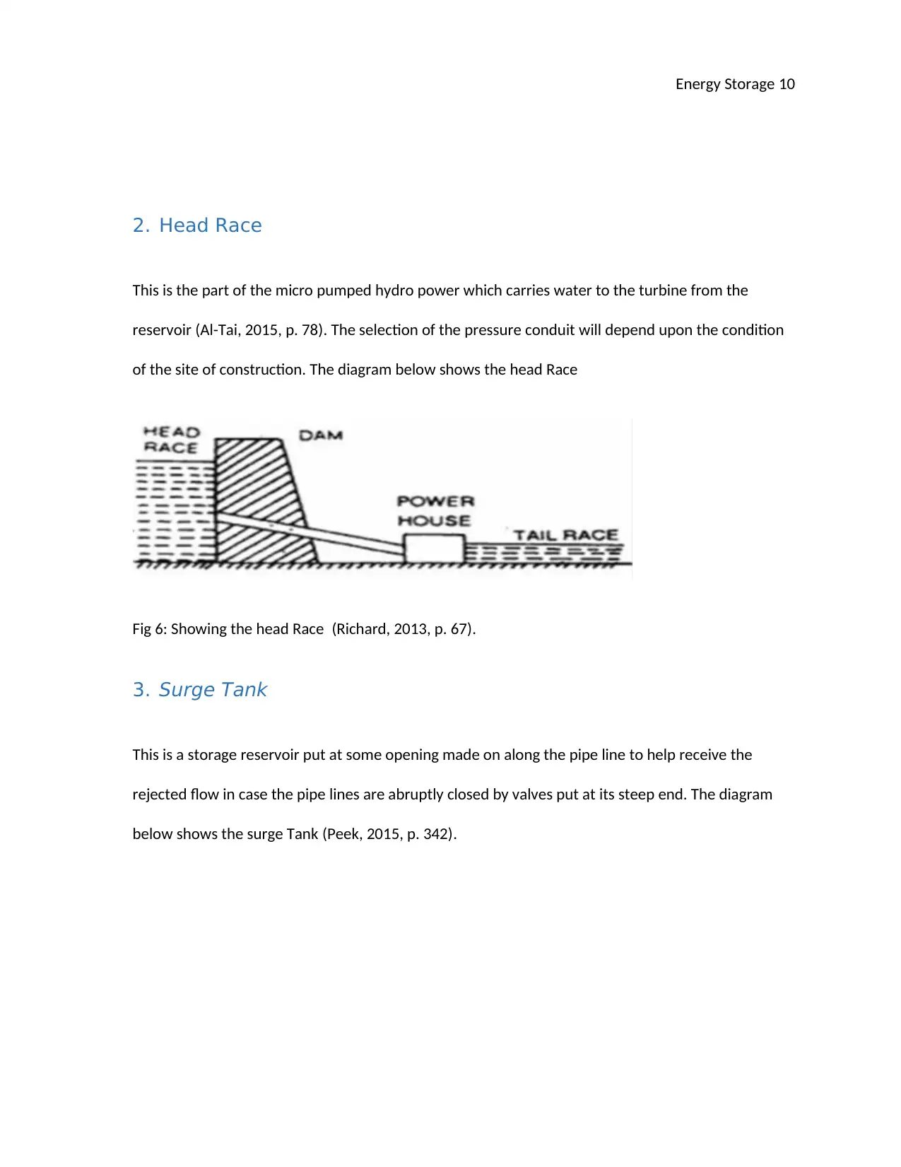
2. Head Race
This is the part of the micro pumped hydro power which carries water to the turbine from the
reservoir (Al-Tai, 2015, p. 78). The selection of the pressure conduit will depend upon the condition
of the site of construction. The diagram below shows the head Race
Fig 6: Showing the head Race (Richard, 2013, p. 67).
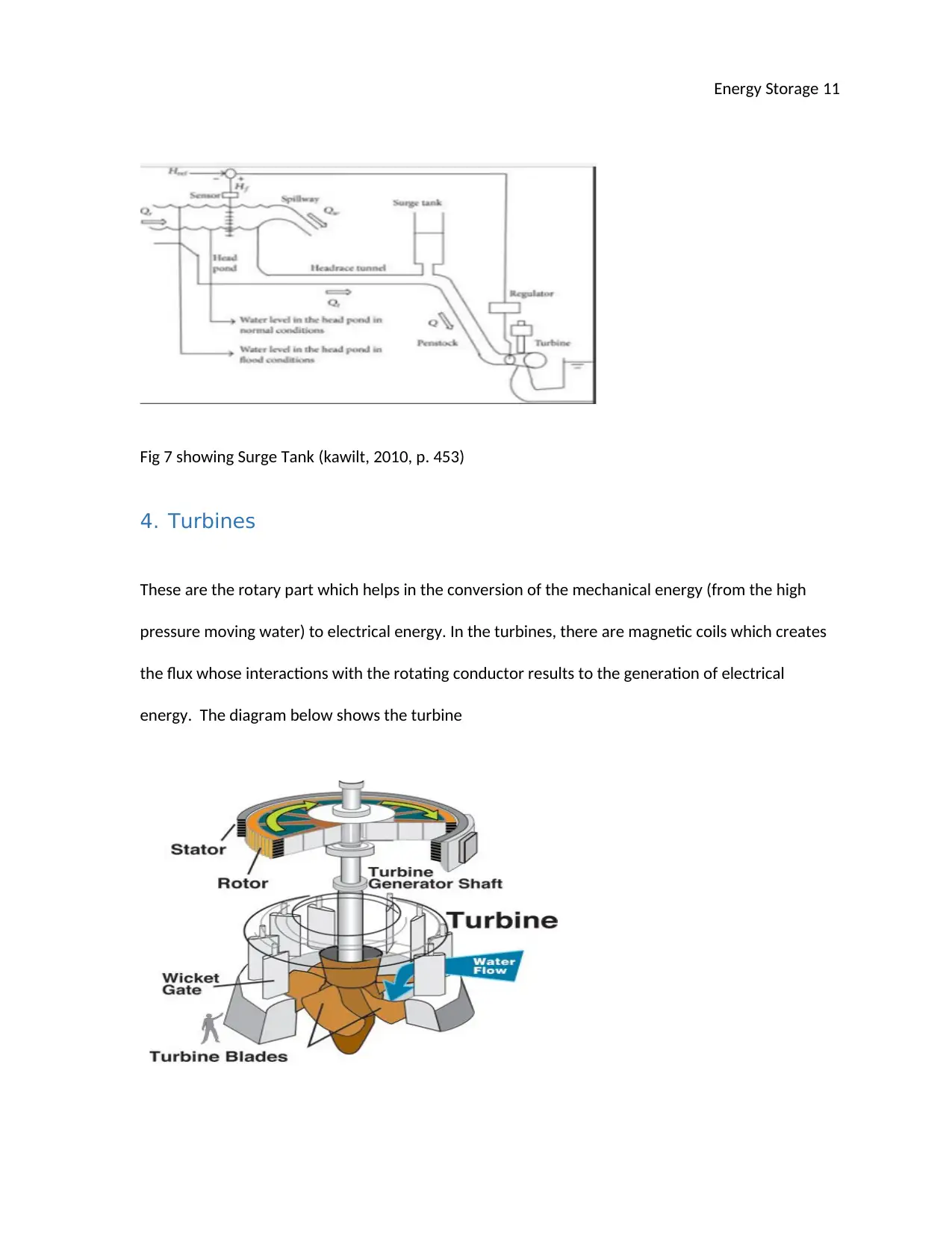
3. Surge Tank
This is a storage reservoir put at some opening made on along the pipe line to help receive the
rejected flow in case the pipe lines are abruptly closed by valves put at its steep end. The diagram
below shows the surge Tank (Peek, 2015, p. 342).
Secure Best Marks with AI Grader
Need help grading? Try our AI Grader for instant feedback on your assignments.
Energy Storage 11
Fig 7 showing Surge Tank (kawilt, 2010, p. 453)
4. Turbines
These are the rotary part which helps in the conversion of the mechanical energy (from the high
pressure moving water) to electrical energy. In the turbines, there are magnetic coils which creates
the flux whose interactions with the rotating conductor results to the generation of electrical
energy. The diagram below shows the turbine
Energy Storage 12
Fig 8: showing the water turbine (Richard, 2013).
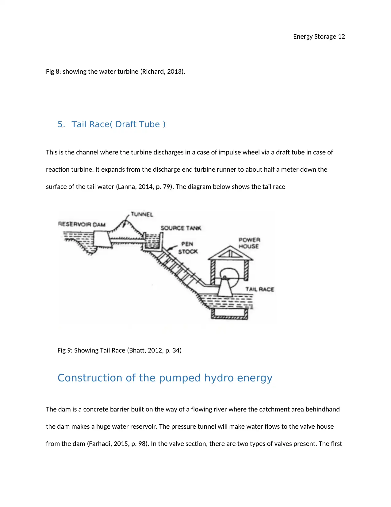
5. Tail Race( Draft Tube )
This is the channel where the turbine discharges in a case of impulse wheel via a draft tube in case of
reaction turbine. It expands from the discharge end turbine runner to about half a meter down the
surface of the tail water (Lanna, 2014, p. 79). The diagram below shows the tail race
Fig 9: Showing Tail Race (Bhatt, 2012, p. 34)
Construction of the pumped hydro energy
The dam is a concrete barrier built on the way of a flowing river where the catchment area behindhand
the dam makes a huge water reservoir. The pressure tunnel will make water flows to the valve house
from the dam (Farhadi, 2015, p. 98). In the valve section, there are two types of valves present. The first
Energy Storage 13
one is master sluicing valve and the other one is an automatic valve. The master valves regulate the
flowing water downstream and isolate valves automatic to stop the flowing water when the electrical
load is suddenly thrown off from the plant (Jiang, 2013, p. 90).
The penstock which is a steel pipeline of appropriate cross-sectional area connected amid
the powerhouse valve house. The water flows down from upper valve house to lower powerhouse
through this penstock (Pruckner, 2016, p. 126). Down in the powerhouse, there are alternators and
water turbines with step-up transformers to step up the voltage after generation and switchgear
systems to help produce and then facilitate transmission of electricity to the required places
through the grid.
Application and where currently operational
The pumped hydro system is applied in the generation of electrical energy where the water stored in
the reservoir is allowed to flow down the power house at a very higher pressure which then rotates the
water turbine to generate the electrical energy (Belmans, 2010, p. 547). Basically, this system is
currently operational in most countries in the world; just to mention a few China, India, USA, UK, and
Netherlands among others.
Design
The power to be delivered should be 0.5 MVA at a frequency of 50 Hz
From
Paraphrase This Document
Need a fresh take? Get an instant paraphrase of this document with our AI Paraphraser
Energy Storage 14
P.F = KW
KVA …………………………………………………….……………………………………………………………………………………
7
And power delivered in Watts is given by the following
Power = ( η×g×Q×H)
Where η is the operational efficiency g is the gravitational force Q is the discharge and H is the
pressure head of the power station.
The efficiency of operation is not given and in most cases, it ranges between 85 to 92% for the
hydroelectric power. Hence in this design, we will use 90 %. The gravitational pull is 9.81.
From
V = Q
A ……………………………………………………………………………………………………………………………………………8
And the discharge is not given hence we can take arbitrary value of 225m3/s which will work best for
this design.
A = π
4 D2
And also from the following
Q= AV …………………………………………………………………………………………………………………………………………. 9
Energy Storage 15
Taking the area of the penstock delivering water to the turbine to be 0.7855m2
0.7855 = π
4 D2
0.7855 = 3.142
4 D2
D2 = 1
D= 1 and the radius is 0.5m
From equation 9
225= 0.7855 V
V= 286.44
Height is taken as 100 m
Power delivered in kW is given as below
P= 0.9 × 9.81 ×225 × 100× 100
P = 216310.5 kW
P.F = 216.63 kW
500 kVA
Energy Storage 16
P.F= 0.43 or 43 %
Rotating speed of the turbine is calculated using the frequency and the number of poles as below
N = 120 f
P ……………………………………………………………………………………………………………………………………10
Where N is the rotational speed in RPM f is frequency and p is the number of poles which is taken as
4 for this design.
N = 120× 50
4
N= 1500RPM
The overall schematic diagram of the pumped hydroelectric power is shown below
Fig 10: Showing the overall schematic diagram of the pumped hydroelectric power (Thomas, 2013)
Secure Best Marks with AI Grader
Need help grading? Try our AI Grader for instant feedback on your assignments.
Energy Storage 17
Summary
The local micro pumped hydroelectric power plant enable sufficient supply of electrical energy
where water will be stored in the reservoir where there is enough rain and then used during the dry
spell when there is no sufficient amount of water. Hence the pumped hydro power technology is
employed in the small streams which stores energy to be used in the local homes which are around
the stream and the power generated is on-grid (connected to the grid) hence it is exclusively for
domestic use but the excess produced energy is sold by connecting to the grid.
FLYWHEEL ENERGY STORAGE
A flywheel is a heavy rotating wheel which is employed to increase the momentum and in most
cases it used in the storage of electrical energy in form of kinetic energy. And in some cases flywheel
is simply employed in the generation of electrical energy. This is done through conversion of
mechanical energy to electrical energy.
OPERATION
Mechanical or electrical energy is employed to spin the flywheel to higher speeds and
rotate to store energy. The higher the rotation speed the higher the sum of energy stored in
the flywheel. Thus the stored energy can then be accessed at any time it is required. The
flywheel will be kept rotating as long as the energy is not retrieved, and the energy is
retrieved from it, its speed will reduce when the energy is retrieved from it. The
transformation of energy is done into kinetic energy in flywheel is obtained from solar
Energy Storage 18
energy among other forms of renewable sources of energy (Brown, 2015, p. 88). The spine
energy is kept in the state of rotational kinetic energy. Just as the kinetic energy of an object moving
in a straight line is given by this equation:
E = ½mv2 ………………………………………………………………………………..11
The equation for the rotational kinetic energy is shown below;
K. E = ½ I ῳ2 ………………………………………………………………………………12
Where ῳ is the angular velocity ( rotational velocity) given in Rad/ sec and I is the moment
of inertia of the flywheel ( this is simply the ability of the object to resist any change in its
angular velocity) and it is given by the below equation;
I=kMr2 …………………………………………………………………………………….13
Therefore the overal equation becomes ;
E=½ ῳ2 kMr2 ……………………………………………………………………………..14
Where M is the flywheel mass in kg, r is the radius of the rotating flywheel and k is the
inertial constant.
Since the kinetic energy K.E in the rotating flywheel is given by;
K. E=½ I ῳ2 …………………………………………………………………………………15
Energy Storage 19
Therefore bthe change in the kinetic energy of the flywheel system is given by the below
equation
K.E = K. E=½ I (ῳmax2 - ῳ min2) …………………………………………………………..16
From the above equations, the energy will increase if the value of omega (ῳ) and the
moment of inertia ( I) is increased. The value of I can be increased through locating more
mass on the outer side of the flywheel as much as possible. But the mass added will only be
limited by some mechanical limitations to ensure that it operates effectively (Simeonov,
2012).
MATERIALS USED IN DESIGN
Fig 15: Showing the flywheel energy storage device. (Ming, 2011).
Paraphrase This Document
Need a fresh take? Get an instant paraphrase of this document with our AI Paraphraser
Energy Storage 20
i. Rotor: This is the rotating part of the flywheel. This is made of carbon fiber
composite which is light but has higher tensile strength. The greater and the heavier
diameter of the rotor, the more the energy which the flywheel can store in the rotor.
Fig: showing examples of rotor
ii. Bearing: The flywheel will spine on the mechanical bearing, the bearing is very
significant in the assembly. This is because of the bearings will help to reduce the
friction during the spinning of the flywheel.
Fig : Showing bearings
iii. Ceramics
Energy Storage 21
Fig : showing examples of ceramics
iv. Lead alloys
Fig : showing an example of lead alloys
CONSTRUCTION OF FLYWHEEL
The two flywheel are fabricated aimed at the flywheel system for enegy storage, this is done
in conjuction with the two dynamos. The dynamos are joined to the flywheel in order to
enhance conversion of the mechanical to electrical energy.Starting at the dynamo the energy
produced will be in form of DC which can be converted to AC by the use of the
commutators. By the use of heavy flywheel gives a lot of energy since the flywheel has a lot
of momentum.
Energy Storage 22
WHERE THIS IS EMPLOYED +
The flywheel has been employed in the storage of electrical energy many countries over the world
just to mention a few China, India, USA, UK, and Netherlands among others.
DESIGN
Flywheel rotor: The energy stored in a flywheel is determined by the material and shape of
the rotor.
Fig: showing flywheel rotor
It is the square of its angular velocity and proportional linearly to the moment of inertia.
Where E is the kinetic energy stored which is 0.5 MVA, ɯ is the angular velocity, and I is
the moment of inertia (McMurry, 2015). This design is expected to deliver 0.5 MVA to a 50
Hz grid system on a short-term basis depending on the evaluation of the restrictions that
would be in place.
Secure Best Marks with AI Grader
Need help grading? Try our AI Grader for instant feedback on your assignments.
Energy Storage 23
The value of E can be converted to Watts by:
Power factor = 0.9
KVA = kW/Power factor
Power in kW = KVA × Power factor
= 500KVA × 0.9
= 450kW
The flywheel will be rotating at an angular velocity of 5, 000 rpm, the value of the moment
of inertia I can be gotten by:
450000W = ½ × I × 5000 rpm;
I = 180 kgm2
The flywheel’s useful energy within the range of maximum velocity and minimum velocity
can be gotten by:
Where E is gotten from real power = 450kW, Energy produced in every hour by the flywheel
will be: Power = Energy*Time, Time = 1hour, therefore Energy = 405,000Joules
Energy Storage 24
For a cylinder flywheel that is hollow of inner radius ‘a’ and outer radius b, the moment of
inertia can be gotten by:
For this design a = 15cm, b = 16.68cm and m = 6 kg
For a flywheel with mass density ɋ and length h, the energy E and moment of inertia I can be
obtained by:
Mass density, ɋ = 1.9× 10⁻³kg/m3 = 1.9g/cm3
Length, h = 5m since E = 450,000 J
To attain the required energy of 450, 000J, a high-speed flywheel of up to 5, 000 rpm with
being used.
Motor-Generator: The electrical machine that would be used as motor-generator for
induction to the flywheel will be permanent magnet synchronous. This is because it has low
rotor losses, high power density, and higher efficiency.
Energy Storage 25
Fig: showing motor generator
The following are some of the specifications of the permanent magnet synchronous
induction machine:
High efficiency of about 95.5%
High specific power of about 1.2 KW per kg
Sinusoidal vector control
Low maximum/base speed of 2
Medium torque ripple of 10%
Size of 2.3 L/kW (Gogus, 2011)
Paraphrase This Document
Need a fresh take? Get an instant paraphrase of this document with our AI Paraphraser
Energy Storage 26
REAL VIEW OF FLYWHEEL
Fig 7: Showing the real view of flywheel. (Minoli, 2012, p. 45).
SUMMARY
Flywheel has been employed in the storage of electrical energy for a relatively longer period now.
This is because of large amount of energy which this technique is able to store due to higher
momentum of the rotating big wheels. The higher the rotation speed the higher the amount of
stored energy in the flywheel. Thus the stored energy can then be accessed at any time it is
required. The flywheel will be kept rotating as long as the energy is not retrieved, and the
energy is retrieved from it, its speed will reduce when the energy is retrieved from it.
Energy Storage 27
Bibliography
Alipanahi, B. ( 2013) Proceedings of the IEEE. 2nd ed. Florida: IEEE.
Al-Tai, M. (2015) Review of current and future electrical energy storage devices. 2nd ed.
Amsterdam: IEEE XPLORE.
Bajpai, P. (2016) hydro generation plant. 2nd ed. Chicago: IEEE.
Baker, R. M. (2011) Design and calculation of induction heating coils. 2nd ed. Chicago: IEEE.
Bany, J.(2012) electrical energy storage technology. 3rd ed. New Delhi: IEEE.
Belmans, R.(2010) Integration of energy storage in distribution grids. 1st ed. Hull: IEEE.
Bhatt, S. (2012) Land and People usage in the generation of electrical energy through water. 2nd ed.
New Delhi: IEEE.
Bilmate, H.(2013) Technologies used in the storage of electrical energy. 2nd ed. Washington: IEEE.
Bizuayehu, W.(2014) Electrical Energy Storage Systems: Technologies' State-of-the-Art, Techno-
economic Benefits and Applications Analysis. 2ND ed. London: IEEE XPLORE.
Brandeis, L. (2016) Analysis of electrical energy storage technologies for future electric grids. 2nd ed.
Hawaii: IEEE.
Richard, W. (2013) Performance and Testing of Thermal Interface material used in making the water
turbines. 1st ed. hull: IEEE.
Energy Storage 28
Thomas, T. (2013) The principle of energy generation. Hull: IEEE.
Webinars, D.(2012) Why a Feasibility Study is Important in starting hydro power. 1st ed. Chicago:
IEEE.
Williams, P. (2013) Transformation of energy from potential to kinetic energy. s.l.: IEEE.
Peek, G. (2015) The United States of storage [electric energy storage]. 3rd ed. HAWAII: IEEE.
Petlyuk, B. (2012) The amount of discharge in a reservoir affects the energy produced. 2nd ed.
London: IEEE.
Pruckner, M.(2016) Modeling the impact of electrical energy storage systems on future power
systems. 1st ed. London: IEEE.
Put, K. (2013) On-grid connection regulations. 2ND ed. Chicago: IEEE.
Ramesh, A. (2011) Construction of a good power house. 3rd ed. London: IEEE.
Secure Best Marks with AI Grader
Need help grading? Try our AI Grader for instant feedback on your assignments.
Energy Storage 29
Question 2
Table of content
1 ..................................................................................................................................................Safety
2......................................................................................................................Connection Arrangement
3..................................................................................................................................Protective devices
4........................................................................................................................................Design aspect
5................................................................................................................................Operational aspect
a.....................................................................................................................................Zone Protection
b......................................................................................................................................Fault detection
c...........................................................................................................................Differential protection
d..........................................................................................................................Overcurrent protection
e...............................................................................................................................Distance protection
f..........................................................................................................................Overvoltage protection
g.......................................................................................................................Undervoltage protection
Energy Storage 30
h....................................................................................................................Reverse-current protection
g. Thermal protection
a. Grid compliance is a technical specification that outlines the parameters a facility connected to
a public electrical system need to satisfy to enable secure, safe and cost effective operation of
the electric system.
The national grid rules and regulations regarding the connection of the generators on the
design and the operational aspect basically entail the checkpoints or the yardstick referred to when
the connection is of the 3 phase is made for a synchronous generator. The requirement for the
connection of the generator is viewed as one of the significant drivers for generating harmonised
solutions for the connection of the synchronous generators. And products necessary for an efficient
pan-European market in generator technology (Krul, 2011). These standards employed by electrical
installation also help to ensure that there is a uniformity in the design. The regulations will as well
Energy Storage 31
help to ensure that the whole circuit work as it should be without making any fault mistake. They
also provide then guideline on how a perfect installation should be undertaken in any design
project. The national regulations for the connection can be well understood under the following
subtitles of the regulations
1. Safety
The generation unit should not execute a safety hazard to personnel and stuffs working on
the generation and distribution network. Before any work is started the personnel should ensure
that there is no current flowing in the live conductors. And this should be confirmed by the one
working on it and he should personally confirm this by locking the main switch after putting it off.
DC/AC Inverters employed in photovoltaic arrays should always comply with the appropriate
electrical safety requirements of IEC 62109-1, 2. Safety in electrical installation should be given
higher priority since if there is fault in the electrical line it may lead to fire risks which may results to
loss of property as well as loss of life at the same time.
2. Connection Arrangement
The optimum value for the rating of the production unit allowed for the three-phase power
plant at any time is taken to be 100MVA. And there is also a configuration of single phase to three
phase during the generation of the electrical power (Xhi, 2011). Where an energy storage system is
installed, the storage system will not contribute to the overall available exporting generation
capacity. The cables employed in the connection should as well be the recommended ones, for
example, 6mm2 and a correct insulation is required depending on the amount of the voltage
Paraphrase This Document
Need a fresh take? Get an instant paraphrase of this document with our AI Paraphraser
Energy Storage 32
connected to the grid. The heights of the supports should be relatively high enough to ensure that
there is no damage caused by the cables in case of the overhead transmission of electrical energy.
The rules which governs the connection arrangement of the electrical components will ensure that
the circuit
Production units with a capacity more than 100MVA should be balanced uniformly over the
3 phases with a tolerance which is not more than 5 % of the inverter output between any
two lines of the 3 phase. Production units with a capacity more than 30kW must be 3 phase systems
like in this case with the production balanced evenly amongst the 3 phases. Only if precisely stated
by ActewAGL, the rating limit for a 3 phase IES in an individual installation will be roughly to 100
MVA. The correct ratings of this generator will ensure that there is no overload in the generators as
well as under usage of the generators during the production of electrical energy (Put, 2013, p. 34).
3. Protective devices
After generation of electrical energy, the voltage will be stepped up to the required amount while at
the same time the current will be stepped down. This will help to power loss through the following
equation.
P= I2R . . . . . . . . . . . . . . . . . . . . . . . . . . . . . . . . . . . . . . . . . . . . . . . . . . . . . . . . . . . . . . . . . . . . . . . . . . . . . 11
Now depending on the amount of current at any given point a suitable protective device like fuse or
circuit breakers should be employed. This will basically help to safeguard the appliances
Energy Storage 33
ahead of the flow of the current. And in some case it will even provide safety to human by
avoiding the fire risks either in generation plant or in substations. These protective devices
will either blow off (fuse) or triples (circuit breaker). The rules for the protection always
help to make design uniform and effectively operational. For example, the circuit breakers
for lighting employs 5 A, 10 A and 15 A depending on the load connected on a single circuit
breaker and for the socket outlets the rules and regulations for the design employs the use
of 30 A, 60 A depending on the load which will be conn
4. Design aspect
For the design of the generation station, there are some aspects which must be adhered with to
ensure a perfect operation, generation and transmission of electrical energy. These aspects must
conform to the IEEE standards of electrical engineering practice. For example, during the design of
the generation station, the electrical energy should be done at 11kV then stepped up and at the
consumer's the voltage should be at 415 V three phase which will be 240 V at single phase. The
variation allowed for this voltage is only ±10V. And for the AC voltage, the generating station must
ensure that the frequency is always 50 Hz, this is achieved by applying equation 10.
N = 120 f
P , Therefore the station will have to select the number of the pole to be used in the
generator. Once that is set. Then the speed of the generator can be calculated from equation 10 and
then it is maintained at that speed to ensure a constant frequency.
Energy Storage 34
5. Operational aspect
During the operation of the production and distribution of electrical energy, the station should
ensure that all the parameters operate as designed and as intended. And if in any case there is a
fault, then troubleshooting should be done and then fixed as soon as possible. If the problem was
with may be circuit breakers or fuse, then the replacement should be done with the same
specification of the earlier one (only if the design specification was done perfectly). The sizes of the
cables and the values of the protective devices should be used as required to ensure that all designs
operate as needed to avoid any operational fault.
ii.
Secure Best Marks with AI Grader
Need help grading? Try our AI Grader for instant feedback on your assignments.
Energy Storage 35
Fig 11: Showing power connected to the grid with the protective devices (Green, 2011).
The electrical power is generated from different generation stations being the solar, wind, nuclear,
hydroelectric and then all are connected to the grid (Green, 2011, p. 654). From the grid, the
electrical energy is stepped up and transmitted as seen in figure 11 above. The electrical energy at a
relatively higher voltage and in most cases higher currents too, therefore there is a higher need to
use the protection and below are some of the very important protections employed during
generation and transmission to and from the grid (Hurm, 2012, p. 97). Basically, these protections
safeguard the electrical devices in figure 11 above (like the relay and the transformers)
Energy Storage 36
a. Zone Protection
In light of using this, the system of electrical energy is put into five different protection zones: These
zones include
i. generators;
Protection in the generator zones will actually help to avoid any overheating of the magnetic coils
which are in the armature. If these coil are subjected to a very high current beyond their rating the
coils may blow out. The generators will actually operate well at the designed values. The protection
will hence ensure that the windings do not receive higher currents.
ii. transformers;
Transformers also operates on the primary and secondary winding coils. These windings depending
on the turn ratio. If these coil are subjected to a very high current beyond their rating, then the
transformer may not operate as designed. The generators will actually operate well at the designed
values. Therefore, the protection is highly required to ensure that the current which flows through
the coils are as designed.
iii. transmission and distribution lines
In the transmission and distribution, there are cable sizes which are used depending on the current
which are being transmitted and distributed. Therefore, protection is highly significant to ensure
that the cables of the transmission and distribution are highly protected.
Energy Storage 37
iv. buses;
Buses are simply the cables (copper cables) employed in the transmission of signals. The buses
convey current of small magnitude. Therefore, higher currents should be reduced to smaller
tolerable currents through protection.
Fig: showing a real view for a bus
v. Motors
Motors work in the same ways as the generators but in opposite direction. Protection in the motor
zones will actually help to avoid any overheating of the magnetic coils which are in the motor
armature. If these coil are subjected to a very high current beyond their rating the coils may blow
out. The motors will actually operate well at the designed values. The protection will hence ensure
that the windings do not receive higher currents.
Paraphrase This Document
Need a fresh take? Get an instant paraphrase of this document with our AI Paraphraser
Energy Storage 38
Each zone signifies a group of protective relays with the linked electrical device picked to
inductee isolation and correction of that zone for all expected excruciating situations. The
discovery is undertaken through protecting relays having a circuit breaker employed as to
disconnect the electrical device physically from being blown out (Krul, 2010, p. 377).
Fig 12: Showing the zone protection (Krul, 2010).
b. Fault detection
This protection is realized through various mechanisms that constitute the detection of variations in
temperature voltage levels and electric current, the ratio of current to voltage, power direction, and
contrast of the electrical measures moving into protected zones with the magnitudes moving out.
c. Differential protection
This type is significant and highly employed protection mechanism. It will equate currents flowing
and then detect mistakes in suitable protection area. Current on whichever point of the safeguard
will decrease the currents at the primary side of the transformer to lesser secondary values of which
these include contributions to the relay (Alipanahi, 2013). Nonetheless, for interior misfortune, the
subordinate currents will enhance movement via the relay.
Energy Storage 39
d. Overcurrent protection
All system should employ protection to avoid unusually extraordinary currents from making the
electrical devices to overheat which in some cases may result in their mechanical failures (Hossain,
2013). A power system having overcurrent always shows that the current is being averted from its
usual path by a short circuit to another unusual direction. In low-voltage, distribution-type circuits
like the ones at homes, sufficient overcurrent protection can be achieved by use of fuses which will
blow out when the current exceeds a preset value.
In some cases, small thermal-type circuit breakers are used to assist in protecting overcurrent for
this type of circuit. As a result of increase in system size and circuit, the problems linked to the
interlude of great burden currents command the application of power circuit breakers (John, 2013,
p. 312). This activates the trip circuit of a specific circuit breaker, making it exposed and hence
detach the fault (Baker, 2011, p. 65). The circuit breakers are illustrated in figure below;
Fig 13: Showing circuit breakers (Baker, 2011, p. 54).
Energy Storage 40
The circuit breakers are most employed protection for the current control, the circuit breaker is
more effective than the fuse since when it triples it can be restored. And this only happens when
there is excess current drawn from the circuit under protection.
e. Distance protection
These protections operate on the arrangement of increased current and a reduced voltage caused
by faults. They are extensively used safeguarding larger voltage lines. Its significant benefit is that
the zone of operation is defined by the resistance line
f. Overvoltage protection
Lightning occurring in a location close to the power lines can result to a short-time overvoltage and
likely interruption of the insulation of the line. Safeguard for these surges contains lightning
arresters which are always coupled amid the ground and lines. The protection of Overvoltage is
rarely used somewhere else except at the generators. The diagram below shows the surge and
lightning protection. If excess voltage (more than the designed value) is not protected from and
Secure Best Marks with AI Grader
Need help grading? Try our AI Grader for instant feedback on your assignments.
Energy Storage 41
electrical then the device may actually blow out during the operation hence it will be faulty.
Fig 14: Showing surge and lightning protection device (Baker, 2011, p. 45).
g. Under-voltage protection
This protection always gives the circuits providing control to motor piles. The condition of low-
voltage always makes motors to lure more currents, which causes to harm the motors. When a
condition of low-voltage advances during the operation of the motor the relay will detect this
situation and detaches the motor from the operation. The under voltage need to be protected to
ensure that the component (device) receive the voltage for which it is designed for.
h. Reverse-current protection
This is the type of protection is employed when there is a change in the usual current direction
showing an anomalous situation in the system. For an AC circuit, inverse current denotes a shift in
phase of the current of about 180° from the usual phase. This is essentially a variation in power flow
path and is also fixed by AC relays directional (Ndii, 2012, p. 567).
Energy Storage 42
Fig Showing reverse current protection (Green, 2011).
g. Thermal protection
Generators and Motors (AC machines) are predominantly subject to overheating because of the
overloading and the mechanical friction which occurs during the operation. And as the extreme
temperatures result to increment in losses and worsening of insulation in the machine. Henceforth
temperature-sensitive constituents are put into the machine forming a portion of a bridge circuit
employed to deliver current to a relay. After realization of a preset temperature, the relay works,
starting to open circuit breaker or giving an alarm through a buzzer (Hurt, 2016, p. 113). The
windings will generate some heat which needs to be controlled to ensure protection of the coils of
the generators, motors and transformers’ coils. The excess heat develop May in most cases results
to fire risks as always seen in the transformers.
Energy Storage 43
Fig showing thermal protection (Green, 2011).
Bibliography
Brown, W. H. (2015) Introduction to General technology in the generation of electrical energy. 2nd
ed. New Delhi: IEEE.
Farhadi, M. (2015) Energy storage systems for high power applications. 3rd ed. Toronto: IEEE.
Green, P. (2011) Circuit diagram for the electrical connection. 2nd ed. Hawaii: IEEE.
Hossain, M. (2013) IEEE Access. 3rd ed. Toronto: IEEE.
Paraphrase This Document
Need a fresh take? Get an instant paraphrase of this document with our AI Paraphraser
Energy Storage 44
Hurm, J. (2012) IEEE Guide for Maintenance, Operation, and Safety of Industrial and Commercial
Power Systems. 2nd ed. Hawaii: IEEE.
Hurt, J.(2016) IEEE Recommended Practice for Electric Power Distribution for Industrial Plants. 2nd
ed. Hull: IEEE.
Jettanasen, C. (2017) Generation and storage of electrical energy. 1st ed. Stoke: IEEE XPLORE.
Jiang, L. (2013) Grid-Level Application of Electrical Energy Storage: Example Use Cases in the United
States and China. 2nd ed. Beijing: IEEE.
John, G. (2013) Electrical protections. 2nd ed. Hull: IEEE.
kawilt, K. (2010) Guidelines for Safe Storage and Handling of Reactive Materials with a high tensile
strength. 4th ed. Hull: IEEE.
Krul, J. (2011) Regulations of sychnrouns motor connection. 2nd ed. Hull: IEEE.
Krul, W. (2010) Electrical Engineering. 2nd ed. Berlin: IEEE.
Lanna, A. (2014) Electric energy storage systems integration in distribution grids. 4th ed. London:
IEEE.
Marxgut, C. (2012) A generic topology for electrical energy storage systems. 2nd ed. Hull: IEEE.
McMurry, J. E. (2015) How pressure high-pressure head can be achieved. 4th ed. Amsterdam: IEEE.
Energy Storage 45
Ndii, D. (2012) IEEE Recommended Practice for Protection and Coordination of Industrial and
Commercial Power Systems. 3rd ed. Chicago: IEEE.
Nelson, V. (2014) Introduction to Renewable Energy. 4th ed. Chicago: IEEE.
pakistan, M. (2013) Project Preparation/Feasibility for the energy storage technologies. 1st ed.
Quetta: IEEE.
Papers, A. (2011) American Society of Mechanical Engineer. 2nd ed. Florida: IEEE.
Pardalos, P. (2008) The higher pressure head results in a higher energy generated. 2nd ed. Chicago:
IEEE.
1 out of 45
Related Documents
Your All-in-One AI-Powered Toolkit for Academic Success.
+13062052269
info@desklib.com
Available 24*7 on WhatsApp / Email
Unlock your academic potential
© 2024 | Zucol Services PVT LTD | All rights reserved.