Faculty of Engineering, Computing and Science

Verified

Added on  2022/08/24

|9
|2398
|32
AI Summary
tabler-icon-diamond-filled.svg

Contribute Materials

Your contribution can guide someone’s learning journey. Share your documents today.
Document Page
Faculty of Computing, Engineering and Science
Assessment Cover Sheet and Feedback Form 2019-20
Module Code:
CS1S465
Module Title:
Computer Systems Concepts
Module Team:
Alun King, Keith Norris, Keith
Verheyden
Assessment Title and Tasks:
Set Tasks - not-time constrained 1
Assessment No.
1
Date Set:
28-Oct-2019 09:00
Submission Date:
24-Jan-2020 23:59
Return Date:
21-Feb-2020 09:00
IT IS YOUR RESPONSIBILITY TO KEEP RECORDS OF ALL WORK SUBMITTED
Marking and Assessment
This assignment will be marked out of 100%
This assignment contributes to 50% of the total module marks.
Learning Outcomes to be assessed (as specified in the validated module
descriptor https://icis.southwales.ac.uk/ ):
1) Demonstrate knowledge of key theoretical principles of computer systems.
Provisional mark only: subject to change and / or confirmation by the Assessment
Board
tabler-icon-diamond-filled.svg

Secure Best Marks with AI Grader

Need help grading? Try our AI Grader for instant feedback on your assignments.
Document Page
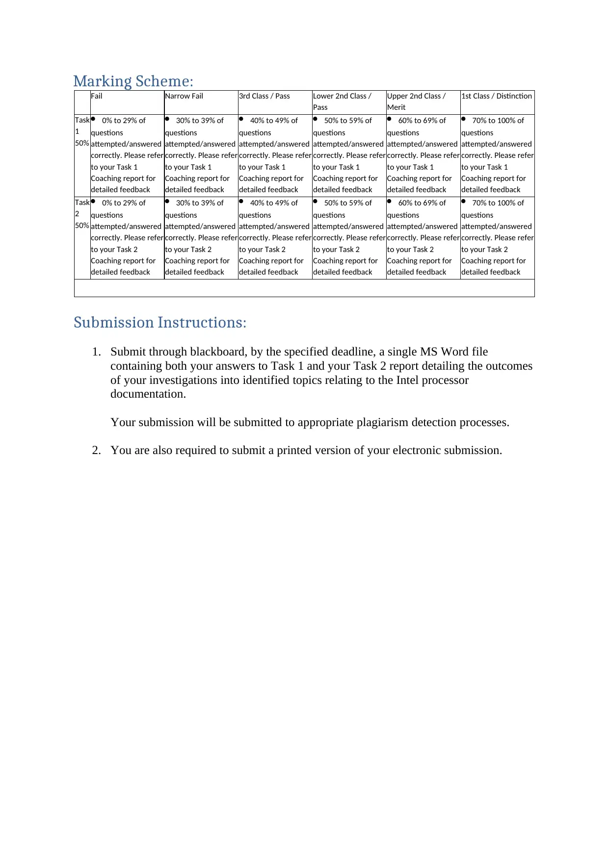
Marking Scheme:
Fail Narrow Fail 3rd Class / Pass Lower 2nd Class /
Pass
Upper 2nd Class /
Merit
1st Class / Distinction
Task
1
50%
0% to 29% of
questions
attempted/answered
correctly. Please refer
to your Task 1
Coaching report for
detailed feedback
30% to 39% of
questions
attempted/answered
correctly. Please refer
to your Task 1
Coaching report for
detailed feedback
40% to 49% of
questions
attempted/answered
correctly. Please refer
to your Task 1
Coaching report for
detailed feedback
50% to 59% of
questions
attempted/answered
correctly. Please refer
to your Task 1
Coaching report for
detailed feedback
60% to 69% of
questions
attempted/answered
correctly. Please refer
to your Task 1
Coaching report for
detailed feedback
70% to 100% of
questions
attempted/answered
correctly. Please refer
to your Task 1
Coaching report for
detailed feedback
Task
2
50%
0% to 29% of
questions
attempted/answered
correctly. Please refer
to your Task 2
Coaching report for
detailed feedback
30% to 39% of
questions
attempted/answered
correctly. Please refer
to your Task 2
Coaching report for
detailed feedback
40% to 49% of
questions
attempted/answered
correctly. Please refer
to your Task 2
Coaching report for
detailed feedback
50% to 59% of
questions
attempted/answered
correctly. Please refer
to your Task 2
Coaching report for
detailed feedback
60% to 69% of
questions
attempted/answered
correctly. Please refer
to your Task 2
Coaching report for
detailed feedback
70% to 100% of
questions
attempted/answered
correctly. Please refer
to your Task 2
Coaching report for
detailed feedback
Submission Instructions:
1. Submit through blackboard, by the specified deadline, a single MS Word file
containing both your answers to Task 1 and your Task 2 report detailing the outcomes
of your investigations into identified topics relating to the Intel processor
documentation.
Your submission will be submitted to appropriate plagiarism detection processes.
2. You are also required to submit a printed version of your electronic submission.
Document Page
Assessment Description:
Task 1
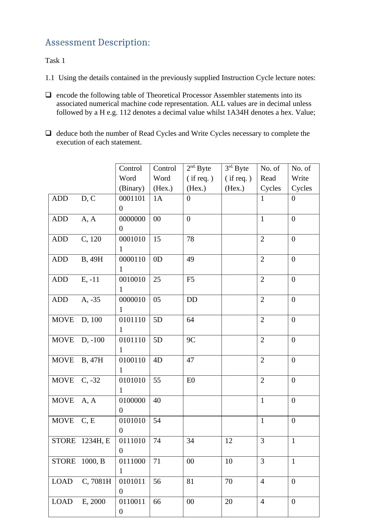
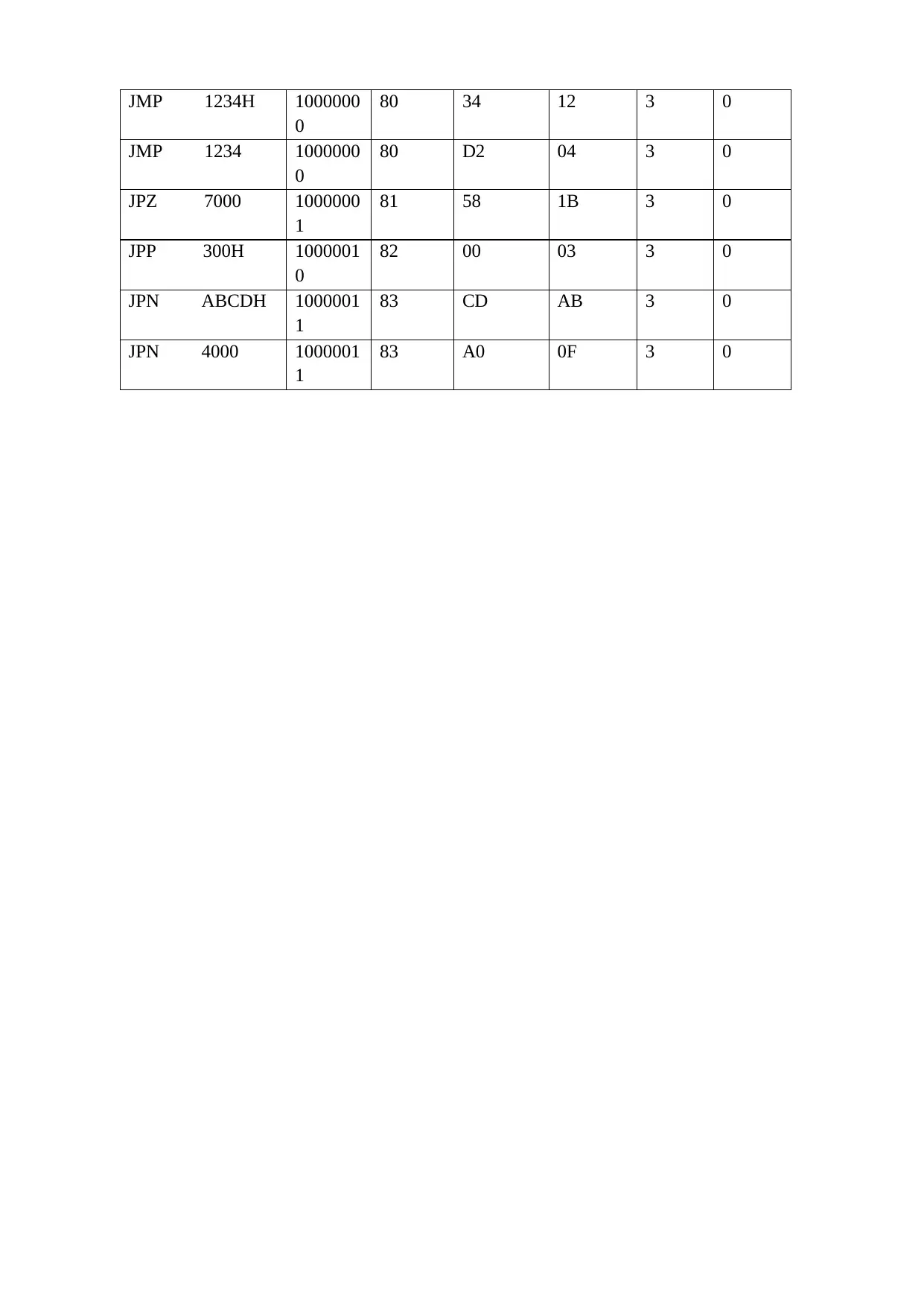
1.1 Using the details contained in the previously supplied Instruction Cycle lecture notes:
encode the following table of Theoretical Processor Assembler statements into its
associated numerical machine code representation. ALL values are in decimal unless
followed by a H e.g. 112 denotes a decimal value whilst 1A34H denotes a hex. Value;
deduce both the number of Read Cycles and Write Cycles necessary to complete the
execution of each statement.
Control
Word
(Binary)
Control
Word
(Hex.)
2nd. Byte
( if req. )
(Hex.)
3rd. Byte
( if req. )
(Hex.)
No. of
Read
Cycles
No. of
Write
Cycles
ADD D, C 0001101
0
1A 0 1 0
ADD A, A 0000000
0
00 0 1 0
ADD C, 120 0001010
1
15 78 2 0
ADD B, 49H 0000110
1
0D 49 2 0
ADD E, -11 0010010
1
25 F5 2 0
ADD A, -35 0000010
1
05 DD 2 0
MOVE D, 100 0101110
1
5D 64 2 0
MOVE D, -100 0101110
1
5D 9C 2 0
MOVE B, 47H 0100110
1
4D 47 2 0
MOVE C, -32 0101010
1
55 E0 2 0
MOVE A, A 0100000
0
40 1 0
MOVE C, E 0101010
0
54 1 0
STORE 1234H, E 0111010
0
74 34 12 3 1
STORE 1000, B 0111000
1
71 00 10 3 1
LOAD C, 7081H 0101011
0
56 81 70 4 0
LOAD E, 2000 0110011
0
66 00 20 4 0
Document Page
JMP 1234H 1000000
0
80 34 12 3 0
JMP 1234 1000000
0
80 D2 04 3 0
JPZ 7000 1000000
1
81 58 1B 3 0
JPP 300H 1000001
0
82 00 03 3 0
JPN ABCDH 1000001
1
83 CD AB 3 0
JPN 4000 1000001
1
83 A0 0F 3 0
tabler-icon-diamond-filled.svg

Secure Best Marks with AI Grader

Need help grading? Try our AI Grader for instant feedback on your assignments.
Document Page
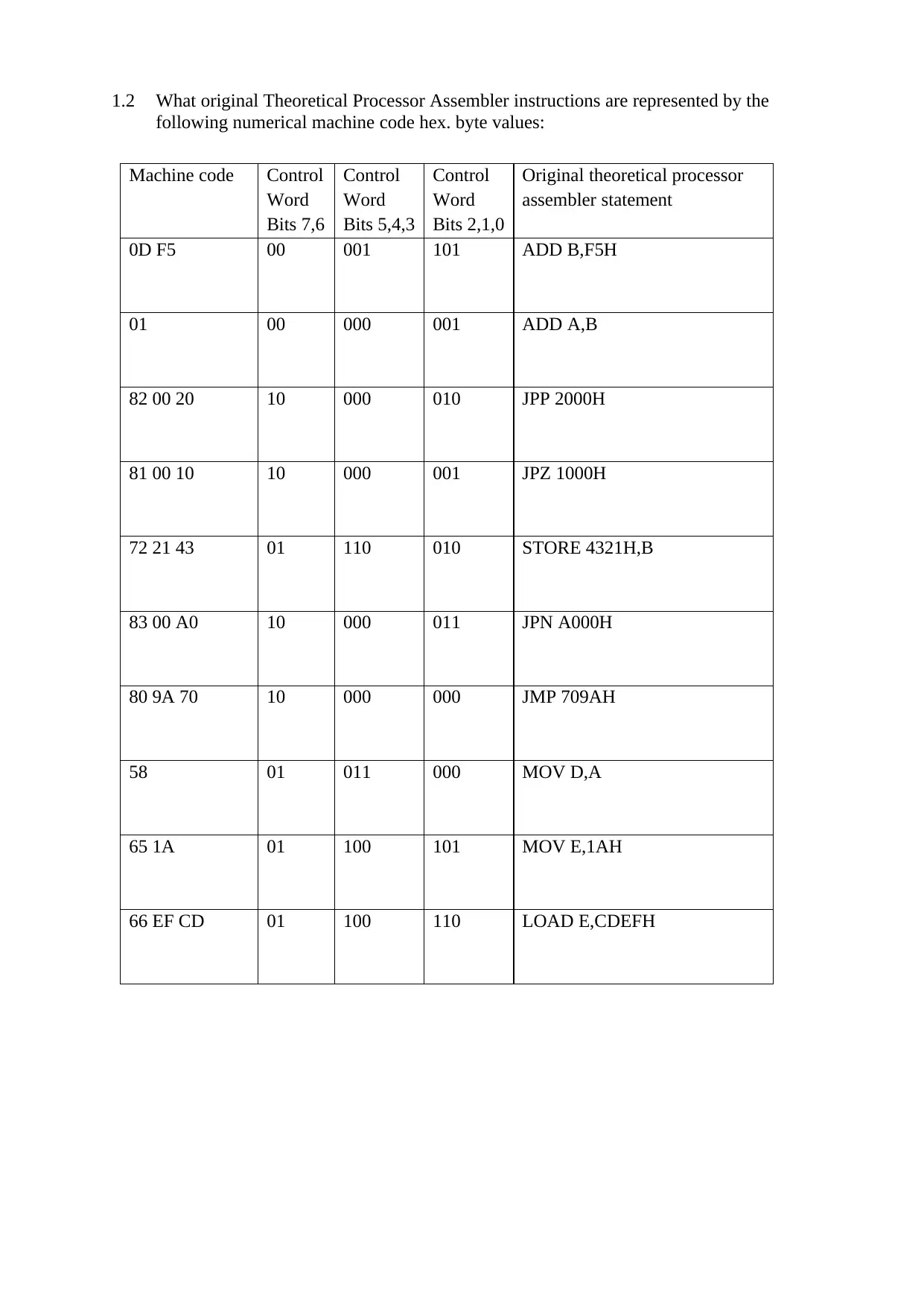
1.2 What original Theoretical Processor Assembler instructions are represented by the
following numerical machine code hex. byte values:
Machine code Control
Word
Bits 7,6
Control
Word
Bits 5,4,3
Control
Word
Bits 2,1,0
Original theoretical processor
assembler statement
0D F5 00 001 101 ADD B,F5H
01 00 000 001 ADD A,B
82 00 20 10 000 010 JPP 2000H
81 00 10 10 000 001 JPZ 1000H
72 21 43 01 110 010 STORE 4321H,B
83 00 A0 10 000 011 JPN A000H
80 9A 70 10 000 000 JMP 709AH
58 01 011 000 MOV D,A
65 1A 01 100 101 MOV E,1AH
66 EF CD 01 100 110 LOAD E,CDEFH
Document Page
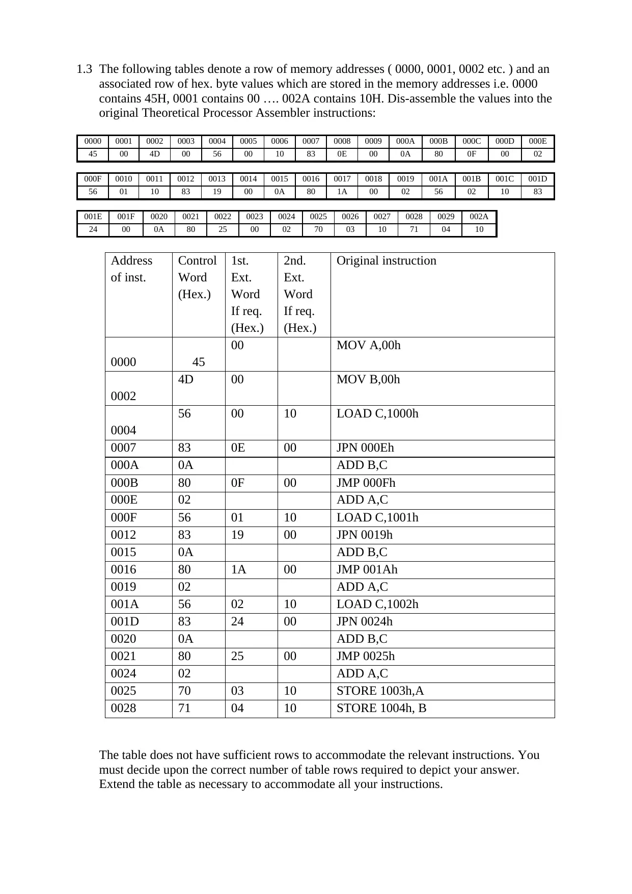
1.3 The following tables denote a row of memory addresses ( 0000, 0001, 0002 etc. ) and an
associated row of hex. byte values which are stored in the memory addresses i.e. 0000
contains 45H, 0001 contains 00 …. 002A contains 10H. Dis-assemble the values into the
original Theoretical Processor Assembler instructions:
0000 0001 0002 0003 0004 0005 0006 0007 0008 0009 000A 000B 000C 000D 000E
45 00 4D 00 56 00 10 83 0E 00 0A 80 0F 00 02
000F 0010 0011 0012 0013 0014 0015 0016 0017 0018 0019 001A 001B 001C 001D
56 01 10 83 19 00 0A 80 1A 00 02 56 02 10 83
001E 001F 0020 0021 0022 0023 0024 0025 0026 0027 0028 0029 002A
24 00 0A 80 25 00 02 70 03 10 71 04 10
Address
of inst.
Control
Word
(Hex.)
1st.
Ext.
Word
If req.
(Hex.)
2nd.
Ext.
Word
If req.
(Hex.)
Original instruction
0000 45
00 MOV A,00h
0002
4D 00 MOV B,00h
0004
56 00 10 LOAD C,1000h
0007 83 0E 00 JPN 000Eh
000A 0A ADD B,C
000B 80 0F 00 JMP 000Fh
000E 02 ADD A,C
000F 56 01 10 LOAD C,1001h
0012 83 19 00 JPN 0019h
0015 0A ADD B,C
0016 80 1A 00 JMP 001Ah
0019 02 ADD A,C
001A 56 02 10 LOAD C,1002h
001D 83 24 00 JPN 0024h
0020 0A ADD B,C
0021 80 25 00 JMP 0025h
0024 02 ADD A,C
0025 70 03 10 STORE 1003h,A
0028 71 04 10 STORE 1004h, B
The table does not have sufficient rows to accommodate the relevant instructions. You
must decide upon the correct number of table rows required to depict your answer.
Extend the table as necessary to accommodate all your instructions.
Document Page
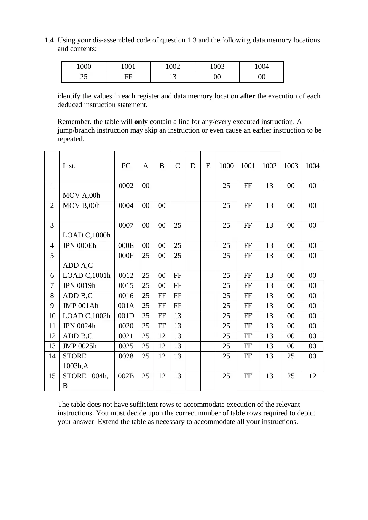
1.4 Using your dis-assembled code of question 1.3 and the following data memory locations
and contents:
1000 1001 1002 1003 1004
25 FF 13 00 00
identify the values in each register and data memory location after the execution of each
deduced instruction statement.
Remember, the table will only contain a line for any/every executed instruction. A
jump/branch instruction may skip an instruction or even cause an earlier instruction to be
repeated.
Inst. PC A B C D E 1000 1001 1002 1003 1004
1
MOV A,00h
0002 00 25 FF 13 00 00
2 MOV B,00h 0004 00 00 25 FF 13 00 00
3
LOAD C,1000h
0007 00 00 25 25 FF 13 00 00
4 JPN 000Eh 000E 00 00 25 25 FF 13 00 00
5
ADD A,C
000F 25 00 25 25 FF 13 00 00
6 LOAD C,1001h 0012 25 00 FF 25 FF 13 00 00
7 JPN 0019h 0015 25 00 FF 25 FF 13 00 00
8 ADD B,C 0016 25 FF FF 25 FF 13 00 00
9 JMP 001Ah 001A 25 FF FF 25 FF 13 00 00
10 LOAD C,1002h 001D 25 FF 13 25 FF 13 00 00
11 JPN 0024h 0020 25 FF 13 25 FF 13 00 00
12 ADD B,C 0021 25 12 13 25 FF 13 00 00
13 JMP 0025h 0025 25 12 13 25 FF 13 00 00
14 STORE
1003h,A
0028 25 12 13 25 FF 13 25 00
15 STORE 1004h,
B
002B 25 12 13 25 FF 13 25 12
The table does not have sufficient rows to accommodate execution of the relevant
instructions. You must decide upon the correct number of table rows required to depict
your answer. Extend the table as necessary to accommodate all your instructions.
tabler-icon-diamond-filled.svg

Paraphrase This Document

Need a fresh take? Get an instant paraphrase of this document with our AI Paraphraser
Document Page
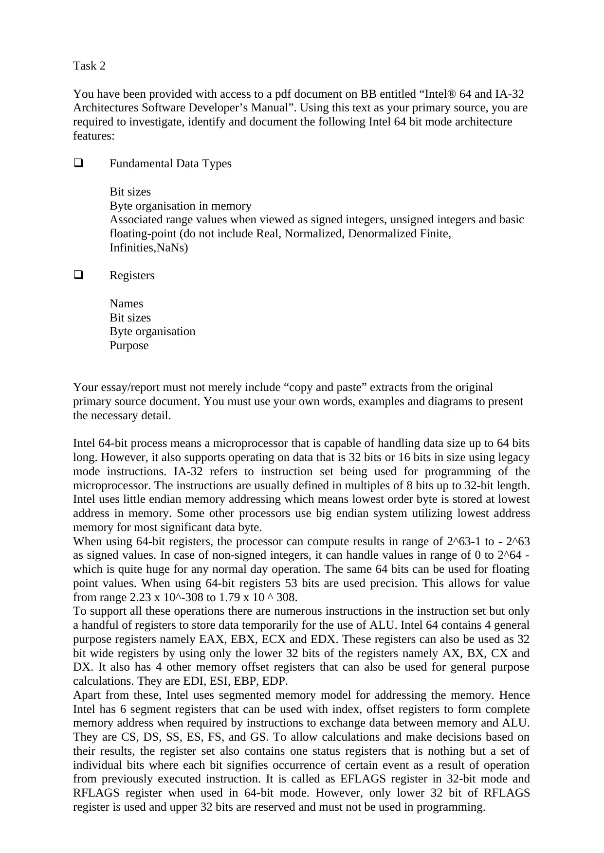
Task 2
You have been provided with access to a pdf document on BB entitled “Intel® 64 and IA-32
Architectures Software Developer’s Manual”. Using this text as your primary source, you are
required to investigate, identify and document the following Intel 64 bit mode architecture
features:
Fundamental Data Types
Bit sizes
Byte organisation in memory
Associated range values when viewed as signed integers, unsigned integers and basic
floating-point (do not include Real, Normalized, Denormalized Finite,
Infinities,NaNs)
Registers
Names
Bit sizes
Byte organisation
Purpose
Your essay/report must not merely include “copy and paste” extracts from the original
primary source document. You must use your own words, examples and diagrams to present
the necessary detail.
Intel 64-bit process means a microprocessor that is capable of handling data size up to 64 bits
long. However, it also supports operating on data that is 32 bits or 16 bits in size using legacy
mode instructions. IA-32 refers to instruction set being used for programming of the
microprocessor. The instructions are usually defined in multiples of 8 bits up to 32-bit length.
Intel uses little endian memory addressing which means lowest order byte is stored at lowest
address in memory. Some other processors use big endian system utilizing lowest address
memory for most significant data byte.
When using 64-bit registers, the processor can compute results in range of 2^63-1 to - 2^63
as signed values. In case of non-signed integers, it can handle values in range of 0 to 2^64 -
which is quite huge for any normal day operation. The same 64 bits can be used for floating
point values. When using 64-bit registers 53 bits are used precision. This allows for value
from range 2.23 x 10^-308 to 1.79 x 10 ^ 308.
To support all these operations there are numerous instructions in the instruction set but only
a handful of registers to store data temporarily for the use of ALU. Intel 64 contains 4 general
purpose registers namely EAX, EBX, ECX and EDX. These registers can also be used as 32
bit wide registers by using only the lower 32 bits of the registers namely AX, BX, CX and
DX. It also has 4 other memory offset registers that can also be used for general purpose
calculations. They are EDI, ESI, EBP, EDP.
Apart from these, Intel uses segmented memory model for addressing the memory. Hence
Intel has 6 segment registers that can be used with index, offset registers to form complete
memory address when required by instructions to exchange data between memory and ALU.
They are CS, DS, SS, ES, FS, and GS. To allow calculations and make decisions based on
their results, the register set also contains one status registers that is nothing but a set of
individual bits where each bit signifies occurrence of certain event as a result of operation
from previously executed instruction. It is called as EFLAGS register in 32-bit mode and
RFLAGS register when used in 64-bit mode. However, only lower 32 bit of RFLAGS
register is used and upper 32 bits are reserved and must not be used in programming.
Document Page
To make sure program executes in correct sequence, the processor also maintains a
instruction pointer register. This is again 64-bit register that can point to next memory
location where next instruction is located. It is named as PC or Program Counter.
Task 3
During the weeks following the submission deadline and prior to the feedback deadline you
will be required to undertake two in-class open-book multiple-choice-single-answer online
assessments, one for Task 1 and another for Task 2. The purpose of the assessment questions
will be to:
mark various aspects/answers of your task 1 work.
present/ask new unseen questions on the material covered by task 2.
During the online assessments you will be permitted to refer to your assignment text to
answer the presented questions. This is the only open-book source material you will be
permitted to make reference to during the online assessments.
No further web searches will be permitted. No calculators will be permitted.
You will be required to return your assignment text upon completing each of the two on-line
assessments.
You will only be allowed to attempt the online assessments if you have previously submitted
material to reference.
The final mark will only be awarded against previously submitted material received by the
appropriate deadline.
chevron_up_icon
1 out of 9
circle_padding
hide_on_mobile
zoom_out_icon
[object Object]

Your All-in-One AI-Powered Toolkit for Academic Success.

Available 24*7 on WhatsApp / Email

[object Object]