logo

FEA Analysis of a Plane Truss

This resit coursework consists of two sections: Mathematics and Finite Element Analysis (FEA). The Maths part is worth 25% of the mark, and the finite element part is worth 75% of the mark. BOTH PARTS NEED TO BE SOLVED

4 Pages2065 Words287 Views
   

Added on  2022-11-29

About This Document

This article discusses the Finite Element Analysis (FEA) of a plane truss using ANSYS software. It covers the theoretical calculations, steps involved in the analysis, and the results obtained. The accuracy and effectiveness of FEM in solving structural problems are also explored.

FEA Analysis of a Plane Truss

This resit coursework consists of two sections: Mathematics and Finite Element Analysis (FEA). The Maths part is worth 25% of the mark, and the finite element part is worth 75% of the mark. BOTH PARTS NEED TO BE SOLVED

   Added on 2022-11-29

ShareRelated Documents
FEA analysis of a Plane Truss
Mujib Mustafa
ID: 19
Abstract—FEM is a numerical technique used to solve partial
differential equations arising in analysis of engineering problems.
FEA packages like ANSYS use this numerical technique to solve
wide variety of problems. In this study ANSYS is used to solve a
simple problem in structural analysis. A plane truss in modelled,
meshed and solved, using static structural solver, for the given
constrains. The linearity in geometry and deformation of truss
is truly captured by ANSYS using simple link elements, which
resulted in exact solution to the problem.
Index Terms—FEM, ANSYS, numerical, truss, link, deforma-
tion
I. INTRODUCTION
The Finite Element Method (FEM) is one of the many nu-
merical techniques used to solve differential equations arising
in mathematical models of engineering problems. Numeri-
cal methods have evolved over time providing solutions to
complex problems in nature and their accuracy and ability to
deal with more and more complex phenomenon has improved
drastically in recent times owing the tremendous increase in
processing powers of computers (Seshu 2010).
FEM packages are commercially available both as proprietary
software (eg. ANSYS, ABAQUS, COMSOL etc.) and open
source codes (eg. CalculiX, FreeFEM++ etc.).
The aim of this study is to use a FEA (finite element analysis)
package to solve a simple problem in structural analysis. A
plane truss with simple loading and support(s) is analyzed us-
ing ANSYS software (ver. 19.2). ANSYS includes a Mechan-
ical APDL package which is suitable for structural analysis of
wide variety of problems. The underlying process of ANSYS
Mechanical to solve a problem in structure is very similar to
the general approach of FEM. The geometry is divided into
simple elements which are connected at nodes. Displacement
at nodes is determined using a simple force- displacement
relation: [K][x] = f , where [K] is called stiffness matrix,
it contains geometric and material properties of the setup. The
solution at the node is interpolated throughout the domain
using shape function (Seshu 2010).
In this report, the given problem is first solved theoretically
using equilibrium principles of statics. These calculations are
presented in section II. In the next section, III, FEA analysis
of the problem is described. Results form the analysis are
presented in section IV along with comparisons to theoretical
results. Conclusion of the study is presented in the final
section, V.
II. THEORETICAL CALCULATIONS
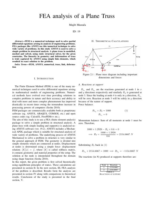
Figure 2.1 : Plane truss diagram including important
dimensions and forces
A. Reactions at support
R1x and R1y are the reactions generated at node 1 in x
and y directions respectively and similarly R3 is generated at
node 3. Since the loading at node 4 is only in y direction, R1x
will be zero. Reaction at node 3 will be solely in y direction
because of the nature of support.
Force balance:
R1y + R3 = 1000 (1)
R1x = 0
Momentum balance: Sum of all moments at node 1 must be
zero. Therefore,
1000 × 1.2928 R3 × 0.6 = 0
= R3 = 1000 × 1.2928
0.6 = 2154.6667 N
Substituting R3 back in (1)
R1y + 2154.6667 = 1000 = R1y = 1154.6667 N
The reactions (in N) produced at supports therefore are:
Node Reaction
1 -1154.6667
2 2154.6667
TABLE I
REACTIONS AT SUPPORT
FEA Analysis of a Plane Truss_1
B. Forces in the elements of the truss
Using method of joints (Plesha 2014) to evaluate forces in
all elements of the truss. Force balance principle is applied
to each node to help determine the unknown forces in the
elements.
Forces away from joints (nodes) are considered tensile and
forces towards joints are considered compressive.
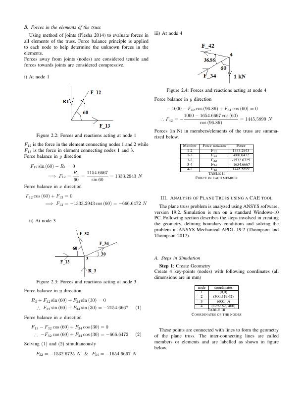
i) At node 1
Figure 2.2: Forces and reactions acting at node 1
F12 is the force in the element connecting nodes 1 and 2 while
F13 is the force in element connecting nodes 1 and 3.
Force balance in y direction
F12 sin (60) R1 = 0
= F12 = R1
60 = 1154.6667
sin 60 = 1333.2943 N
Force balance in x direction
F12 cos (60) + F13 = 0
= F13 = 1333.2943 cos (60) = 666.6472 N
ii) At node 3
Figure 2.3: Forces and reactions acting at node 3
Force balance in y direction
R3 + F32 sin (60) + F34 sin (30) = 0
F32 sin (60) + F34 sin (30) = 2154.6667 (1)
Force balance in x direction
F13 F32 cos (60) + F34 cos (30) = 0
F32 cos (60) + F34 cos (30) = 666.6472 (2)
Solving (1) and (2) simultaneously
F32 = 1532.6725 N & F34 = 1654.6667 N
iii) At node 4
Figure 2.4: Forces and reactions acting at node 4
Force balance in y direction
1000 F42 cos (96.86) + F34 cos (60) = 0
F42 = 1000 1654.6667 cos (60)
cos (96.86) = 1445.5899 N
Forces (in N) in members/elements of the truss are summa-
rized below.
Member Force notation Force
1-2 F12 1333.2943
1-3 F13 -666.6472
3-2 F32 -1532.6725
3-4 F34 -1654.6667
4-2 F42 1445.5899
TABLE II
FORCE IN EACH MEMBER
III. ANALYSIS OF PLANE TRUSS USING A CAE TOOL
The plane truss problem is analyzed using ANSYS software,
version 19.2. Simulation is run on a standard Windows-10
PC. Following section describes the steps involved in creating
the geometry, defining boundary conditions and solving the
problem in ANSYS Mechanical APDL 19.2 (Thompson and
Thompson 2017).
A. Steps in Simulation
Step 1: Create Geometry
Create 4 key-points (nodes) with following coordinates (all
dimensions are in mm)
node coordinates
1 (0,0)
2 (300,519.62)
3 (600, 0)
4 (1292.82, 400)
TABLE III
COORDINATES OF THE NODES
These points are connected with lines to form the geometry
of the plane truss. The inter-connecting lines are called
members or elements and are labelled as shown in figure
below.
FEA Analysis of a Plane Truss_2

End of preview

Want to access all the pages? Upload your documents or become a member.

Related Documents
Solution for Nodal Displacements and Rotations in Frame Structure
|14
|1096
|98

Finite Element Method (Part 1) EG55M1 Assignment 1 - University of Aberdeen
|11
|1996
|124