Gas Turbine Combustion Systems & Technology
VerifiedAdded on 2020/04/29
|9
|4230
|222
AI Summary
This assignment delves into the intricacies of gas turbine combustion systems, encompassing their design principles, materials used, and environmental impact. It explores topics such as lean-burn combustion, plasma assistance, dual fuel systems, and emissions reduction technologies. The provided sources offer insights into research advancements, practical applications, and future trends in gas turbine technology.
Contribute Materials
Your contribution can guide someone’s learning journey. Share your
documents today.
Gas Turbine Engine Combustion Systems
Introduction
The gas turbine engine is an internal combustion engine, which employs the use of gas as
the working fluid use in turning the turbine. The gas turbine engine has several parts which
include a compressor, combustion chamber and a turbine (Benson, 2008). The combustion
system is critical since it is able to generate the required power to move the other systems of a
machine. Since the innovation of the gas turbine engine, different developments have taken place
on the combustion systems in order to enhance the efficiency and operation of the engine. The
burning system of the fuel is important in enhancing the operation and efficiency of the entire
engine. At the combustion chamber, different materials are mixed to enhance the combustion
process. The materials are used to burn the fuel and increase the power output of the engine. Key
developments have taken place since the invention of gas engine in the 19th century. The
combustion systems in the gas turbine engines play a key role in enhancing the power output and
generation in the systems (Flack, 2009). Different industries rely on the combustion system of
the engine in order to get their required energy. For the turbo machinery, the gas turbine is a key
item to provide energy to the industries such as power generation, oil and gas, processing plants,
aviation industry, domestic and industrials sectors as well.
Investigation of combustion system
First, the idea of a gas turbine engine was developed by Leonardo da Vinci and then
detailed by John Wilkins in 1648 (Henderson, and Blazowski, 2008). Since then the combustion
area has been identified to be critical and has undergone different developments to meet the
market specifications. The engine shaft relies on the combustion system in order to move at the
required speed. The shaft will move according to the power which the combustion chamber is
able to provide. This makes the combustion chamber a key area of concentration for many when
trying to improve the efficiency of machinery. The combustion system requires a cooling system
in order to control the heating effect (Tamarin, 2012). These systems are able to ensure that the
system is able to operate at normal temperature in order to achieve the efficiency. Much heat is
able to slow down the machinery systems operations and therefore able to prevent the perfect
functioning and attaining of the required goals. The combustion system is a key area where the
combustion of fuel is able to take place in an engine.
At this system, air and fuels are mixed and heated at high pressure, which is constant.
The mixture is then allowed to flow to the next engine compartment, which are the turbine vanes
(Mattingly, Heiser, and Pratt, 2012). Key developments of the of the turbine engine have been
taken place in order to enhance a constant and maintain constant combustion rate even with
variation of high air flow rates. This ensures that the power output will be constant at any given
moment when the engine is running in relation to the amount of mixture is being burnt. The
combustion system designs have been modified in these developments. The different design
aspects aim to achieve a proper control of the mixtures in the system. The mixing pattern on
what has to be fed first and what will enter last ensures that the efficiency and maximum burning
of the elements is achieved. The latest procedure of mixing allows the entry of ignition air, then
fuel and then more air, which is used to enhance complete combustion, is allowed in the system.
This system was achieved from an earlier development where the turbine engine combustion
system has only one chamber which was able to accommodate all these elements at the same
time (Goyne et al., 2010). The earlier system, known as the type combustor was able to promote
Secure Best Marks with AI Grader
Need help grading? Try our AI Grader for instant feedback on your assignments.
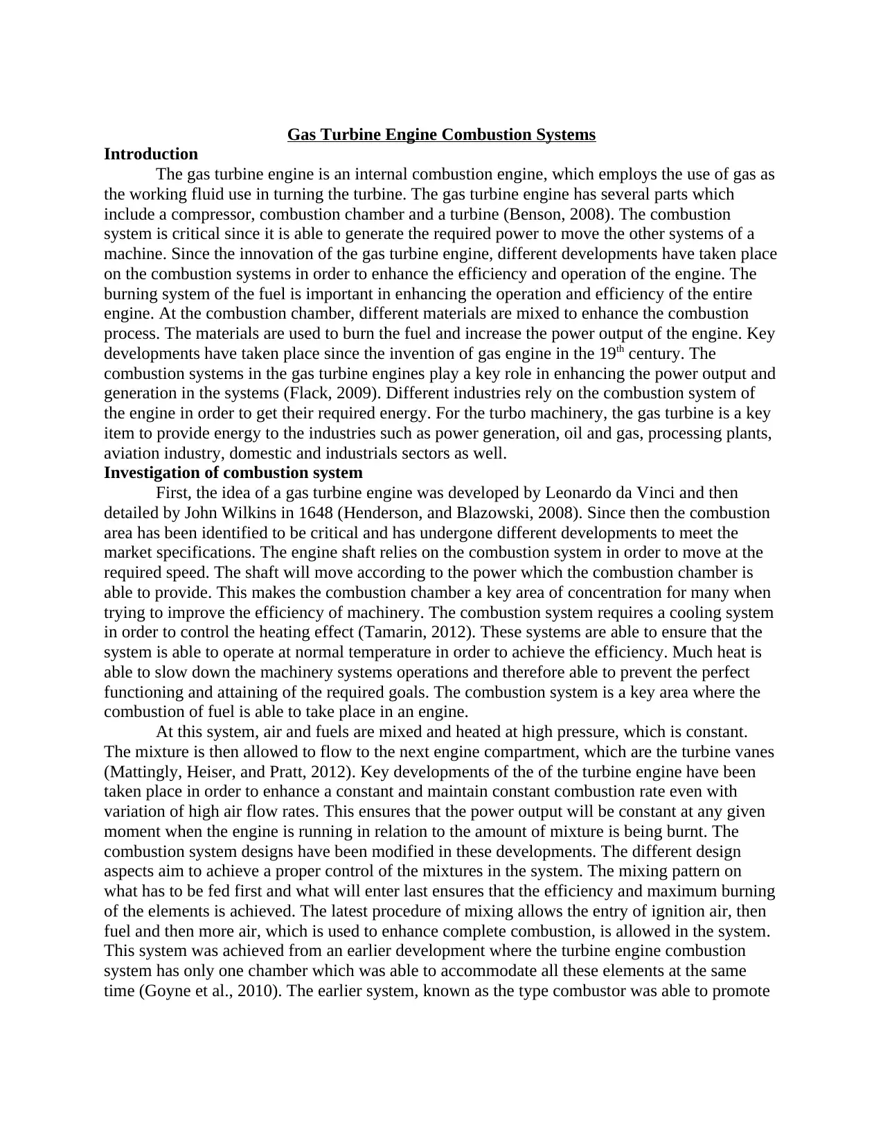
incomplete combustion since air and furl were being burnt at the same time. Of late, many types
of combustion systems have been developed with different configurations.
Annular, afterburners and cannular, also known as can-annular turbo-annular are some of
the key combustion systems which are used in the gas turbine engines recently (Waltrup et al.,
2012). The developments are meant to achieve some key aspects such as fuel efficiency,
reduction of the emission levels to the environment and enhancing the transient response. The
transient response is the response to the change of conditions such as the fuel flow and the speed
at which air enters the combustion systems. The development to enhance these factors ensures
that the power output from the combustion chamber can be control and prevent abnormal
variations for the moving machines.
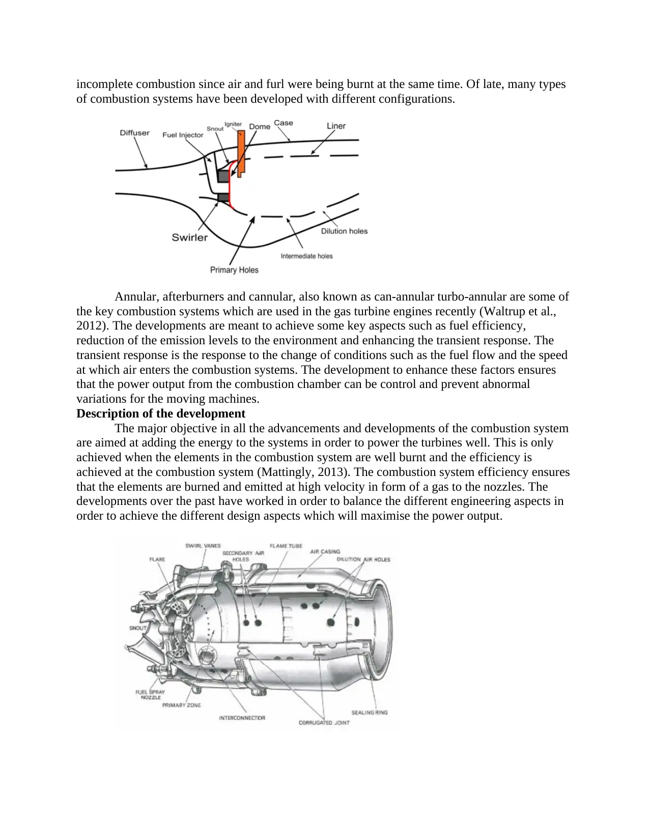
Description of the development
The major objective in all the advancements and developments of the combustion system
are aimed at adding the energy to the systems in order to power the turbines well. This is only
achieved when the elements in the combustion system are well burnt and the efficiency is
achieved at the combustion system (Mattingly, 2013). The combustion system efficiency ensures
that the elements are burned and emitted at high velocity in form of a gas to the nozzles. The
developments over the past have worked in order to balance the different engineering aspects in
order to achieve the different design aspects which will maximise the power output.
of combustion systems have been developed with different configurations.
Annular, afterburners and cannular, also known as can-annular turbo-annular are some of
the key combustion systems which are used in the gas turbine engines recently (Waltrup et al.,
2012). The developments are meant to achieve some key aspects such as fuel efficiency,
reduction of the emission levels to the environment and enhancing the transient response. The
transient response is the response to the change of conditions such as the fuel flow and the speed
at which air enters the combustion systems. The development to enhance these factors ensures
that the power output from the combustion chamber can be control and prevent abnormal
variations for the moving machines.
Description of the development
The major objective in all the advancements and developments of the combustion system
are aimed at adding the energy to the systems in order to power the turbines well. This is only
achieved when the elements in the combustion system are well burnt and the efficiency is
achieved at the combustion system (Mattingly, 2013). The combustion system efficiency ensures
that the elements are burned and emitted at high velocity in form of a gas to the nozzles. The
developments over the past have worked in order to balance the different engineering aspects in
order to achieve the different design aspects which will maximise the power output.
The combustion system has experienced developments in different areas. Some of the
key areas which have experienced the developments include the emissions, operating ranges and
the durability of the system. On these key areas, different components have been varied in order
to meet some key aspects of the designs which were limiting. The advances on the gas turbine
engines combustion systems are able to date as long as 1950s (Sturgess et al., 2009). In each
development in these aspects, the design looks to address some key cons which are experienced
in order to enhance the efficiency in power output or even other factors. Since the combustion
system has different elements such as the casing, diffuser, fuel injector, dome, liner, dilution
holes and primary holes, swirler among other parts, these components are changed in terms of
design to achieve the required aspects during the developments. The developments have played a
critical role in enhancing the operations of the combustion systems in these engines.
One of the key developments on the gas engine combustion system in the 1950s was to
enhance the control of the emissions from the engine. Reduction of the smoke emission by the
gas engine has been one of the major goals (Matveev, and Serbin, 2012). The combustion
process is able to lead to the production of the smoke, which is mostly an indicator of incomplete
combustion of the fuel. The developments of enhancing the reduction of smoke emissions
specifically were carried out in the 1950s. Smoke as seen, result from the incomplete combustion
of the fuel. The main controller of combustion process is the injection of the air within the
combustion chamber in order to enhance complete combustion of the fuel. Therefore, when it
was noted that initial combustion system in the gas turbine engine did not support complete
combustion; inlets were developed to allow injection of air at different stages. Through the
injection of air at the initial stage and the final stage is able to control the combustion process
and making sure that all the fuel is able to burn completely (Matveev, et al., 2013). The injection
of air at different stages ensures even mixing of the fuel which was not achieved at the earlier
engines. This ensures that the fuel will burn fully and control the smoke emission to the
environment. In addition, the control of the smoke is also achieved through the kind of fuel
injector used. The development of the modern fuel injector such as the airblast fuel injectors has
been able to control the smoke emissions from the gas turbine engines. The fuel injectors
developed are able to atomize the fuel and therefore able to eliminate the local pockets which
result to high fuel concentration causing smoke. These allow proper burning of the fuel and
ensuring that the smoke is controlled to the minimum levels. These types of injectors enhance the
burning of the fuel completely and therefore smokeless.
The fuel injector is a key part of the combustion systems in the gas turbine engine.
Different types of injectors have been developed in order to enhance environmental friendliness
of the engines (Jung and Becker, 2010). The control of smoke emissions has led to the
development of the different fuel injectors for this engine. Some of the key injectors which have
been used in this type of engine include the pressure atomizing injector, air blast injector,
vaporizing and premix injectors. The initial fuel injector used for this engine was the pressure
vaporizing injector. Although very simple to use, this injector was able to lead to incomplete
combustion of the fuel and therefore increasing the smoke emission to the environment. The
increased pollution from the use of this injector led to the development and use of other injectors
which enhance complete burning of the fuel to control the pollutants (Eckardt and Rufli, 2010).
The air blast injector was developed and was the first kind of smokeless injector to be used
within the combustion system. This injector required less air pressure to atomize the fuel than the
initial fuel injector.
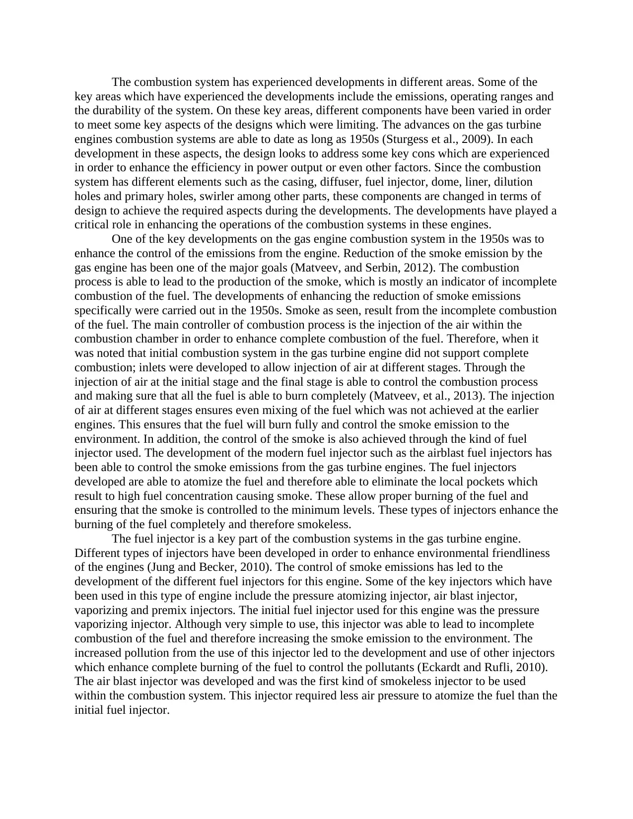
The durability of the combustion system is key for any engine to keep the machine
working. The air blast injector allowed the mixing and burning of fuel and primary air at the
same compartment. This was able to compromise the durability of the liner for the combustion
system (Serbin, Matveev, and Mostipanenko, 2011). The durability issue led to the development
of the vaporizing injector, which allowed the fuel-air mixture to travel through a tube within the
combustion system. The heat from the combustion system is transferred to the mixture and
therefore vaporizing it before the combustion of the mixture. This reduces the thermal radiations
which are used in the combustion of the mixture and therefore increasing the durability of the
whole combustion system through protection of the liner. Nevertheless, this injector is not able to
support proper mixing of the fuel and air within the tube. In order to address this shortcoming,
the premix injector was developed (Lefebvre and Ballal, 2010) be enhanced. The mixing in these
injectors is able to enhance the liner durability and therefore enhancing both emission control
and durability factors of the combustion system of the engine.
Another area which the gas turbine engines have experienced developments is the dome
and swirler parts. These are main areas where the primary air is able to enter through as it enters
the combustion system (Welch and Igoe, 2015 ). The main role of the swirler and dome is to
create turbulence in the air flow in order to ensure proper and uniform mixing with the fuel.
Bluff body domes where used earlier instead of the swirlers. The earlier domes consisted of
simple places which were used to create the turbulence and mix air and fuel. The developments
on this part led to the introduction of the swirlers. The swirlers are able to create a local low
pressure zone. The low pressure zone is able to recirculate the mixing products and therefore
able to create high turbulence. The design of the dome and swirler are done such that they can be
able to withstand the high pressure and turbulence created (Koff, 2014). The strength of the
materials used is created to ensure that the durability of the combustion system is achieved. The
development in this section of the system was key to ensure that the controls of emission which
pollute the environment are minimized. The elements are seen that they are able to enhance
proper mixing of the fuel and the air to ensure complete combustion of the mixture within the
combustion system.
Secure Best Marks with AI Grader
Need help grading? Try our AI Grader for instant feedback on your assignments.
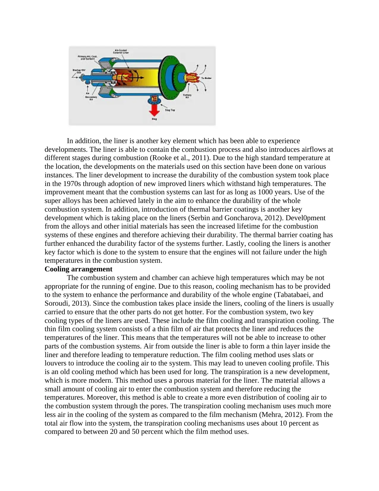
In addition, the liner is another key element which has been able to experience
developments. The liner is able to contain the combustion process and also introduces airflows at
different stages during combustion (Rooke et al., 2011). Due to the high standard temperature at
the location, the developments on the materials used on this section have been done on various
instances. The liner development to increase the durability of the combustion system took place
in the 1970s through adoption of new improved liners which withstand high temperatures. The
improvement meant that the combustion systems can last for as long as 1000 years. Use of the
super alloys has been achieved lately in the aim to enhance the durability of the whole
combustion system. In addition, introduction of thermal barrier coatings is another key
development which is taking place on the liners (Serbin and Goncharova, 2012). Devel0pment
from the alloys and other initial materials has seen the increased lifetime for the combustion
systems of these engines and therefore achieving their durability. The thermal barrier coating has
further enhanced the durability factor of the systems further. Lastly, cooling the liners is another
key factor which is done to the system to ensure that the engines will not failure under the high
temperatures in the combustion system.
Cooling arrangement
The combustion system and chamber can achieve high temperatures which may be not
appropriate for the running of engine. Due to this reason, cooling mechanism has to be provided
to the system to enhance the performance and durability of the whole engine (Tabatabaei, and
Soroudi, 2013). Since the combustion takes place inside the liners, cooling of the liners is usually
carried to ensure that the other parts do not get hotter. For the combustion system, two key
cooling types of the liners are used. These include the film cooling and transpiration cooling. The
thin film cooling system consists of a thin film of air that protects the liner and reduces the
temperatures of the liner. This means that the temperatures will not be able to increase to other
parts of the combustion systems. Air from outside the liner is able to form a thin layer inside the
liner and therefore leading to temperature reduction. The film cooling method uses slats or
louvers to introduce the cooling air to the system. This may lead to uneven cooling profile. This
is an old cooling method which has been used for long. The transpiration is a new development,
which is more modern. This method uses a porous material for the liner. The material allows a
small amount of cooling air to enter the combustion system and therefore reducing the
temperatures. Moreover, this method is able to create a more even distribution of cooling air to
the combustion system through the pores. The transpiration cooling mechanism uses much more
less air in the cooling of the system as compared to the film mechanism (Mehra, 2012). From the
total air flow into the system, the transpiration cooling mechanisms uses about 10 percent as
compared to between 20 and 50 percent which the film method uses.
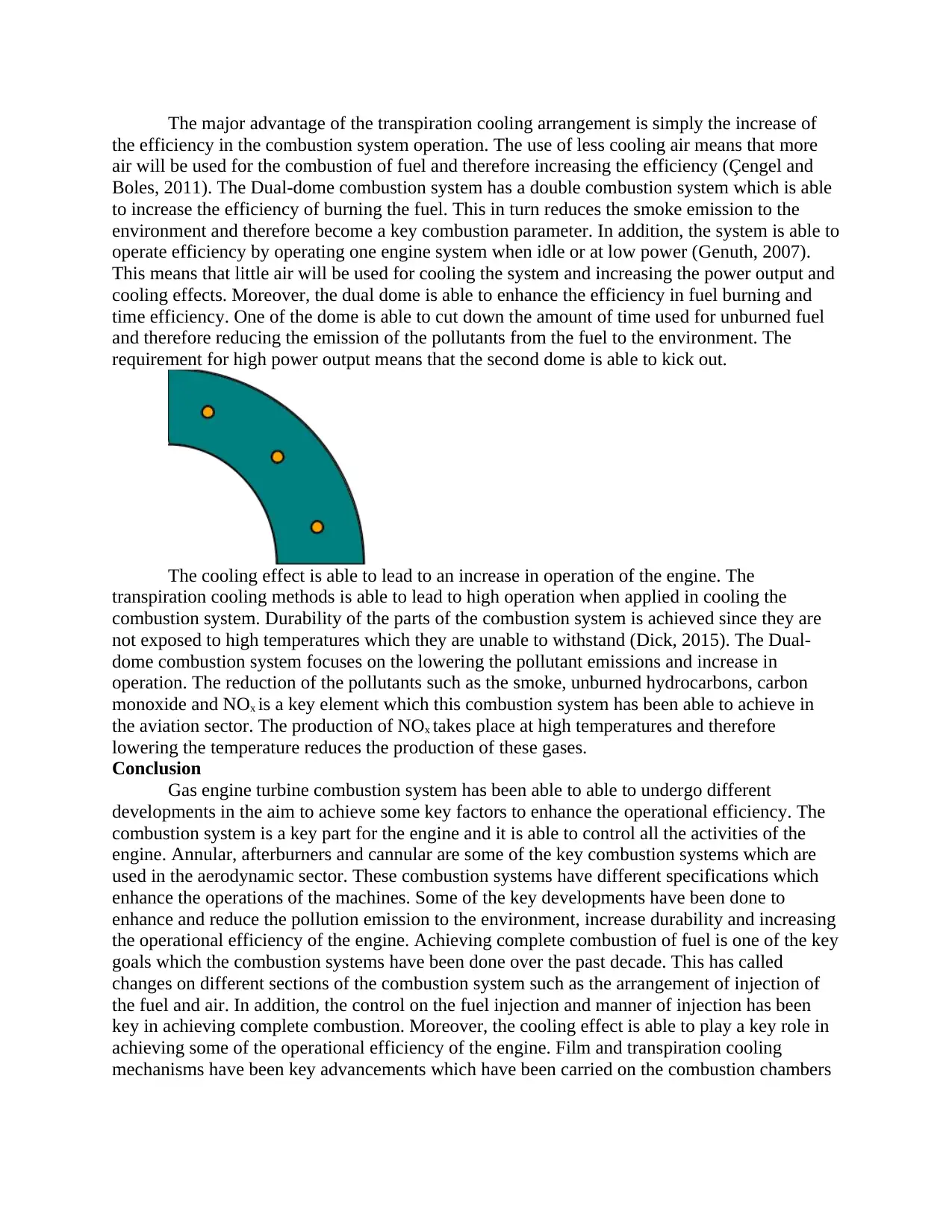
The major advantage of the transpiration cooling arrangement is simply the increase of
the efficiency in the combustion system operation. The use of less cooling air means that more
air will be used for the combustion of fuel and therefore increasing the efficiency (Çengel and
Boles, 2011). The Dual-dome combustion system has a double combustion system which is able
to increase the efficiency of burning the fuel. This in turn reduces the smoke emission to the
environment and therefore become a key combustion parameter. In addition, the system is able to
operate efficiency by operating one engine system when idle or at low power (Genuth, 2007).
This means that little air will be used for cooling the system and increasing the power output and
cooling effects. Moreover, the dual dome is able to enhance the efficiency in fuel burning and
time efficiency. One of the dome is able to cut down the amount of time used for unburned fuel
and therefore reducing the emission of the pollutants from the fuel to the environment. The
requirement for high power output means that the second dome is able to kick out.
The cooling effect is able to lead to an increase in operation of the engine. The
transpiration cooling methods is able to lead to high operation when applied in cooling the
combustion system. Durability of the parts of the combustion system is achieved since they are
not exposed to high temperatures which they are unable to withstand (Dick, 2015). The Dual-
dome combustion system focuses on the lowering the pollutant emissions and increase in
operation. The reduction of the pollutants such as the smoke, unburned hydrocarbons, carbon
monoxide and NOx is a key element which this combustion system has been able to achieve in
the aviation sector. The production of NOx takes place at high temperatures and therefore
lowering the temperature reduces the production of these gases.
Conclusion
Gas engine turbine combustion system has been able to able to undergo different
developments in the aim to achieve some key factors to enhance the operational efficiency. The
combustion system is a key part for the engine and it is able to control all the activities of the
engine. Annular, afterburners and cannular are some of the key combustion systems which are
used in the aerodynamic sector. These combustion systems have different specifications which
enhance the operations of the machines. Some of the key developments have been done to
enhance and reduce the pollution emission to the environment, increase durability and increasing
the operational efficiency of the engine. Achieving complete combustion of fuel is one of the key
goals which the combustion systems have been done over the past decade. This has called
changes on different sections of the combustion system such as the arrangement of injection of
the fuel and air. In addition, the control on the fuel injection and manner of injection has been
key in achieving complete combustion. Moreover, the cooling effect is able to play a key role in
achieving some of the operational efficiency of the engine. Film and transpiration cooling
mechanisms have been key advancements which have been carried on the combustion chambers

of the gas turbine engine. Lowering the temperature on the liner has been able to effect different
parameters of the engine.
parameters of the engine.
Paraphrase This Document
Need a fresh take? Get an instant paraphrase of this document with our AI Paraphraser
References
Benson, T. 2008 Combustor-Burner. NASA Glenn Research Center. Last Updated 11 Jul 2008.
Çengel, Y. A., and Boles, M. A. 2011."9-8." Thermodynamics: An Engineering Approach. 7th
ed. New York: McGraw-Hill, 510. Print.
Dick, E. 2015. "Thrust Gas Turbines". Fundamentals of Turbomachines. Dordrecht:
Springer.109.
Eckardt, D. and Rufli, P. 2010. "Advanced Gas Turbine Technology - ABB/ BBC Historical
Firsts", ASME J. Eng. Gas Turb. Power, p. 124, 542-549
Flack, R. D. 2009. "Chapter 9: Combustors and Afterburners". Fundamentals of Jet Propulsion
with Applications. Cambridge Aerospace Series. New York, NY: Cambridge University Press.
Genuth, I. 2007. "Engine on a Chip". The Future of Things.
Goyne, C. P., Hall, C. D., O'Brian, W. F., and Schetz, J. A. 2010. The Hy-V Scramjet Flight
Experiment. 14th AIAA/AHI Space Planes and Hypersonic Systems and Technologies
Conference. AIAA 2006-7901. Nov 2006.
Henderson, R. E.; and Blazowski, W. S. 2008. "Chapter 2: Turbopropulsion Combustion
Technology". In Oates, Gordon C. Aircraft Propulsion Systems Technology and Design. AIAA
Education Series. Washington, DC: American Institute of Aeronautics and Astronautics.
Jung, H. J. and Becker, E. R. 2010. “Emission control for gas turbines,” Platinum Metals
Review, vol. 31, no. 4, pp. 162–170.
Koff, B. L. 2014. Gas Turbine Technology Evolution: A Designer’s Perspective. Journal of
Propulsion and Power. Vol. 20, No. 4, July–August 2014
Lefebvre, A. H. and Ballal, D. R. 2010. Gas Turbine Combustion: Alternative Fuels and
Emissions, Taylor & Francis.
Mattingly, J. D. 2013. "Chapter 10: Inlets, Nozzles, and Combustion Systems". Elements of
Propulsion: Gas Turbines and Rockets. AIAA Education Series. Reston, VA: American Institute
of Aeronautics and Astronautics.
Mattingly, J. D.; Heiser, W. H.; Pratt, D, T. 2012. "Chapter 9: Engine Component Design:
Combustion Systems". Aircraft Engine Design. AIAA Education Series (2nd ed.). Reston, VA:
American Institute of Aeronautics and Astronautics.
Matveev, I. and Serbin, S. July 2012. “Investigation of a reverse-vortex plasma assisted
combustion system,” in Proceedings of the ASME 2012 Heat Transfer Summer Conference,
HT2012-58037, pp. 133–140, Rio Grande, Puerto Rico, USA.
Matveev, I. B., Washcilenko, N. V., Serbin, S. I. and Goncharova, N. A. 2013. “Integrated
plasma coal gasification power plant,” IEEE Transactions on Plasma Science, vol. 41, no. 12, pp.
3195–3200.
Mehra, A. 2012. Development of a high power density combustion system for a silicon micro
gas turbine engine. Massachusetts Institute of Technology.
Rokke, P. E. Hustad, J. E. Rokke, N. A. and Svendsgaard, O. B. 2011. “Technology update on
gas turbine dual fuel, dry low emission combustion systems,” ASME GT2003-38112.
Serbin, S. I. and Goncharova, N. А. 2012. “The characteristics of 2.5 MW gas turbine combustor
working on synthesis gas,” Aerospace Technic and Technology, vol. 7, no. 94, pp. 119–123.
Serbin, S. I., Matveev, I. B. and Mostipanenko, G. B. 2011. “Investigations of the working
process in a ‘lean-burn’ gas turbine combustor with plasma assistance,” IEEE Transactions on
Plasma Science, vol. 39, no. 12, pp. 3331–3335.
Sturgess, G.J., and Zelina, J., Shouse D. T., Roquemore, W.M. 2009. Emissions Reduction
Technologies for Military Gas Turbine Engines. Journal of Propulsion and Power. March–April
2005. Vol. 21, No. 2. pp. 193–217.
Tabatabaei, F. and Soroudi, M. A. 2013. “A kinetic study of syngas combustion characteristics
for gas turbine applications,”
http://www.combustion-institute.it/proceedings/MCS-7/papers/RKC/RKC-11.pdf.
Tamarin, Y. 2012. Protective Coatings for Turbine Blades. ASM International. pp 3-5
Waltrup, P.J. and White M.E., Zarlingo F., Gravlin E. S. 2012. History of U.S. Navy Ramjet,
Scramjet, and Mixed-Cycle Propulsion Development. Journal of Propulsion and Power. Vol. 18,
No. 1, January–February 2002.
Welch, M. and Igoe, B. June, 2015. “An introduction to combustion, fuels, emissions, fuel
contamination and storage for industrial gas turbines,” in Proceedings of the ASME Turbo Expo
2015: Turbine Technical Conference and Exposition (GT '15), Montreal, Canada.
1 out of 9
Related Documents


Your All-in-One AI-Powered Toolkit for Academic Success.
+13062052269
info@desklib.com
Available 24*7 on WhatsApp / Email
![[object Object]](/_next/static/media/star-bottom.7253800d.svg)
Unlock your academic potential
© 2024 | Zucol Services PVT LTD | All rights reserved.