Gas Turbine Engine Combustion Systems
9 Pages4230 Words222 Views
Added on 2020-04-29
Gas Turbine Engine Combustion Systems
Added on 2020-04-29
ShareRelated Documents
Gas Turbine Engine Combustion SystemsIntroduction The gas turbine engine is an internal combustion engine, which employs the use of gas asthe working fluid use in turning the turbine. The gas turbine engine has several parts which include a compressor, combustion chamber and a turbine (Benson, 2008). The combustion system is critical since it is able to generate the required power to move the other systems of a machine. Since the innovation of the gas turbine engine, different developments have taken placeon the combustion systems in order to enhance the efficiency and operation of the engine. The burning system of the fuel is important in enhancing the operation and efficiency of the entire engine. At the combustion chamber, different materials are mixed to enhance the combustion process. The materials are used to burn the fuel and increase the power output of the engine. Keydevelopments have taken place since the invention of gas engine in the 19th century. The combustion systems in the gas turbine engines play a key role in enhancing the power output andgeneration in the systems (Flack, 2009). Different industries rely on the combustion system of the engine in order to get their required energy. For the turbo machinery, the gas turbine is a key item to provide energy to the industries such as power generation, oil and gas, processing plants, aviation industry, domestic and industrials sectors as well. Investigation of combustion system First, the idea of a gas turbine engine was developed by Leonardo da Vinci and then detailed by John Wilkins in 1648 (Henderson, and Blazowski, 2008). Since then the combustion area has been identified to be critical and has undergone different developments to meet the market specifications. The engine shaft relies on the combustion system in order to move at the required speed. The shaft will move according to the power which the combustion chamber is able to provide. This makes the combustion chamber a key area of concentration for many when trying to improve the efficiency of machinery. The combustion system requires a cooling system in order to control the heating effect (Tamarin, 2012). These systems are able to ensure that the system is able to operate at normal temperature in order to achieve the efficiency. Much heat is able to slow down the machinery systems operations and therefore able to prevent the perfect functioning and attaining of the required goals. The combustion system is a key area where the combustion of fuel is able to take place in an engine. At this system, air and fuels are mixed and heated at high pressure, which is constant. The mixture is then allowed to flow to the next engine compartment, which are the turbine vanes (Mattingly, Heiser, and Pratt, 2012). Key developments of the of the turbine engine have been taken place in order to enhance a constant and maintain constant combustion rate even with variation of high air flow rates. This ensures that the power output will be constant at any given moment when the engine is running in relation to the amount of mixture is being burnt. The combustion system designs have been modified in these developments. The different design aspects aim to achieve a proper control of the mixtures in the system. The mixing pattern on what has to be fed first and what will enter last ensures that the efficiency and maximum burningof the elements is achieved. The latest procedure of mixing allows the entry of ignition air, then fuel and then more air, which is used to enhance complete combustion, is allowed in the system. This system was achieved from an earlier development where the turbine engine combustion system has only one chamber which was able to accommodate all these elements at the same time (Goyne et al., 2010). The earlier system, known as the type combustor was able to promote
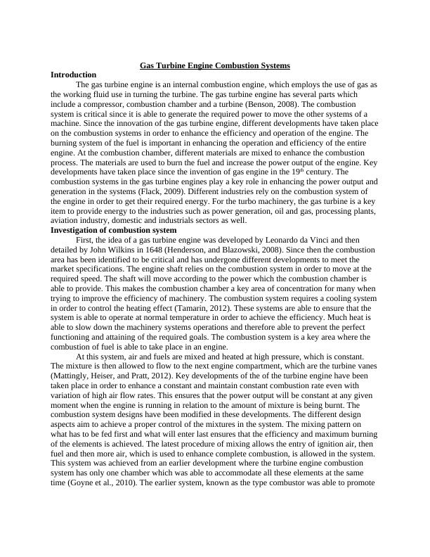
incomplete combustion since air and furl were being burnt at the same time. Of late, many types of combustion systems have been developed with different configurations. Annular, afterburners and cannular, also known as can-annular turbo-annular are some of the key combustion systems which are used in the gas turbine engines recently (Waltrup et al., 2012). The developments are meant to achieve some key aspects such as fuel efficiency, reduction of the emission levels to the environment and enhancing the transient response. The transient response is the response to the change of conditions such as the fuel flow and the speed at which air enters the combustion systems. The development to enhance these factors ensures that the power output from the combustion chamber can be control and prevent abnormal variations for the moving machines. Description of the developmentThe major objective in all the advancements and developments of the combustion system are aimed at adding the energy to the systems in order to power the turbines well. This is only achieved when the elements in the combustion system are well burnt and the efficiency is achieved at the combustion system (Mattingly, 2013). The combustion system efficiency ensuresthat the elements are burned and emitted at high velocity in form of a gas to the nozzles. The developments over the past have worked in order to balance the different engineering aspects in order to achieve the different design aspects which will maximise the power output.
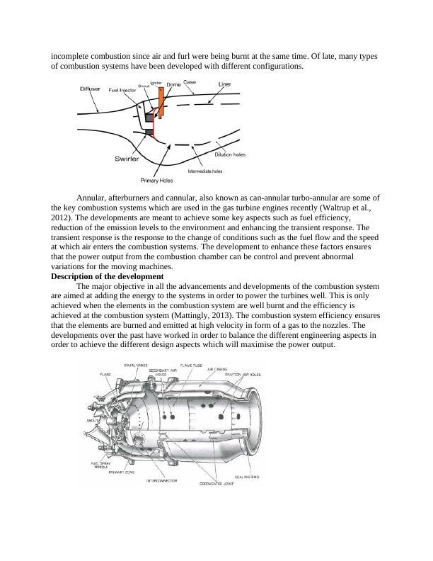
The combustion system has experienced developments in different areas. Some of the key areas which have experienced the developments include the emissions, operating ranges and the durability of the system. On these key areas, different components have been varied in order to meet some key aspects of the designs which were limiting. The advances on the gas turbine engines combustion systems are able to date as long as 1950s (Sturgess et al., 2009). In each development in these aspects, the design looks to address some key cons which are experienced in order to enhance the efficiency in power output or even other factors. Since the combustion system has different elements such as the casing, diffuser, fuel injector, dome, liner, dilution holes and primary holes, swirler among other parts, these components are changed in terms of design to achieve the required aspects during the developments. The developments have played acritical role in enhancing the operations of the combustion systems in these engines. One of the key developments on the gas engine combustion system in the 1950s was to enhance the control of the emissions from the engine. Reduction of the smoke emission by the gas engine has been one of the major goals (Matveev, and Serbin, 2012). The combustion process is able to lead to the production of the smoke, which is mostly an indicator of incompletecombustion of the fuel. The developments of enhancing the reduction of smoke emissions specifically were carried out in the 1950s. Smoke as seen, result from the incomplete combustionof the fuel. The main controller of combustion process is the injection of the air within the combustion chamber in order to enhance complete combustion of the fuel. Therefore, when it was noted that initial combustion system in the gas turbine engine did not support complete combustion; inlets were developed to allow injection of air at different stages. Through the injection of air at the initial stage and the final stage is able to control the combustion process and making sure that all the fuel is able to burn completely (Matveev, et al., 2013). The injection of air at different stages ensures even mixing of the fuel which was not achieved at the earlier engines. This ensures that the fuel will burn fully and control the smoke emission to the environment. In addition, the control of the smoke is also achieved through the kind of fuel injector used. The development of the modern fuel injector such as the airblast fuel injectors has been able to control the smoke emissions from the gas turbine engines. The fuel injectors developed are able to atomize the fuel and therefore able to eliminate the local pockets which result to high fuel concentration causing smoke. These allow proper burning of the fuel and ensuring that the smoke is controlled to the minimum levels. These types of injectors enhance theburning of the fuel completely and therefore smokeless. The fuel injector is a key part of the combustion systems in the gas turbine engine. Different types of injectors have been developed in order to enhance environmental friendliness of the engines (Jung and Becker, 2010). The control of smoke emissions has led to the development of the different fuel injectors for this engine. Some of the key injectors which have been used in this type of engine include the pressure atomizing injector, air blast injector, vaporizing and premix injectors. The initial fuel injector used for this engine was the pressure vaporizing injector. Although very simple to use, this injector was able to lead to incomplete combustion of the fuel and therefore increasing the smoke emission to the environment. The increased pollution from the use of this injector led to the development and use of other injectors which enhance complete burning of the fuel to control the pollutants (Eckardt and Rufli, 2010). The air blast injector was developed and was the first kind of smokeless injector to be used within the combustion system. This injector required less air pressure to atomize the fuel than theinitial fuel injector.
End of preview
Want to access all the pages? Upload your documents or become a member.
Related Documents
Operation and Performance of Turbine Enginelg...
|5
|805
|308
Gas Turbine Engine Combustion System Reportlg...
|18
|4656
|181
Internal Combustion Engines – A review of Theory and Performancelg...
|5
|2015
|62
Gas Turbine Engine: Combustion, Thermal Efficiency, and Systems Overviewlg...
|5
|938
|431
Forensic Engineering Failure Analysis and Preventionlg...
|14
|3504
|175
Increasing Efficiency of SI Engine with Turbocharging and Electrical Assistancelg...
|22
|4799
|350