HND Computing Unit 37: Global Hardware and Software Report Analysis
VerifiedAdded on 2023/01/05
|33
|10663
|81
Report
AI Summary
This report, likely prepared for a Higher National Diploma (HND) in Computing, delves into the intricacies of computer hardware and software. It begins by defining and differentiating between hardware and software components, emphasizing the functions of logical and physical components within a computer system. The report then explores various types of memory, including primary and secondary memory, detailing their roles and how they connect to the processor. Further, it discusses how data and programs are represented in a computer system, including floating-point number conversion and boolean logical operations. The report also investigates advanced computer architecture, focusing on the DirectX API, its pros and cons, and its control over graphics functions. It concludes by evaluating computer performance developments, particularly pipelining architectures and MIMD (Multiple Instruction, Multiple Data) systems. The report covers various aspects of computer architecture and performance.
Running head: GLOBAL HARDWARE AND SOFTWARE
GLOBAL HARDWARE AND SOFTWARE
Name of the Student
Name of the University
Author Note:
GLOBAL HARDWARE AND SOFTWARE
Name of the Student
Name of the University
Author Note:
Paraphrase This Document
Need a fresh take? Get an instant paraphrase of this document with our AI Paraphraser
1GLOBAL HARDWARE AND SOFTWARE
Table of Contents
L01: Examination of function of computer system Components........................................3
Introduction......................................................................................................................3
Logical/Physical component function.............................................................................3
Different types of memory, roles and attaching memory to the processor......................4
Description how processors are connected to the devices using buses and memory......6
Conclusion.....................................................................................................................10
References..........................................................................................................................11
L02: Discuss how data and programs are represented in the computer system................12
Introduction....................................................................................................................12
Discussion......................................................................................................................12
Representation of data and programs in the computer system......................................12
Conversion of floating point and storage in computer..................................................13
Boolean logical operation inclusive of adder circuit used for adding binary numbers. 14
ICE Target system debug operate in system..................................................................16
Conclusion.....................................................................................................................17
References..........................................................................................................................18
LO4: Investigate advance computer architecture and performance..................................19
Introduction:..................................................................................................................19
Discussion on DirectX API:..............................................................................................20
Demonstrating the pros and cons of the DirectX API:......................................................21
How DirectX API can control the graphics functions:......................................................22
Critically evaluations computer performance developments with Pipelining architectures
and MIMD:....................................................................................................................................23
Discussion on Pipelining architectures:.........................................................................23
Understanding computer performance improvements with MIMD:.............................26
Conclusion:........................................................................................................................27
References:........................................................................................................................28
2GLOBAL HARDWARE AND SOFTWARE
L01: Examination of function of computer system Components
Introduction
Computer can be stated as a combination of software and hardware, which is completely
integrated way. It mainly aims to provide different kind of functionalities for the user. Hardware
is nothing but the physical component for the system like memory devices, keyboard and
processor (Silberschatz, Gagne and Galvin 2018). Software mainly aims to set a list of programs
which is needed by hardware so that it can function properly. It merely comes up some basic
components that help in providing best working cycle for the system. Input process and Output
cycle are considered to be functional part of a system (Richter, Götzfried and Müller 2016). It
merely requires proper input and can easily produce the desired output.
Logical/Physical component function
Computer can be stated as a programmable machine that can easily read binary data
which passes instruction and process in binary data. It merely aims to pass instruction, process in
binary data and provides the required output (Khoroshilov, Kuliamin and Petrenko 2017).Their
digital computer is one which tend to work on the digital data.
Input Unit: This particular unit comprises input devices which are attached to the system.
In these devices, input is taken and completely changed into binary language, whichis
understood by system.
Central Processing Unit (CPU): As soon as the required information is entered in the
system by the given input device, then the processor will mainly process it. CPU is defined as the
brain the system as it is control system of the whole computer. It will merely first fetch the
required data from memory and then interprets it so that the next step can be understood (Kanev
et al . 2016). If needed, then the data is completely being fetched from both input devices and
memory. The main function of CPU is to execute or carry out the required computation along
with storing the overall output. The execution of CPU is done for required computation and then
store the overall output (Yildiz, Lekesiz and Yildiz 2016). The display is provided to the output
devices. CPU merely comes up with three major functions like arithmetic logic unit, control unit
and lastly memory unit.
Arithmetic logic unit: In ALU, all kind of mathematical calculation and logical decision
comes is done. Arithmetic calculation is merely inclusive of addition, subtraction, division and
multiplication (Dihoru et al. 2019). Logical decision is all about comparison of two given data
and analysing which one is larger.
Control unit: The main function of control unit is all about coordinating and controlling
the flow of data which is in and out of CPU. The mere focus is all about controlling the flow of
operation of ALU, memory registers and associated input/ Output units. The mere focus is all
about being carried all the required instruction, which is there in the program (Comer 2017). It
mainly decodes the given instruction along with interpreting it. All the required kind of signals
are sent to both input and output devices until and unless operation is done by both ALU and
memory.
Computers come up both electrical and mechanical equipment in a system is defined to
be as hardware. Some of the examples are motherboard, RAM, Processor, Monitor and Mouse.
Software is mainly used for describing various programs that carry out task on the given system.
Computer can be stated as a collection of both electronic and mechanical devices which operates
at a single unit. System unit are defined as the main container for various system devices. It is
⊘ This is a preview!⊘
Do you want full access?
Subscribe today to unlock all pages.

Trusted by 1+ million students worldwide
3GLOBAL HARDWARE AND SOFTWARE
required for protecting some of delicate mechanical and electronic devices from any kind of
damage. Some of the included devices are motherboard, disk driver, Ports and expansion cards.
Peripherals are devices which are connected to the given system by using cables or wireless
based technologies. Some of the typical peripherals like monitor, printer, scanner and speakers.
Processor come up with integrated circuit which is completely supplied on single silicon chip.
The main function is getting a complete control of all the computer function. Some of the major
manufacturers are AMD and Intel. System programs come up with set of instruction. In this the
program aim to run and the given processor aim to carry the whole instruction in proper way.
Some of the typical instructions are arithmetic, logical and Move. In the move function, the data
is completely moving from one place to another within the system. Required memory is needed
by processor for carrying out instruction.
The speed of processor is measured in either megahertz and gigahertz. The overall speed
of the clock is responsible for controlling the fact that how fast it can be executed. 1 MHz means
that 1 million clock will tick on every second basis. In the present multi-core processor, there are
around two, three and four processors available on single chip. Random access memory is known
to be computer memory where data programs are completely held in RAM. It is a volatile
memory which is lost when the system is turned off. The present used technology is DDR
(Double data ram) which are mainly of three types that are DDR1, DDR2 and DDR3.
Motherboard is also known as system board which comes up with a main circuit board for the
given system. All the given devices in system is considered to be a part of motherboard. There
are different kind of processor which need different socket so a particular motherboard needs to
be chosen for suiting the processor.
Chipset is needed for controlling the flow of data around the whole system. It comes up
with two kind of chips that is Northbridge and Southbridge. In Northbridge, the flow of data is
seen between memory and processor. It merely highlights the flow of data between processor
and required graphic card. In Southbridge, the flow of data is seen between devices that is USB,
SATA, LAN. It mainly aims to control PCI slot and on-board graphics. A bus can be stated as a
path by which data can be easily sent to various parts of the given computer system. System
power supply comes up with huge number of function like converting alternating current to
direct current.
Different types of memory, roles and attaching memory to the processor
Memory is considered to be an important part of system. Without any kind of need for
memory, a system becomes tough to use. Memory aims to play a key role in both retrieving and
saving of data (Yan, Song and Wu 2016). The overall performance of system mainly depends on
the size of the memory.
Paraphrase This Document
Need a fresh take? Get an instant paraphrase of this document with our AI Paraphraser
4GLOBAL HARDWARE AND SOFTWARE
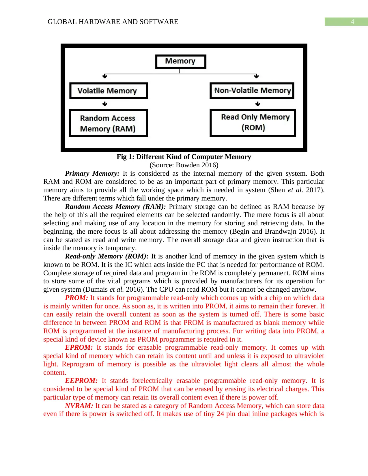
Fig 1: Different Kind of Computer Memory
(Source: Bowden 2016)
Primary Memory: It is considered as the internal memory of the given system. Both
RAM and ROM are considered to be as an important part of primary memory. This particular
memory aims to provide all the working space which is needed in system (Shen et al. 2017).
There are different terms which fall under the primary memory.
Random Access Memory (RAM): Primary storage can be defined as RAM because by
the help of this all the required elements can be selected randomly. The mere focus is all about
selecting and making use of any location in the memory for storing and retrieving data. In the
beginning, the mere focus is all about addressing the memory (Begin and Brandwajn 2016). It
can be stated as read and write memory. The overall storage data and given instruction that is
inside the memory is temporary.
Read-only Memory (ROM): It is another kind of memory in the given system which is
known to be ROM. It is the IC which acts inside the PC that is needed for performance of ROM.
Complete storage of required data and program in the ROM is completely permanent. ROM aims
to store some of the vital programs which is provided by manufacturers for its operation for
given system (Dumais et al. 2016). The CPU can read ROM but it cannot be changed anyhow.
PROM: It stands for programmable read-only which comes up with a chip on which data
is mainly written for once. As soon as, it is written into PROM, it aims to remain their forever. It
can easily retain the overall content as soon as the system is turned off. There is some basic
difference in between PROM and ROM is that PROM is manufactured as blank memory while
ROM is programmed at the instance of manufacturing process. For writing data into PROM, a
special kind of device known as PROM programmer is required in it.
EPROM: It stands for erasable programmable read-only memory. It comes up with
special kind of memory which can retain its content until and unless it is exposed to ultraviolet
light. Reprogram of memory is possible as the ultraviolet light clears all almost the whole
content.
EEPROM: It stands forelectrically erasable programmable read-only memory. It is
considered to be special kind of PROM that can be erased by erasing its electrical charges. This
particular type of memory can retain its overall content even if there is power off.
NVRAM: It can be stated as a category of Random Access Memory, which can store data
even if there is power is switched off. It makes use of tiny 24 pin dual inline packages which is
5GLOBAL HARDWARE AND SOFTWARE
needed for integrating chip. This merely helps in gaining power which is needed for the
functioning of CMOS.
Flash Memory: It can be defined as a non-volatile chip which is needed for storage and
data transfer between digital devices and system. It comes up with the ability to be
reprogrammed and easily erased. It can be stated as a kind of EEPROM. This kind of memory is
used in USB flash drives, digital camera and solid state devices.
Virtual Memory: This can be defined as a storage allocation based scheme in which
secondary memory can be easily addressed. It is considered to be a part of the whole main
memory. The present address of the program can easily make use of reference memory which is
completely distinguished from the memory address.
Secondary Memory: Secondary memory is known to be external and completely
permanent. Secondary memory is very much concerned with some magic memory. The given
secondary memory can be easily stored on large number of media devices like magnetic tapes
and floppy disk.
Magnetic Tapes: These particular tapes are mainly used for different system where large
data volume is being collected for much larger time. The overall cost of collecting data is
inexpensive. Tapes come up with magnetic material which has all the required data. Deck is
completely connected to central processor, and all the required information are completely read
from the given tape by the help of processor.
Magnetic Disk: Magnetic disk is mainly used in system that is made on the same given
principle. It tends to rotate at a much speed inside the system drive. Data is completely stored on
the given surface of the given disk (Silberschatz, Gagne and Galvin 2018). At present, magnetic
disk is considered to be much popular for getting direct access to the various storage device.
Each of the given disks mainly comprises of number of centric circles which are known as track.
Computer ports can be stated as interface which exist between system and peripheral
devices. It is mainly found on the backside of the computer but this also built on the front side of
the system for getting an easy access. Serial ports come up with 9-pin ports which is also called
com1 and Com2. Both mice and external computers are generally connected to these ports. On
the contrary, parallel port is 25-pin port which is connected to scanners, printers and external
hard drives. They are mainly defined as LPT ports that is LPT1 and LPT2.
There are mainly two kind of memory that is secondary memory and primary memory.
Primary memory mainly comprises of RAM, ROM, Cache memory, virtual memory and lastly
Hybrid memory. System mainly makes use of input and output channel so that they can easily
access the secondary channel. In this, transfer of required data takes place by making use of
immediate zone for primary storage. Secondary memory does lose the required data when the
given device for powered down that is it non-volatile in nature. Primary storage that is main
memory or internal memory is often easily accessible to CPU. The main feature of this
instruction is to read and execute it in proper way. Main memory can be connected either direct
and indirect way to the CPU bus through memory bus.
RAM comes up with two important kind of device like static RAM and dynamic RAM.
The major difference between the two is the lifetime of data which is being stored. SRAM can
easily retain whole of the content till the electrical power is being supplied. If anyhow the power
is turned off, then its content will be lost for forever. SRAM can retain the electrical power when
⊘ This is a preview!⊘
Do you want full access?
Subscribe today to unlock all pages.

Trusted by 1+ million students worldwide
6GLOBAL HARDWARE AND SOFTWARE
the power is being applied to the given chip. DRAM comes up with short data lifetime that is
timespan of four milliseconds. Memory of ROM is quite distinguishable by the kind of method
which is used for writing new data into them. The overall classification highlights the evolution
of ROM devices that is programmable to erasable one. EPROM stands for erasable and
programmable ROM which is programmed in exact way like PROM. EPROM can be easily
erased and programmed in repeatable. Hybrid memory devices come with the combine feature of
RAM and ROM that does not belong either of the group. This type of memory can be easily used
for reading and writing like RAM. Flash memory comes up with features which is needed by
memory devices. This kind of memory devices come up with properties like low cost, non-
volatile and high-density. Cache memory is mainly used by the central processing unit of the
system so that it can reduce the overall average time for accessing memory. This particular cache
is considered smaller and faster memory that aims to store copy of data.
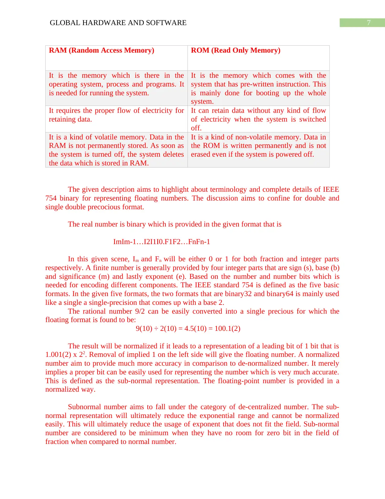
Compare the roles played by different types of memory
Paraphrase This Document
Need a fresh take? Get an instant paraphrase of this document with our AI Paraphraser
7GLOBAL HARDWARE AND SOFTWARE
RAM (Random Access Memory) ROM (Read Only Memory)
It is the memory which is there in the
operating system, process and programs. It
is needed for running the system.
It is the memory which comes with the
system that has pre-written instruction. This
is mainly done for booting up the whole
system.
It requires the proper flow of electricity for
retaining data.
It can retain data without any kind of flow
of electricity when the system is switched
off.
It is a kind of volatile memory. Data in the
RAM is not permanently stored. As soon as
the system is turned off, the system deletes
the data which is stored in RAM.
It is a kind of non-volatile memory. Data in
the ROM is written permanently and is not
erased even if the system is powered off.
The given description aims to highlight about terminology and complete details of IEEE
754 binary for representing floating numbers. The discussion aims to confine for double and
single double precocious format.
The real number is binary which is provided in the given format that is
ImIm-1…I2I1I0.F1F2…FnFn-1
In this given scene, Im and Fn will be either 0 or 1 for both fraction and integer parts
respectively. A finite number is generally provided by four integer parts that are sign (s), base (b)
and significance (m) and lastly exponent (e). Based on the number and number bits which is
needed for encoding different components. The IEEE standard 754 is defined as the five basic
formats. In the given five formats, the two formats that are binary32 and binary64 is mainly used
like a single a single-precision that comes up with a base 2.
The rational number 9/2 can be easily converted into a single precious for which the
floating format is found to be:
9(10) ÷ 2(10) = 4.5(10) = 100.1(2)
The result will be normalized if it leads to a representation of a leading bit of 1 bit that is
1.001(2) x 22. Removal of implied 1 on the left side will give the floating number. A normalized
number aim to provide much more accuracy in comparison to de-normalized number. It merely
implies a proper bit can be easily used for representing the number which is very much accurate.
This is defined as the sub-normal representation. The floating-point number is provided in a
normalized way.
Subnormal number aims to fall under the category of de-centralized number. The sub-
normal representation will ultimately reduce the exponential range and cannot be normalized
easily. This will ultimately reduce the usage of exponent that does not fit the field. Sub-normal
number are considered to be minimum when they have no room for zero bit in the field of
fraction when compared to normal number.
8GLOBAL HARDWARE AND SOFTWARE
The exponent field is expected to be 2 that is encoded like 129 (127+2) which is defined
as a biased component. The complete exponent field is based on a binary format which
highlights the negative exponents which are encoding. Biased component comes up with benefits
over the negative exponent which is needed for bitwise comparison for floating numbers.
In floating point, accuracy is completely represented by number of bits where the range is
limited by exponent. Real numbers can be represented by the floating point numbers. In the
given number which is not floating float point number, there are only two options which is
available for floating point approximation. The closet floating point is considered to be less than
x. The closest floating point number is much greater than the value x.
Overflow tends to occur when there is true result of an arithmetic operation is found to be
finite in nature but large in magnitude. Largest of the floating point number can be easily stored
by making use of precision. Underflow tends to occur when the true result of the arithmetic
operation is much smaller in magnitude. It is much smaller that the normalized floating point
number that can be easily stored.
IEEE 754 is defined like a binary floating point format. The architecture aims to provide
the left hardware manufacture. The complete storage order for the individual byte in the binary
floating point aim to vary from architecture to architecture.
P3: Representing of different types of data in a computer system
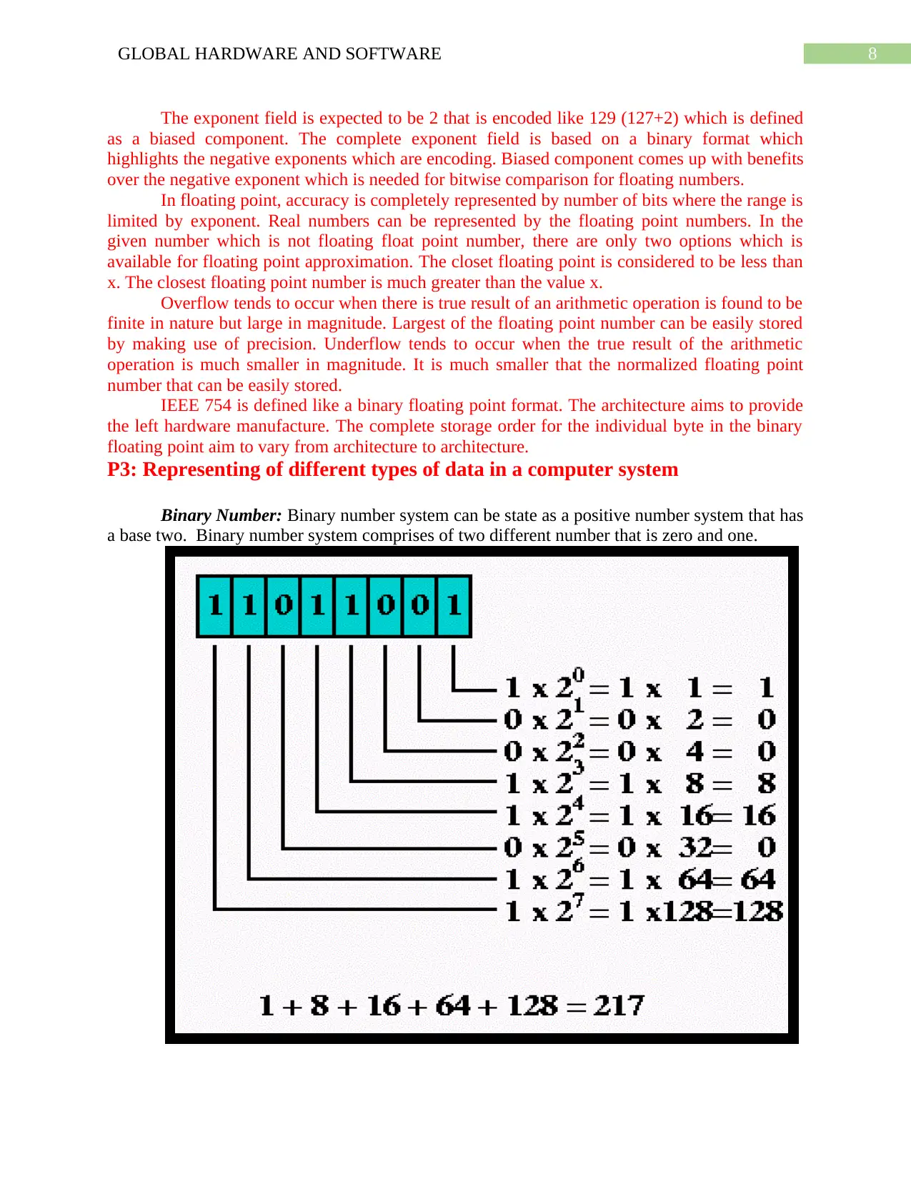
Binary Number: Binary number system can be state as a positive number system that has
a base two. Binary number system comprises of two different number that is zero and one.
⊘ This is a preview!⊘
Do you want full access?
Subscribe today to unlock all pages.

Trusted by 1+ million students worldwide
9GLOBAL HARDWARE AND SOFTWARE
Fig 1: Conversion of Binary Number to Decimal Number
(Source : Created by Author)
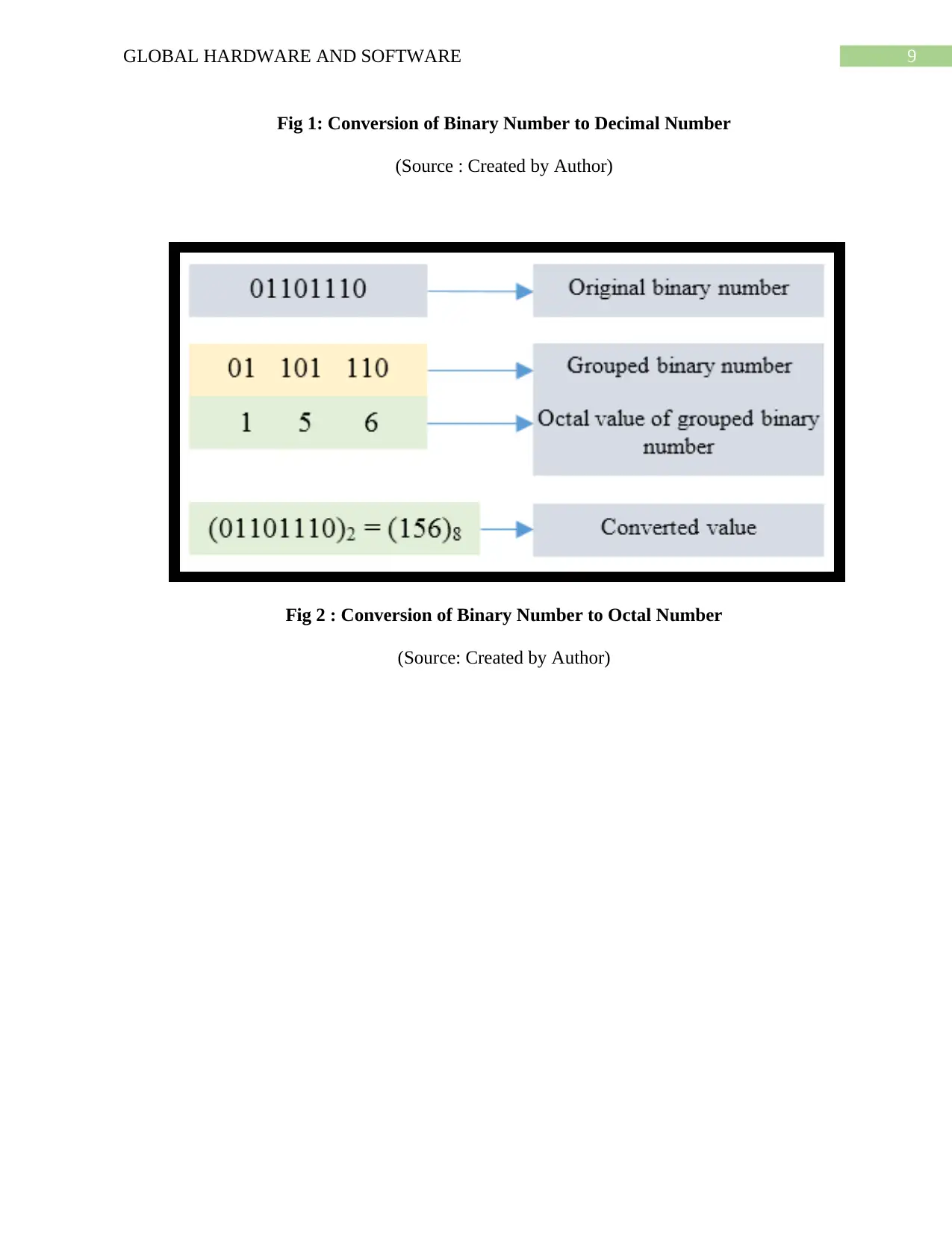
Fig 2 : Conversion of Binary Number to Octal Number
(Source: Created by Author)
Fig 1: Conversion of Binary Number to Decimal Number
(Source : Created by Author)
Fig 2 : Conversion of Binary Number to Octal Number
(Source: Created by Author)
Paraphrase This Document
Need a fresh take? Get an instant paraphrase of this document with our AI Paraphraser
10GLOBAL HARDWARE AND SOFTWARE
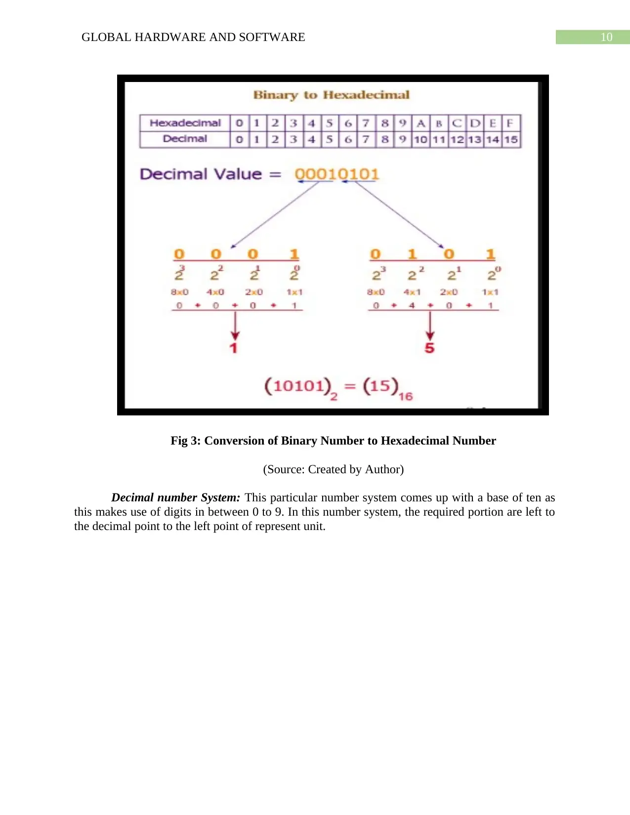
Fig 3: Conversion of Binary Number to Hexadecimal Number
(Source: Created by Author)
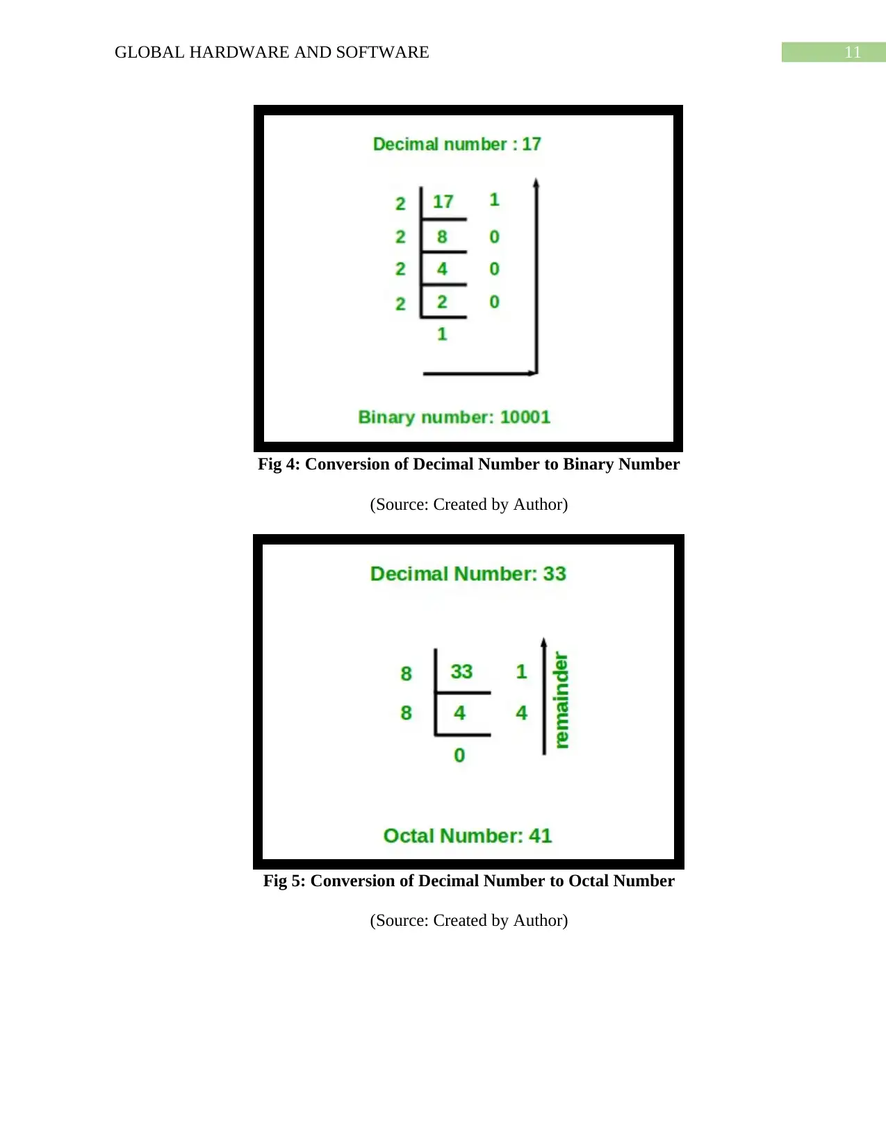
Decimal number System: This particular number system comes up with a base of ten as
this makes use of digits in between 0 to 9. In this number system, the required portion are left to
the decimal point to the left point of represent unit.
11GLOBAL HARDWARE AND SOFTWARE
Fig 4: Conversion of Decimal Number to Binary Number
(Source: Created by Author)
Fig 5: Conversion of Decimal Number to Octal Number
(Source: Created by Author)
Fig 4: Conversion of Decimal Number to Binary Number
(Source: Created by Author)
Fig 5: Conversion of Decimal Number to Octal Number
(Source: Created by Author)
⊘ This is a preview!⊘
Do you want full access?
Subscribe today to unlock all pages.

Trusted by 1+ million students worldwide
1 out of 33
Related Documents
Your All-in-One AI-Powered Toolkit for Academic Success.
+13062052269
info@desklib.com
Available 24*7 on WhatsApp / Email
![[object Object]](/_next/static/media/star-bottom.7253800d.svg)
Unlock your academic potential
Copyright © 2020–2026 A2Z Services. All Rights Reserved. Developed and managed by ZUCOL.


