Constant conductivity and No Heat Generation Assignment 2022
VerifiedAdded on 2022/09/18
|18
|1411
|34
Assignment
AI Summary
Contribute Materials
Your contribution can guide someone’s learning journey. Share your
documents today.

ASSIGNMENT
By
(Name)
(Course)
(Professor’s Name)
(Institution)
(State)
(Date)
By
(Name)
(Course)
(Professor’s Name)
(Institution)
(State)
(Date)
Secure Best Marks with AI Grader
Need help grading? Try our AI Grader for instant feedback on your assignments.
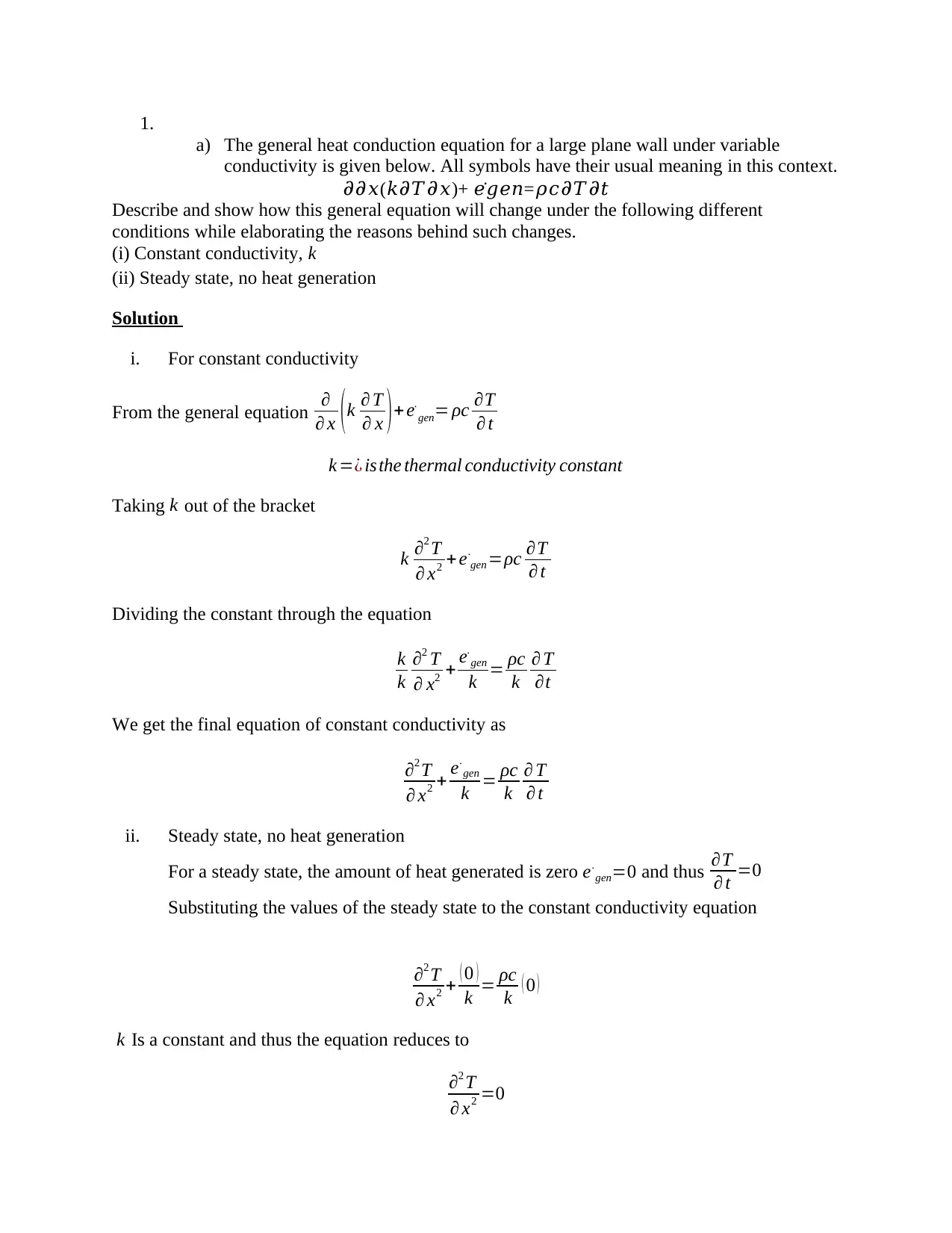
1.
a) The general heat conduction equation for a large plane wall under variable
conductivity is given below. All symbols have their usual meaning in this context.
𝜕𝜕𝑥(𝑘𝜕𝑇𝜕𝑥)+ 𝑒̇ 𝑔𝑒𝑛=𝜌𝑐𝜕𝑇𝜕𝑡
Describe and show how this general equation will change under the following different
conditions while elaborating the reasons behind such changes.
(i) Constant conductivity, k
(ii) Steady state, no heat generation
Solution
i. For constant conductivity
From the general equation ∂
∂ x (k ∂ T
∂ x )+ e.
gen= ρc ∂T
∂ t
k =¿ isthe thermal conductivity constant
Taking k out of the bracket
k ∂2 T
∂ x2 + e.
gen =ρc ∂T
∂ t
Dividing the constant through the equation
k
k
∂2 T
∂ x2 + e.
gen
k = ρc
k
∂ T
∂t
We get the final equation of constant conductivity as
∂2 T
∂ x2 + e.
gen
k = ρc
k
∂ T
∂ t
ii. Steady state, no heat generation
For a steady state, the amount of heat generated is zero e.
gen=0 and thus ∂T
∂ t =0
Substituting the values of the steady state to the constant conductivity equation
∂2 T
∂ x2 + ( 0 )
k = ρc
k ( 0 )
k Is a constant and thus the equation reduces to
∂2 T
∂ x2 =0
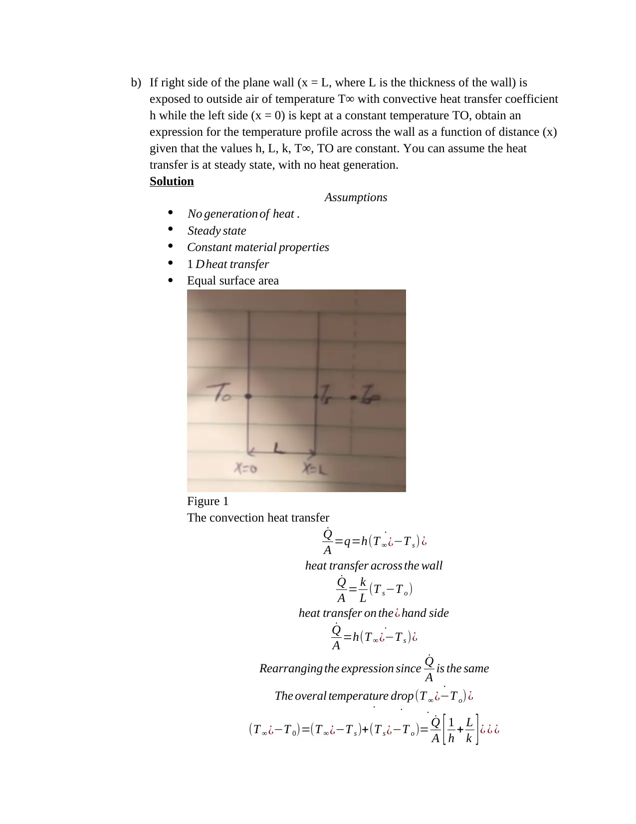
b) If right side of the plane wall (x = L, where L is the thickness of the wall) is
exposed to outside air of temperature T∞ with convective heat transfer coefficient
h while the left side (x = 0) is kept at a constant temperature TO, obtain an
expression for the temperature profile across the wall as a function of distance (x)
given that the values h, L, k, T∞, TO are constant. You can assume the heat
transfer is at steady state, with no heat generation.
Solution
Assumptions
No generation of heat .
Steady state
Constant material properties
1 Dheat transfer
Equal surface area
Figure 1
The convection heat transfer
˙Q
A = ˙q=h(T ∞ ¿−T s ) ¿
heat transfer across the wall
˙Q
A = k
L (T s−T o )
heat transfer on the¿ hand side
˙Q
A = ˙h(T ∞ ¿−T s )¿
Rearranging the expression since ˙Q
A is the same
The overal temperature drop ˙(T ∞ ¿−T o) ¿
˙
(T ∞ ¿−T 0)=
˙
(T ∞ ¿−T s )+ ˙
(T s ¿−T o )= ˙Q
A [ 1
h + L
k ] ¿ ¿ ¿
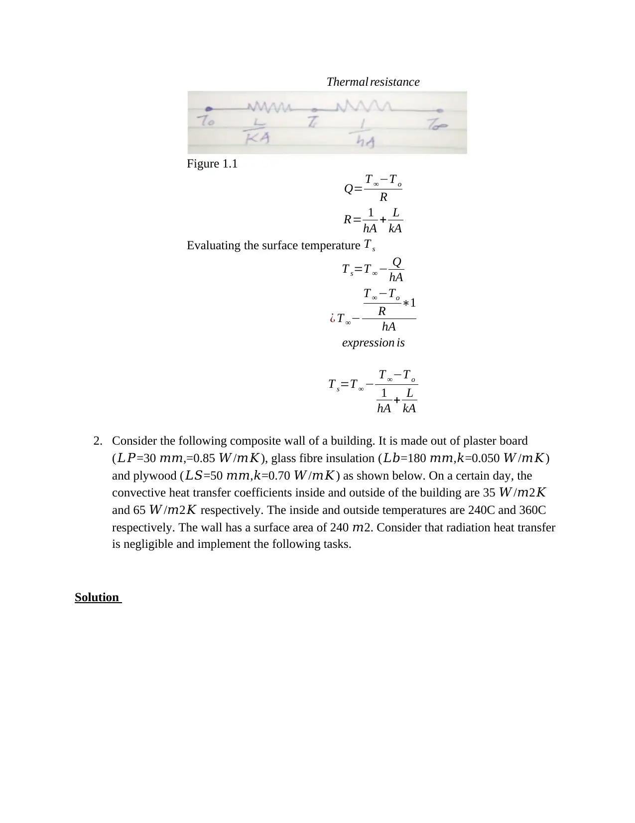
Thermal resistance
Figure 1.1
Q= T ∞−T o
R
R= 1
hA + L
kA
Evaluating the surface temperature T s
T s=T ∞ − Q
hA
¿ T ∞−
T ∞ −To
R ∗1
hA
expression is
T s=T ∞ − T ∞−T o
1
hA + L
kA
2. Consider the following composite wall of a building. It is made out of plaster board
(𝐿𝑃=30 𝑚𝑚,=0.85 𝑊/𝑚𝐾), glass fibre insulation (𝐿𝑏=180 𝑚𝑚,𝑘=0.050 𝑊/𝑚𝐾)
and plywood (𝐿𝑆=50 𝑚𝑚,𝑘=0.70 𝑊/𝑚𝐾) as shown below. On a certain day, the
convective heat transfer coefficients inside and outside of the building are 35 𝑊/𝑚2𝐾
and 65 𝑊/𝑚2𝐾 respectively. The inside and outside temperatures are 240C and 360C
respectively. The wall has a surface area of 240 𝑚2. Consider that radiation heat transfer
is negligible and implement the following tasks.
Solution
Secure Best Marks with AI Grader
Need help grading? Try our AI Grader for instant feedback on your assignments.
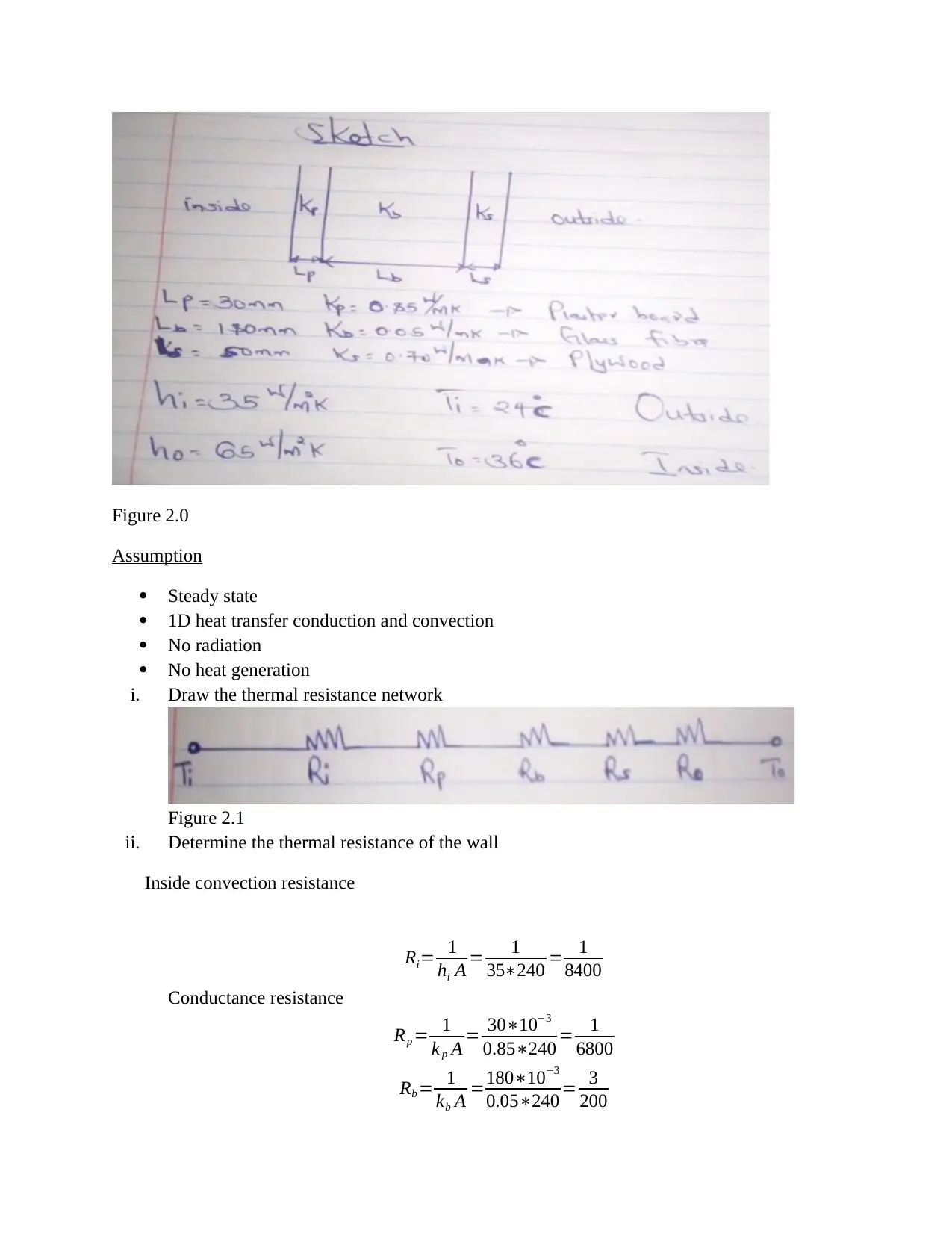
Figure 2.0
Assumption
Steady state
1D heat transfer conduction and convection
No radiation
No heat generation
i. Draw the thermal resistance network
Figure 2.1
ii. Determine the thermal resistance of the wall
Inside convection resistance
Ri= 1
hi A = 1
35∗240 = 1
8400
Conductance resistance
Rp = 1
k p A = 30∗10−3
0.85∗240 = 1
6800
Rb = 1
kb A =180∗10−3
0.05∗240 = 3
200
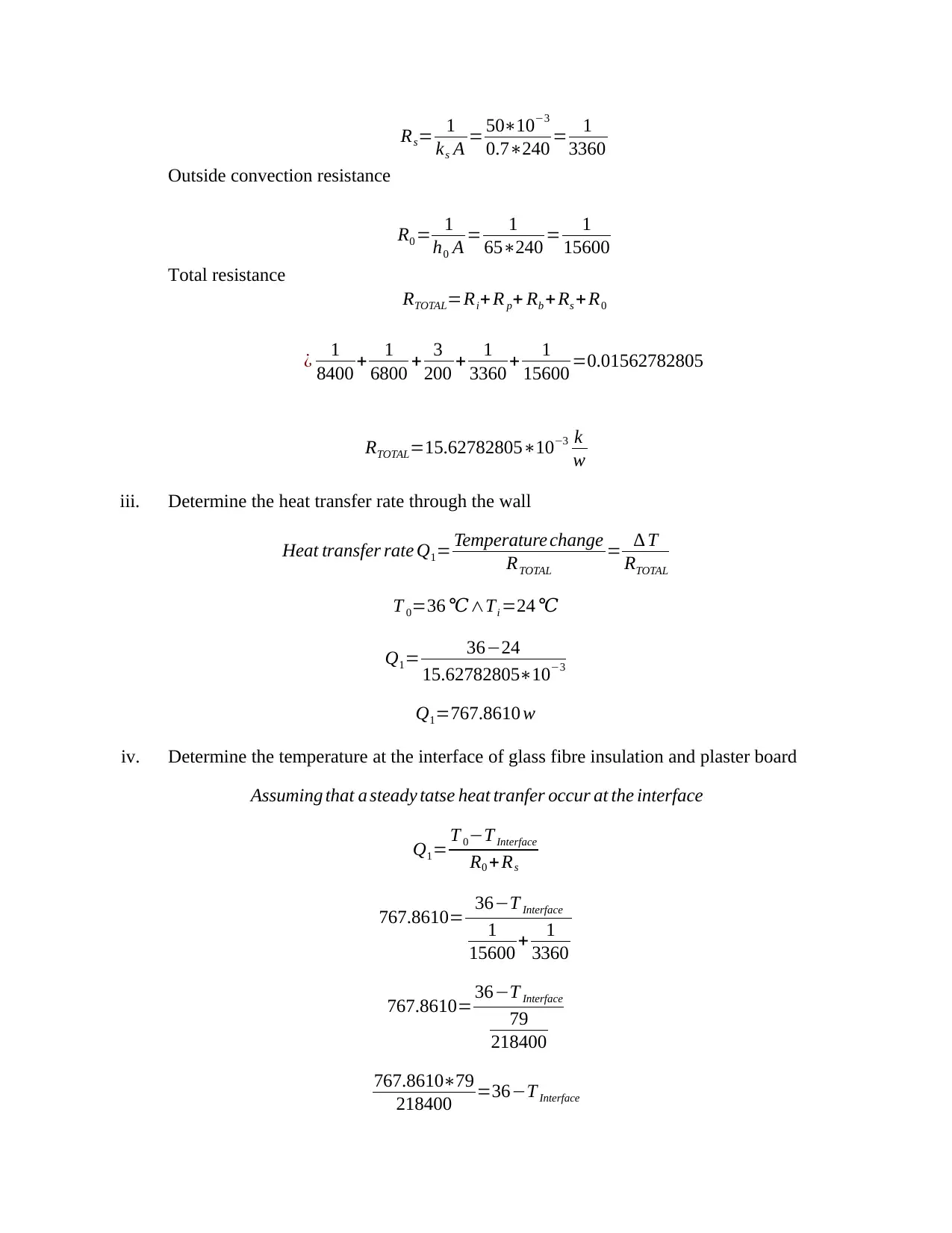
Rs= 1
ks A = 50∗10−3
0.7∗240 = 1
3360
Outside convection resistance
R0 = 1
h0 A = 1
65∗240 = 1
15600
Total resistance
RTOTAL=Ri+ R p+ Rb + Rs + R0
¿ 1
8400 + 1
6800 + 3
200 + 1
3360 + 1
15600 =0.01562782805
RTOTAL=15.62782805∗10−3 k
w
iii. Determine the heat transfer rate through the wall
Heat transfer rate Q1= Temperature change
RTOTAL
= ∆ T
RTOTAL
T 0=36 ℃∧Ti =24 ℃
Q1= 36−24
15.62782805∗10−3
Q1=767.8610 w
iv. Determine the temperature at the interface of glass fibre insulation and plaster board
Assuming that a steady tatse heat tranfer occur at the interface
Q1= T 0−T Interface
R0 + Rs
767.8610= 36−T Interface
1
15600 + 1
3360
767.8610= 36−T Interface
79
218400
767.8610∗79
218400 =36−T Interface
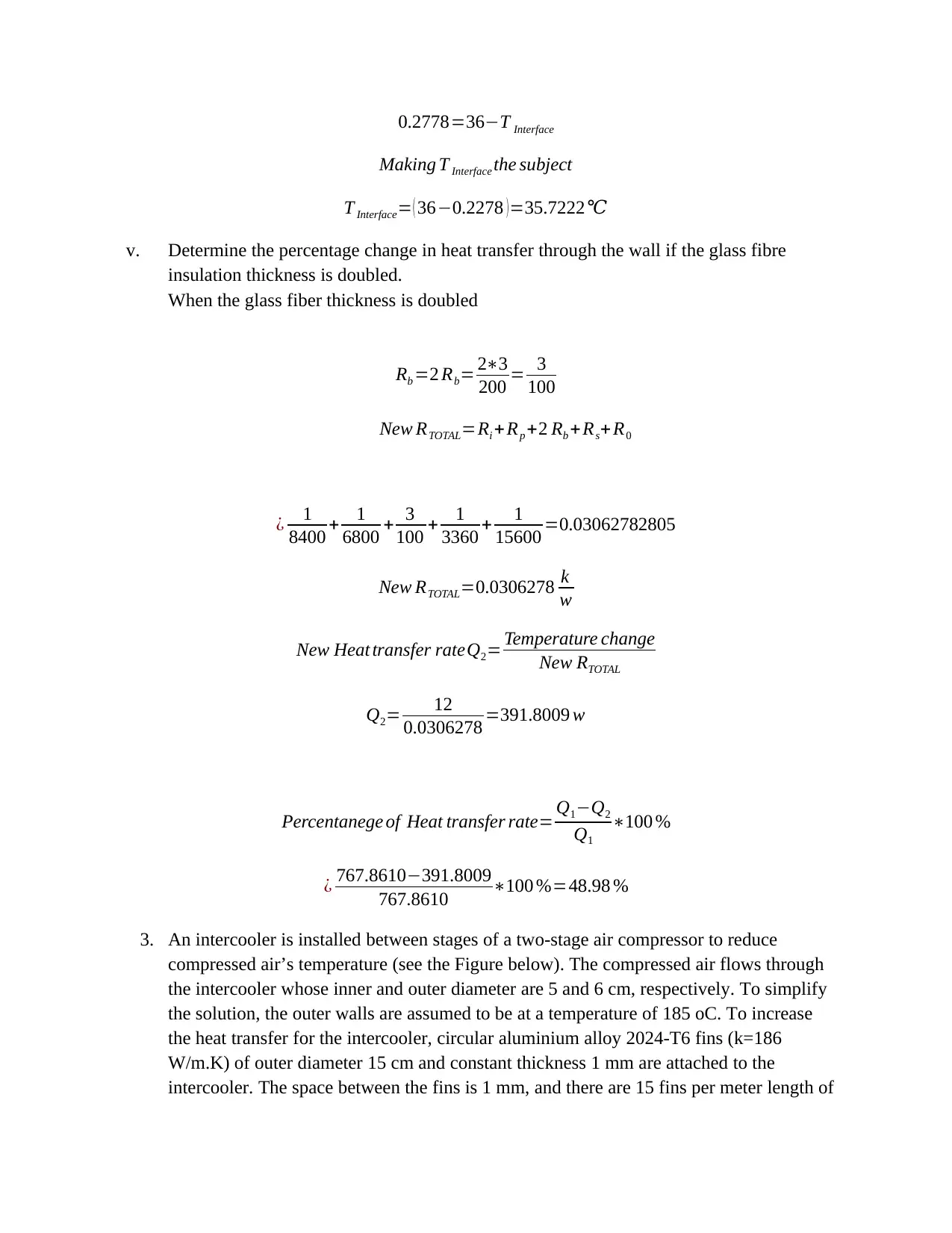
0.2778=36−T Interface
Making T Interface the subject
T Interface= ( 36−0.2278 ) =35.7222℃
v. Determine the percentage change in heat transfer through the wall if the glass fibre
insulation thickness is doubled.
When the glass fiber thickness is doubled
Rb =2 Rb= 2∗3
200 = 3
100
New RTOTAL=Ri +Rp +2 Rb +Rs+R0
¿ 1
8400 + 1
6800 + 3
100 + 1
3360 + 1
15600 =0.03062782805
New RTOTAL=0.0306278 k
w
New Heat transfer rateQ2= Temperature change
New RTOTAL
Q2= 12
0.0306278 =391.8009 w
Percentanege of Heat transfer rate= Q1−Q2
Q1
∗100 %
¿ 767.8610−391.8009
767.8610 ∗100 %=48.98 %
3. An intercooler is installed between stages of a two-stage air compressor to reduce
compressed air’s temperature (see the Figure below). The compressed air flows through
the intercooler whose inner and outer diameter are 5 and 6 cm, respectively. To simplify
the solution, the outer walls are assumed to be at a temperature of 185 oC. To increase
the heat transfer for the intercooler, circular aluminium alloy 2024-T6 fins (k=186
W/m.K) of outer diameter 15 cm and constant thickness 1 mm are attached to the
intercooler. The space between the fins is 1 mm, and there are 15 fins per meter length of
Paraphrase This Document
Need a fresh take? Get an instant paraphrase of this document with our AI Paraphraser
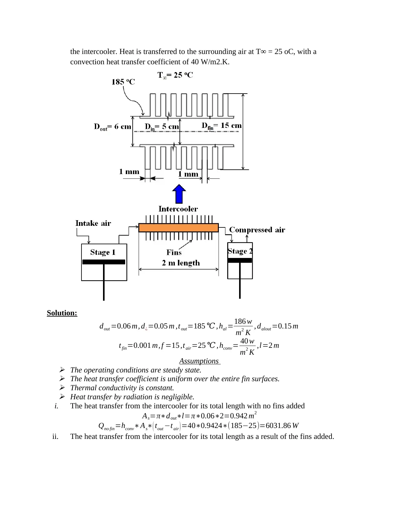
the intercooler. Heat is transferred to the surrounding air at T∞ = 25 oC, with a
convection heat transfer coefficient of 40 W/m2.K.
Solution:
dout =0.06 m, d¿=0.05 m ,tout=185 ℃ , hal =186 w
m2 K , dalout =0.15 m
tfin=0.001 m, f =15 ,tair=25 ℃ , hconv= 40 w
m2 K ,l=2 m
Assumptions
The operating conditions are steady state.
The heat transfer coefficient is uniform over the entire fin surfaces.
Thermal conductivity is constant.
Heat transfer by radiation is negligible.
i. The heat transfer from the intercooler for its total length with no fins added
As=π∗dout∗l=π∗0.06∗2=0.942 m2
Qno fin=hconv∗As∗( tout −tair ) =40∗0.9424∗(185−25)=6031.86 W
ii. The heat transfer from the intercooler for its total length as a result of the fins added.
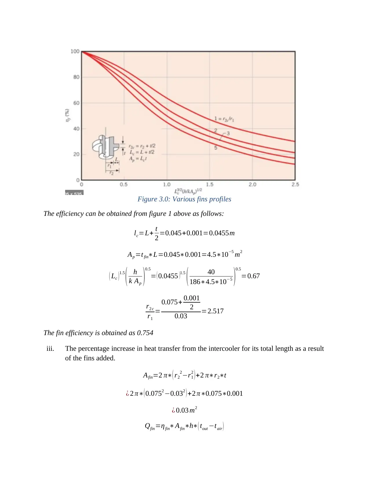
Figure 3.0: Various fins profiles
The efficiency can be obtained from figure 1 above as follows:
lc=L+ t
2 =0.045+0.001=0.0455m
Ap =tfin∗L=0.045∗0.001=4.5∗10−5 m2
( Lc ) 1.5
( h
k Ap )
0.5
= ( 0.0455 )1.5
( 40
186∗4.5∗10−5 )
0.5
=0.67
r2 c
r1
=
0.075+ 0.001
2
0.03 =2.517
The fin efficiency is obtained as 0.754
iii. The percentage increase in heat transfer from the intercooler for its total length as a result
of the fins added.
Afin=2 π∗( r2
2−r1
2 )+2 π∗r2∗t
¿ 2 π∗( 0.0752 −0.032 ) +2 π∗0.075∗0.001
¿ 0.03 m2
Qfin=ηfin∗Afin∗h∗( tout −tair )
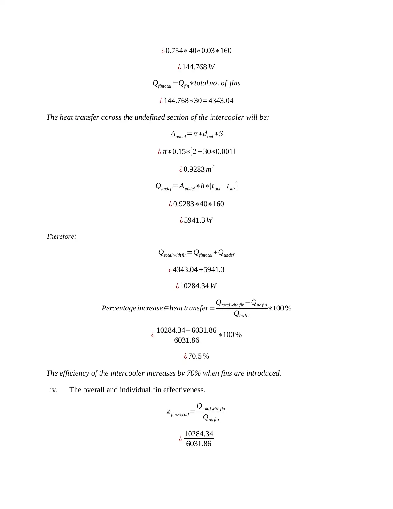
¿ 0.754∗40∗0.03∗160
¿ 144.768 W
Qfintotal =Qfin∗total no . of fins
¿ 144.768∗30=4343.04
The heat transfer across the undefined section of the intercooler will be:
Aundef =π∗dout∗S
¿ π∗0.15∗( 2−30∗0.001 )
¿ 0.9283 m2
Qundef = Aundef∗h∗( tout−tair )
¿ 0.9283∗40∗160
¿ 5941.3 W
Therefore:
Qtotal with fin=Qfintotal +Qundef
¿ 4343.04 +5941.3
¿ 10284.34 W
Percentage increase ∈heat transfer=Qtotal with fin −Qno fin
Qno fin
∗100 %
¿ 10284.34−6031.86
6031.86 ∗100 %
¿ 70.5 %
The efficiency of the intercooler increases by 70% when fins are introduced.
iv. The overall and individual fin effectiveness.
ϵfinoverall= Qtotal with fin
Qno fin
¿ 10284.34
6031.86
Secure Best Marks with AI Grader
Need help grading? Try our AI Grader for instant feedback on your assignments.
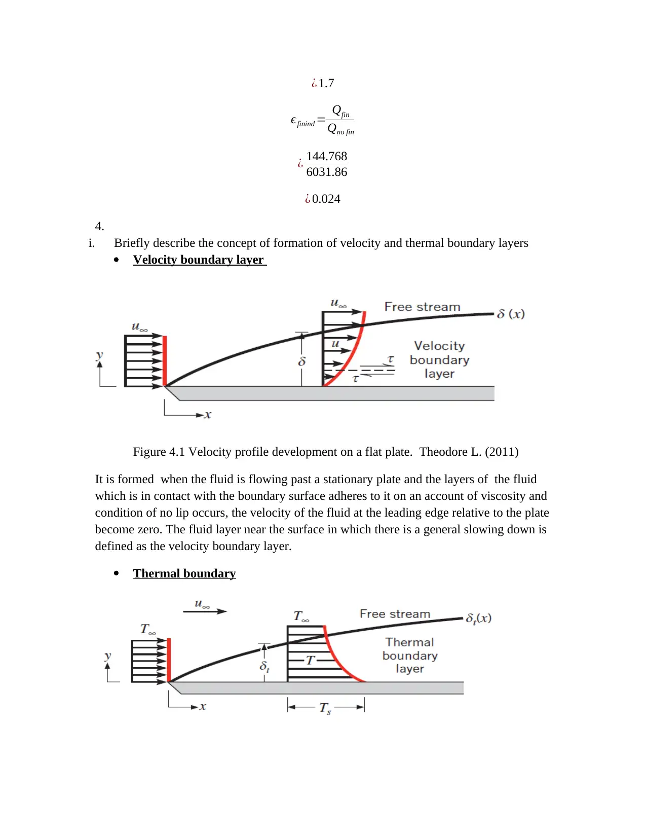
¿ 1.7
ϵfinind = Qfin
Qno fin
¿ 144.768
6031.86
¿ 0.024
4.
i. Briefly describe the concept of formation of velocity and thermal boundary layers
Velocity boundary layer
Figure 4.1 Velocity profile development on a flat plate. Theodore L. (2011)
It is formed when the fluid is flowing past a stationary plate and the layers of the fluid
which is in contact with the boundary surface adheres to it on an account of viscosity and
condition of no lip occurs, the velocity of the fluid at the leading edge relative to the plate
become zero. The fluid layer near the surface in which there is a general slowing down is
defined as the velocity boundary layer.
Thermal boundary
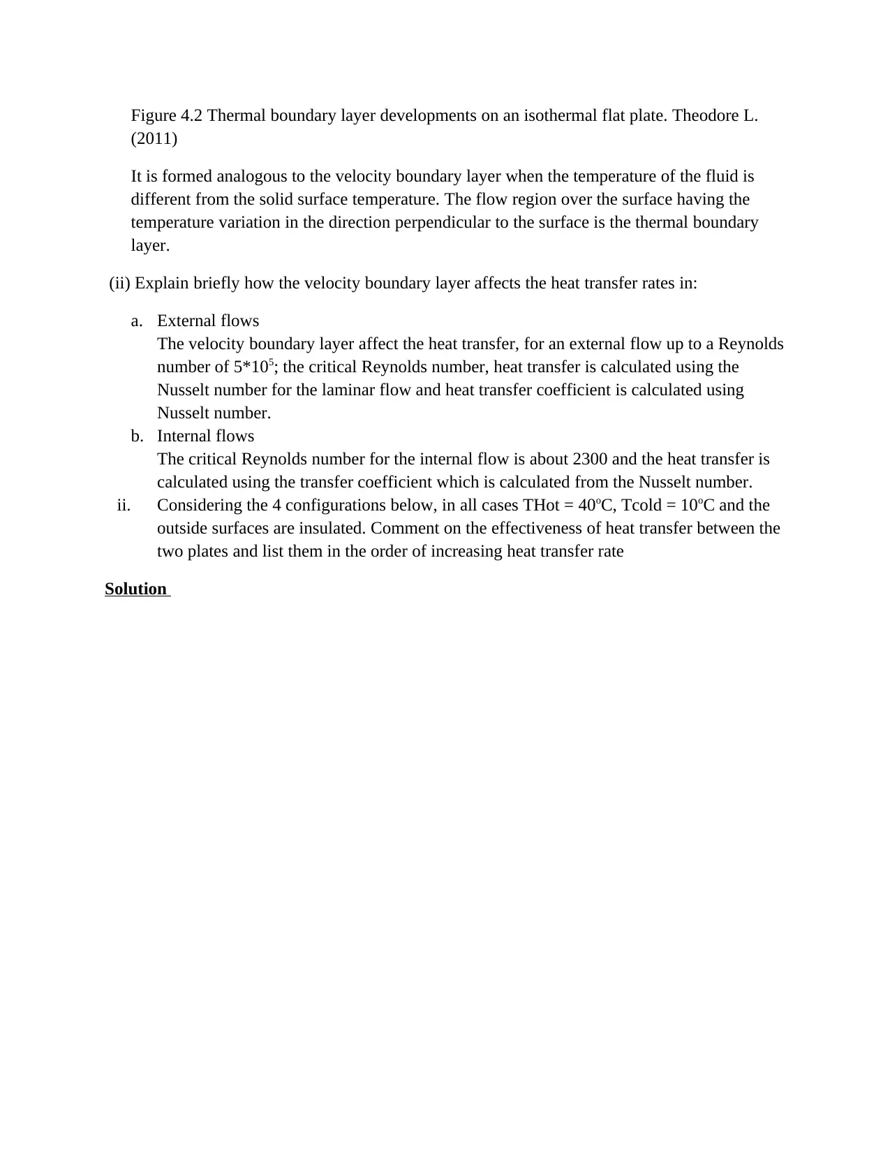
Figure 4.2 Thermal boundary layer developments on an isothermal flat plate. Theodore L.
(2011)
It is formed analogous to the velocity boundary layer when the temperature of the fluid is
different from the solid surface temperature. The flow region over the surface having the
temperature variation in the direction perpendicular to the surface is the thermal boundary
layer.
(ii) Explain briefly how the velocity boundary layer affects the heat transfer rates in:
a. External flows
The velocity boundary layer affect the heat transfer, for an external flow up to a Reynolds
number of 5*105; the critical Reynolds number, heat transfer is calculated using the
Nusselt number for the laminar flow and heat transfer coefficient is calculated using
Nusselt number.
b. Internal flows
The critical Reynolds number for the internal flow is about 2300 and the heat transfer is
calculated using the transfer coefficient which is calculated from the Nusselt number.
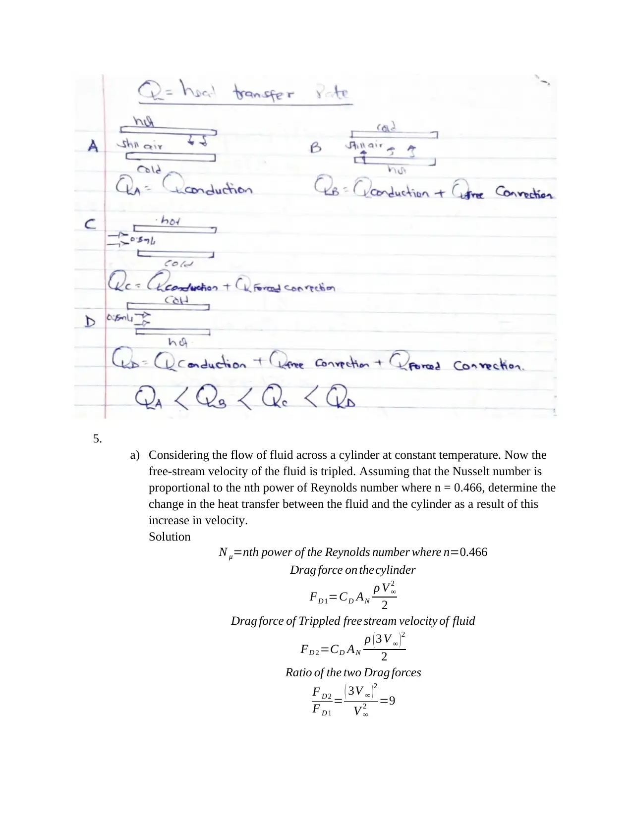
ii. Considering the 4 configurations below, in all cases THot = 40oC, Tcold = 10oC and the
outside surfaces are insulated. Comment on the effectiveness of heat transfer between the
two plates and list them in the order of increasing heat transfer rate
Solution
5.
a) Considering the flow of fluid across a cylinder at constant temperature. Now the
free-stream velocity of the fluid is tripled. Assuming that the Nusselt number is
proportional to the nth power of Reynolds number where n = 0.466, determine the
change in the heat transfer between the fluid and the cylinder as a result of this
increase in velocity.
Solution
N μ=nth power of the Reynolds number where n=0.466
Drag force on thecylinder
FD 1=CD AN
ρ V ∞
2
2
Drag force of Trippled free stream velocity of fluid
FD 2 =CD AN
ρ ( 3 V ∞ )2
2
Ratio of the two Drag forces
F D 2
F D 1
= ( 3V ∞ )2
V ∞
2 =9
Paraphrase This Document
Need a fresh take? Get an instant paraphrase of this document with our AI Paraphraser
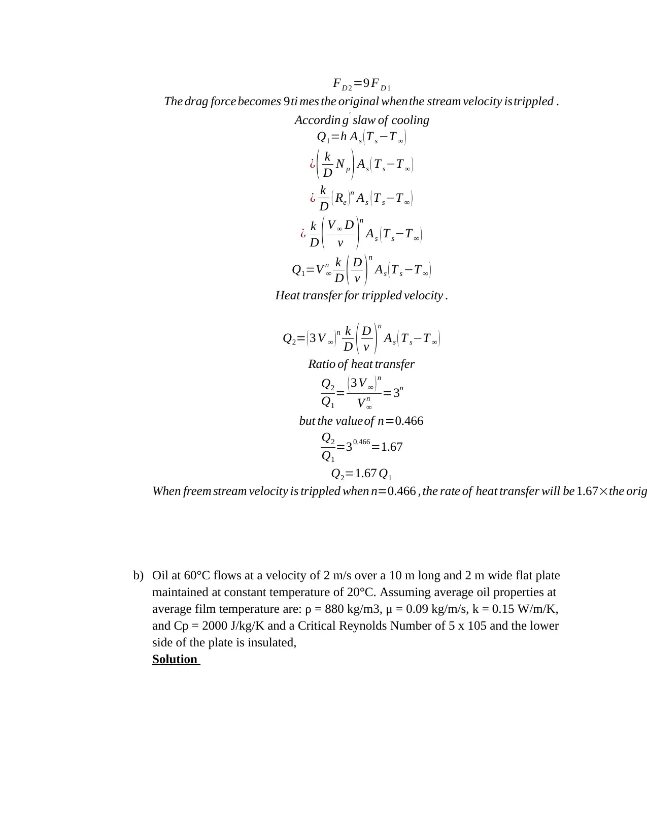
FD 2 =9 F D 1
The drag force becomes 9ti mes the original whenthe stream velocity istrippled .
Accordin g' slaw of cooling
Q1=h As ( T s −T ∞ )
¿ ( k
D N μ ) As ( T s−T ∞ )
¿ k
D ( Re )n As ( T s−T ∞ )
¿ k
D ( V ∞ D
v )n
As ( T s−T ∞ )
Q1=V ∞
n k
D ( D
v )n
As ( T s −T ∞ )
Heat transfer for trippled velocity .
Q2= ( 3 V ∞ ) n k
D ( D
v )
n
As ( T s−T ∞ )
Ratio of heat transfer
Q2
Q1
= ( 3 V ∞ )n
V ∞
n =3n
but the valueof n=0.466
Q2
Q1
=30.466=1.67
Q2=1.67 Q1
When freem stream velocity is trippled when n=0.466 , the rate of heat transfer will be 1.67×the orig
b) Oil at 60°C flows at a velocity of 2 m/s over a 10 m long and 2 m wide flat plate
maintained at constant temperature of 20°C. Assuming average oil properties at
average film temperature are: ρ = 880 kg/m3, μ = 0.09 kg/m/s, k = 0.15 W/m/K,
and Cp = 2000 J/kg/K and a Critical Reynolds Number of 5 x 10⁵ and the lower
side of the plate is insulated,
Solution
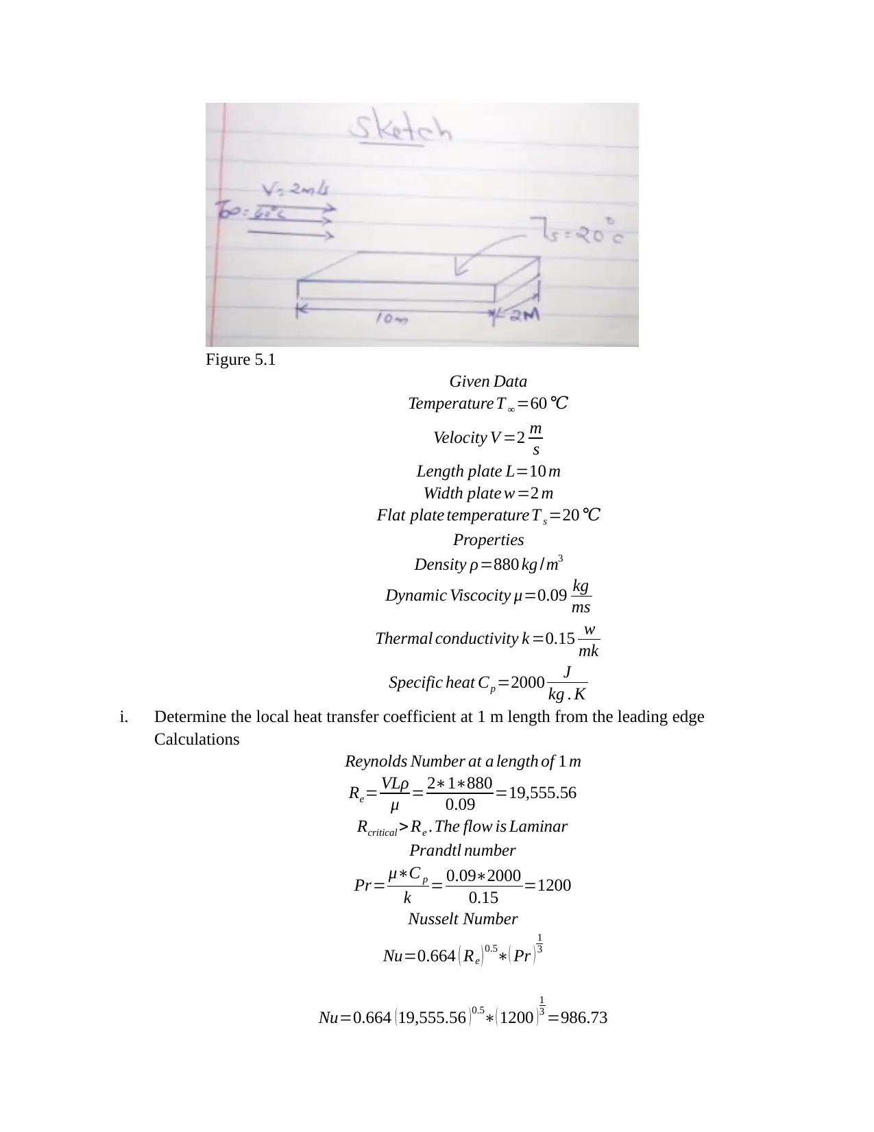
Figure 5.1
Given Data
Temperature T ∞ =60 ℃
Velocity V =2 m
s
Length plate L=10 m
Width plate w=2 m
Flat plate temperature T s =20 ℃
Properties
Density ρ=880 kg /m3
Dynamic Viscocity μ=0.09 kg
ms
Thermal conductivity k =0.15 w
mk
Specific heat Cp =2000 J
kg . K
i. Determine the local heat transfer coefficient at 1 m length from the leading edge
Calculations
Reynolds Number at a length of 1 m
Re= VLρ
μ = 2∗1∗880
0.09 =19,555.56
Rcritical > Re .The flow is Laminar
Prandtl number
Pr= μ∗C p
k = 0.09∗2000
0.15 =1200
Nusselt Number
Nu=0.664 ( Re ) 0.5∗( Pr )
1
3
Nu=0.664 (19,555.56 )0.5∗( 1200 )
1
3 =986.73
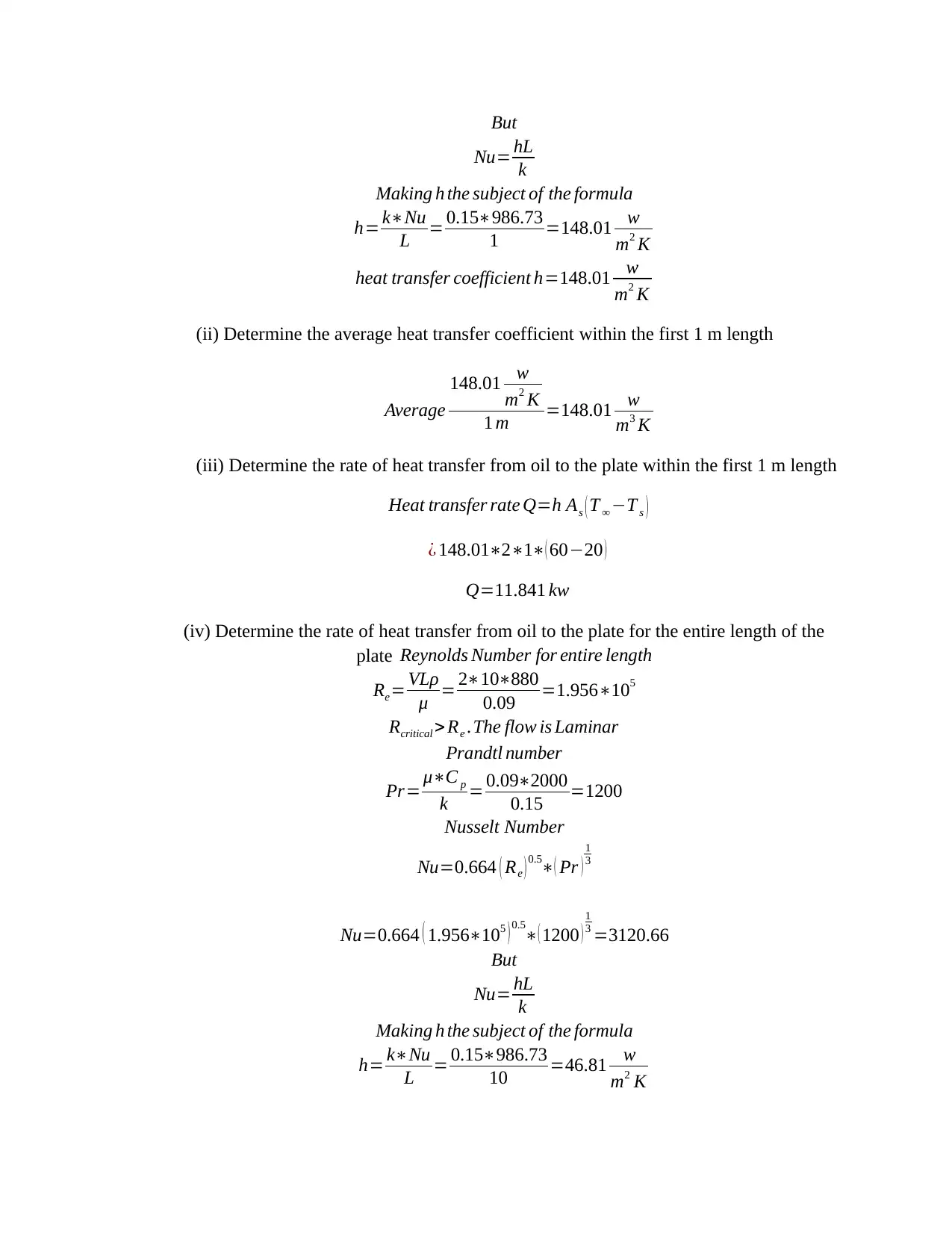
But
Nu= hL
k
Making h the subject of the formula
h= k∗Nu
L = 0.15∗986.73
1 =148.01 w
m2 K
heat transfer coefficient h=148.01 w
m2 K
(ii) Determine the average heat transfer coefficient within the first 1 m length
Average
148.01 w
m2 K
1 m =148.01 w
m3 K
(iii) Determine the rate of heat transfer from oil to the plate within the first 1 m length
Heat transfer rate Q=h As ( T ∞ −T s )
¿ 148.01∗2∗1∗( 60−20 )
Q=11.841 kw
(iv) Determine the rate of heat transfer from oil to the plate for the entire length of the
plate Reynolds Number for entire length
Re= VLρ
μ = 2∗10∗880
0.09 =1.956∗105
Rcritical > Re .The flow is Laminar
Prandtl number
Pr= μ∗C p
k = 0.09∗2000
0.15 =1200
Nusselt Number
Nu=0.664 ( Re ) 0.5∗( Pr )
1
3
Nu=0.664 ( 1.956∗105 ) 0.5
∗( 1200 )
1
3 =3120.66
But
Nu= hL
k
Making h the subject of the formula
h= k∗Nu
L = 0.15∗986.73
10 =46.81 w
m2 K
Nu= hL
k
Making h the subject of the formula
h= k∗Nu
L = 0.15∗986.73
1 =148.01 w
m2 K
heat transfer coefficient h=148.01 w
m2 K
(ii) Determine the average heat transfer coefficient within the first 1 m length
Average
148.01 w
m2 K
1 m =148.01 w
m3 K
(iii) Determine the rate of heat transfer from oil to the plate within the first 1 m length
Heat transfer rate Q=h As ( T ∞ −T s )
¿ 148.01∗2∗1∗( 60−20 )
Q=11.841 kw
(iv) Determine the rate of heat transfer from oil to the plate for the entire length of the
plate Reynolds Number for entire length
Re= VLρ
μ = 2∗10∗880
0.09 =1.956∗105
Rcritical > Re .The flow is Laminar
Prandtl number
Pr= μ∗C p
k = 0.09∗2000
0.15 =1200
Nusselt Number
Nu=0.664 ( Re ) 0.5∗( Pr )
1
3
Nu=0.664 ( 1.956∗105 ) 0.5
∗( 1200 )
1
3 =3120.66
But
Nu= hL
k
Making h the subject of the formula
h= k∗Nu
L = 0.15∗986.73
10 =46.81 w
m2 K
Secure Best Marks with AI Grader
Need help grading? Try our AI Grader for instant feedback on your assignments.
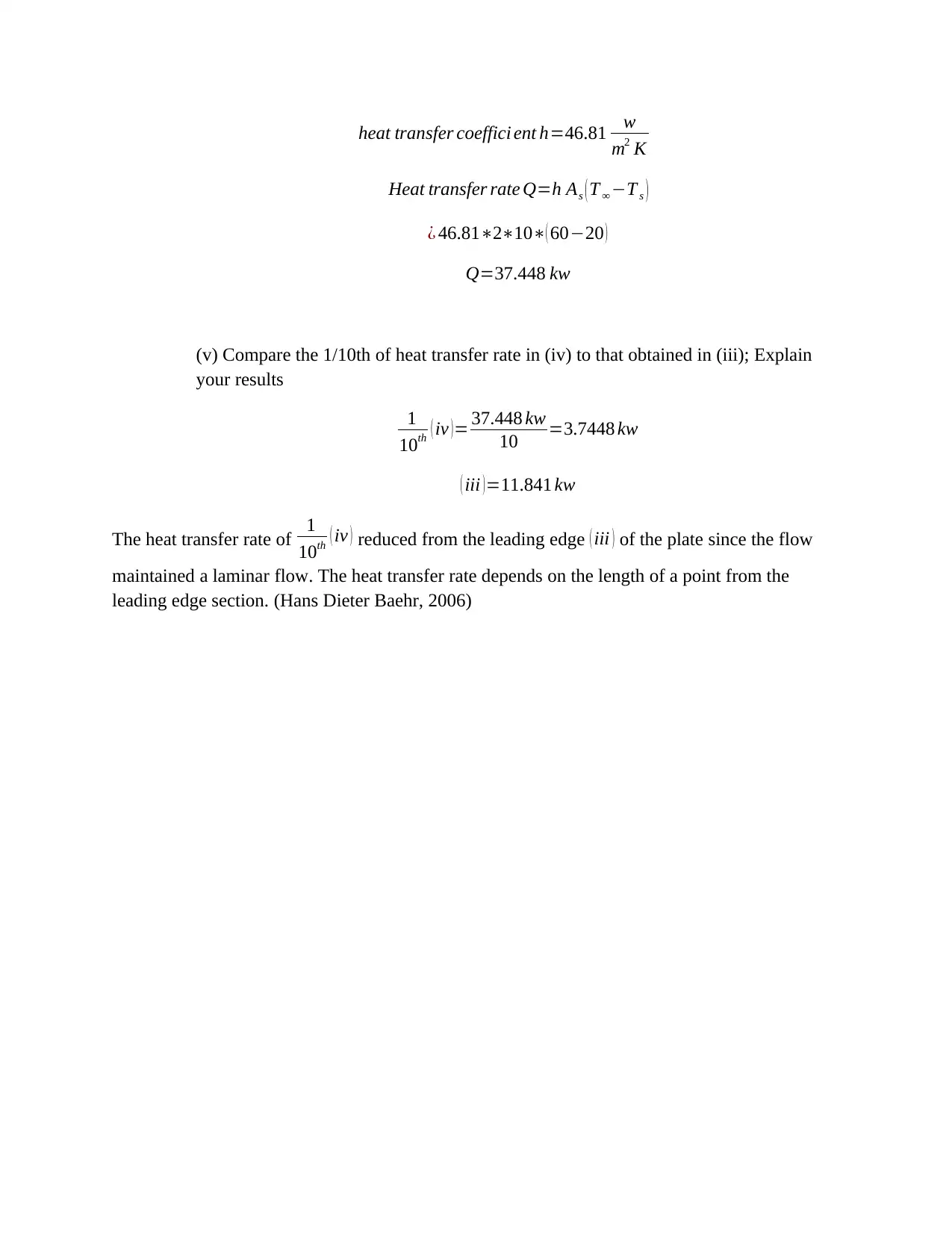
heat transfer coeffici ent h=46.81 w
m2 K
Heat transfer rate Q=h As ( T ∞ −T s )
¿ 46.81∗2∗10∗( 60−20 )
Q=37.448 kw
(v) Compare the 1/10th of heat transfer rate in (iv) to that obtained in (iii); Explain
your results
1
10th ( iv )= 37.448 kw
10 =3.7448 kw
( iii )=11.841 kw
The heat transfer rate of 1
10th ( iv ) reduced from the leading edge ( iii ) of the plate since the flow
maintained a laminar flow. The heat transfer rate depends on the length of a point from the
leading edge section. (Hans Dieter Baehr, 2006)

References
Hans Dieter Baehr, K. S. (2006). Heat and mass-transfer. Springer.
Theodore L. Bergman, A. S. (2011). Introduction to Heat Transfer, Sixth Edition . John Wiley & Sons, Inc.
Hans Dieter Baehr, K. S. (2006). Heat and mass-transfer. Springer.
Theodore L. Bergman, A. S. (2011). Introduction to Heat Transfer, Sixth Edition . John Wiley & Sons, Inc.
1 out of 18
Related Documents
Your All-in-One AI-Powered Toolkit for Academic Success.
+13062052269
info@desklib.com
Available 24*7 on WhatsApp / Email
![[object Object]](/_next/static/media/star-bottom.7253800d.svg)
Unlock your academic potential
© 2024 | Zucol Services PVT LTD | All rights reserved.


