A Physics Report on Heat Sinks and Their Performance Characteristics
VerifiedAdded on 2022/11/24
|20
|6005
|80
Report
AI Summary
This physics report delves into the performance characteristics of heat sinks, crucial components in electronic devices designed to dissipate excess heat. The study investigates various factors influencing heat dissipation, including the thermal conductivity of materials, heat sink shapes, and fluid dynamics (air, water, and refrigerants). It explores different cooling techniques such as forced air, liquid cooling (including nanofluids), heat pipes, and microchannels, comparing their effectiveness and efficiency. The report also discusses the impact of miniaturization in electronic devices, which has increased heat flux generation and the need for more advanced cooling solutions. The study includes an overview of stepwise activities, performance parameters, and case studies to distinguish between good and poor heat sink designs, emphasizing the importance of material selection, channel design, and fluid type for optimal heat extraction in CPUs and GPUs. The report further highlights the importance of cooling methods like heat pipes, heat pumps, spray cooling, and microchannels in modern electronics.
HEAT SINKS AND THEIR PERFORMANCE CHARACTERISTICS
A Physics Report on
Heat sinks and their performance characteristics
Submitted by
Student’s Name
To
Professor’s Name
Institution Affiliation
On
Date
A Physics Report on
Heat sinks and their performance characteristics
Submitted by
Student’s Name
To
Professor’s Name
Institution Affiliation
On
Date
Paraphrase This Document
Need a fresh take? Get an instant paraphrase of this document with our AI Paraphraser
HEAT SINKS AND THEIR PERFORMANCE CHARACTERISTICS
Heat sinks and their performance
characteristics
1. Abstract
The focus of this study is to investigate
the effect of heat transfer and flow performance
in multichannel heat sink base. The multiple
shapes under study will reveal the unexplored. It
is more likely to conclude that the combination of
the best material for conductivity and the efficient
channel would enhance the extraction of heat
through processing units. The idea of comparing
multiple densities and fluid type (Air, Water, and
Refrigerant R-123) is to consider the practical
aspect of large scale, low maintenance, low-cost
productivity. A detailed methodology with an
overview of stepwise activity and
results/performance parameters to be analyzed
have also been listed. The case studies
shortlisted along with a concoction of the
methodology will distinguish heat sinks of good
and poor designs. The study will reveal that the
heat dissipation characteristics of heat sinks are
always dependent on many factors, and these
factors always determine the overall efficiency of
the heat sinks. Some of these factors are the
thermal conductivity of materials used to
manufacture the heat sinks, the shapes of the
heat sinks, the velocity of the fluids used in the
heat sinks, the pressure of the fluids used in the
heat sinks, among many other factors.
Keywords:
Heat sink – A heat sink is a device whose main
function is absorbing and dissipating excess or
unwanted heat.
Thermal conductivity – This is the ability of a
material (matter) to conduct heat (thermal
energy).
CPU (Central processing unit) – This is one of
the major parts of the computer system and is
the part where almost all of the operations in a
computer system happen, generating a lot of
heat.
GPU (Graphical processing unit) – This is a
special electronic circuit in a computer system
which is designed to manipulate and change the
memory of the computer which then accelerates
the process of creating images, pictures, and
other graphics in a computer.
Thermal energy – This is also referred to as heat
energy and is the energy possessed by the
atoms or molecules of a substance (matter) after
being heated.
Convection – This is the process by which fluids
(liquid or air) is travels from one point to another
transferring some thermal energy after being
heated.
Nanofluids – Fluids which contain nano-sized
particles commonly referred to as nanoparticles.
2. Introduction
2
HEAT SINKS AND THEIR PERFORMANCE CHARACTERISTICS
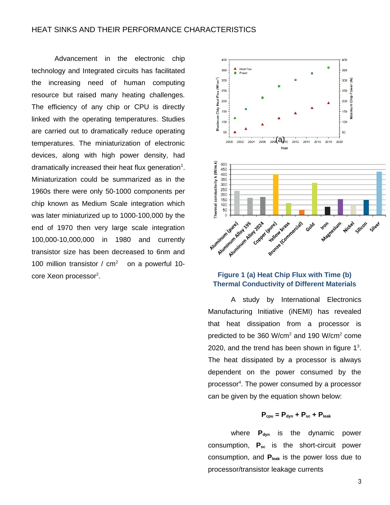
Advancement in the electronic chip
technology and Integrated circuits has facilitated
the increasing need of human computing
resource but raised many heating challenges.
The efficiency of any chip or CPU is directly
linked with the operating temperatures. Studies
are carried out to dramatically reduce operating
temperatures. The miniaturization of electronic
devices, along with high power density, had
dramatically increased their heat flux generation1.
Miniaturization could be summarized as in the
1960s there were only 50-1000 components per
chip known as Medium Scale integration which
was later miniaturized up to 1000-100,000 by the
end of 1970 then very large scale integration
100,000-10,000,000 in 1980 and currently
transistor size has been decreased to 6nm and
100 million transistor / cm2 on a powerful 10-
core Xeon processor2. Figure 1 (a) Heat Chip Flux with Time (b)
Thermal Conductivity of Different Materials
A study by International Electronics
Manufacturing Initiative (iNEMI) has revealed
that heat dissipation from a processor is
predicted to be 360 W/cm2 and 190 W/cm2 come
2020, and the trend has been shown in figure 13.
The heat dissipated by a processor is always
dependent on the power consumed by the
processor4. The power consumed by a processor
can be given by the equation shown below:
Pcpu = Pdyn + Psc + Pleak
where Pdyn is the dynamic power
consumption, Psc is the short-circuit power
consumption, and Pleak is the power loss due to
processor/transistor leakage currents
3
(a)
⊘ This is a preview!⊘
Do you want full access?
Subscribe today to unlock all pages.
Trusted by 1+ million students worldwide
HEAT SINKS AND THEIR PERFORMANCE CHARACTERISTICS
The dynamic power consumption can be
calculated using this formula:
Pdyn = CV2f
where C represents capacitance, V
represents voltage, and f represents frequency.
Nowadays, failure of electronic devices is
mainly due to overheating, and Pedram and
Nazarian demonstrated that more than 50% fail
because of thermal issues5. Lasance and
Simons’ study shows that heat flux of 100W/cm2
and to achieve the delta difference in
temperature of 50K requires heat (thermal)
transfer coefficient of 20,000W/m2, which is not
possible with force or free conventions of
coolants6. This increasing need would require
new methods to be developed or alternate way of
cooling and may not be manageable with
traditional cooling techniques. Conventional
cooling extraction methods mainly include forced
air and liquid cooling, free convection through
radiation or impinging jet with liquid evaporation.
The evaporation of liquid (forced convection) is
the most effective way as it can extract heat up
to 1000 kW/m2 as compared to forced convection
of air, which is only 10K kW/m2. Apart from
conventional techniques, the refrigerant cooling,
liquid cooling with nano-particles, microchannels,
heat pipes, heat pumps, thermo-siphons, and
spray cooling. Currently, heat pipes are widely
and efficiently used in laptops, computers
because of very low thermal resistance, i.e., 0.05
to 0.4oC/W7. Micro-channel-based cooling is also
very effective as it could extract heat and active
cooling of chips with an average power density of
400W/sq.cm8.
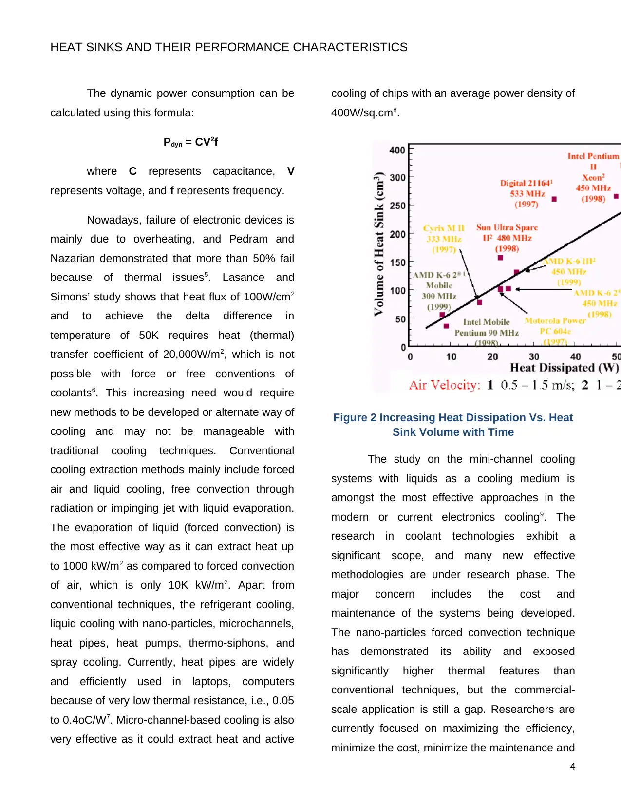
Figure 2 Increasing Heat Dissipation Vs. Heat
Sink Volume with Time
The study on the mini-channel cooling
systems with liquids as a cooling medium is
amongst the most effective approaches in the
modern or current electronics cooling9. The
research in coolant technologies exhibit a
significant scope, and many new effective
methodologies are under research phase. The
major concern includes the cost and
maintenance of the systems being developed.
The nano-particles forced convection technique
has demonstrated its ability and exposed
significantly higher thermal features than
conventional techniques, but the commercial-
scale application is still a gap. Researchers are
currently focused on maximizing the efficiency,
minimize the cost, minimize the maintenance and
4
The dynamic power consumption can be
calculated using this formula:
Pdyn = CV2f
where C represents capacitance, V
represents voltage, and f represents frequency.
Nowadays, failure of electronic devices is
mainly due to overheating, and Pedram and
Nazarian demonstrated that more than 50% fail
because of thermal issues5. Lasance and
Simons’ study shows that heat flux of 100W/cm2
and to achieve the delta difference in
temperature of 50K requires heat (thermal)
transfer coefficient of 20,000W/m2, which is not
possible with force or free conventions of
coolants6. This increasing need would require
new methods to be developed or alternate way of
cooling and may not be manageable with
traditional cooling techniques. Conventional
cooling extraction methods mainly include forced
air and liquid cooling, free convection through
radiation or impinging jet with liquid evaporation.
The evaporation of liquid (forced convection) is
the most effective way as it can extract heat up
to 1000 kW/m2 as compared to forced convection
of air, which is only 10K kW/m2. Apart from
conventional techniques, the refrigerant cooling,
liquid cooling with nano-particles, microchannels,
heat pipes, heat pumps, thermo-siphons, and
spray cooling. Currently, heat pipes are widely
and efficiently used in laptops, computers
because of very low thermal resistance, i.e., 0.05
to 0.4oC/W7. Micro-channel-based cooling is also
very effective as it could extract heat and active
cooling of chips with an average power density of
400W/sq.cm8.
Figure 2 Increasing Heat Dissipation Vs. Heat
Sink Volume with Time
The study on the mini-channel cooling
systems with liquids as a cooling medium is
amongst the most effective approaches in the
modern or current electronics cooling9. The
research in coolant technologies exhibit a
significant scope, and many new effective
methodologies are under research phase. The
major concern includes the cost and
maintenance of the systems being developed.
The nano-particles forced convection technique
has demonstrated its ability and exposed
significantly higher thermal features than
conventional techniques, but the commercial-
scale application is still a gap. Researchers are
currently focused on maximizing the efficiency,
minimize the cost, minimize the maintenance and
4
Paraphrase This Document
Need a fresh take? Get an instant paraphrase of this document with our AI Paraphraser
HEAT SINKS AND THEIR PERFORMANCE CHARACTERISTICS
easy to commercialize. The cost is a major factor
in any of the cooling product due to which a
combination of air cooling (fan) with a heat sink
or heat pipes had been a popular solution and
widely used for cooling of desktop computers /
CPUs. A recent development in the chip
technology has compacted and miniaturized
each component which dissipates heat as
compared to past where only CPUs were the
source and adequate cooling in only required for
the CPU10. Blowing of air with the fan was
sufficient, but now the more mass flow is needed
to overcome the heat sink convection resistance
and for better cooling. As the CPU power
continues to increase, more airflow is always
required to minimize the increasing heat-sink
convection resistance. Nowadays, CPU
manufacturers provide a datasheet for the
thermal design power (TDP) of a chip or
component for which cooling solution is to be
designed that would dissipate certain heat under
any workload. The TDP is not peak power but
used for a maximum of running application.
3. Different Types of Cooling Techniques
Before getting into design details, it is
convenient to discuss the different
conventional/modern cooling techniques that are
currently used in the cooling of CPUs. The
cooling modes are classified into four major
categories based on heat transfer effectiveness
and are given below:
1. Liquid evaporation (as in heat
pipes)
2. Forced air cooling using three or
multiple blade fans
3. Radiation and free convection
(heat pipe and heat sink)
4. Forced liquid cooling using
refrigerant, nanofluid, or any
other.
Also, the classification can be made
based on the cooling medium as listed below:
1. Refrigeration cooling (R12, R113,
R503, etc.)
2. Liquid cooling (Pump and liquid
coolant)
3. Air cooling (Using Blower / radial
fan)
Another widely used stratification is
based upon various emerging cooling methods.
The processor material adapted plays a major
role, and each one is further being researched
for better efficiency and effectiveness. The list of
such promising sources are as follows:
1. Heat pipes
2. Heat pumps
3. Spray cooling
4. Micro-channels
5. Phase change material (PCM)
which is based on cooling
6. Thermoelectric cooling
7. Free cooling
Various techniques currently being used
and researched will be reviewed in the next
subsections.
5
HEAT SINKS AND THEIR PERFORMANCE CHARACTERISTICS
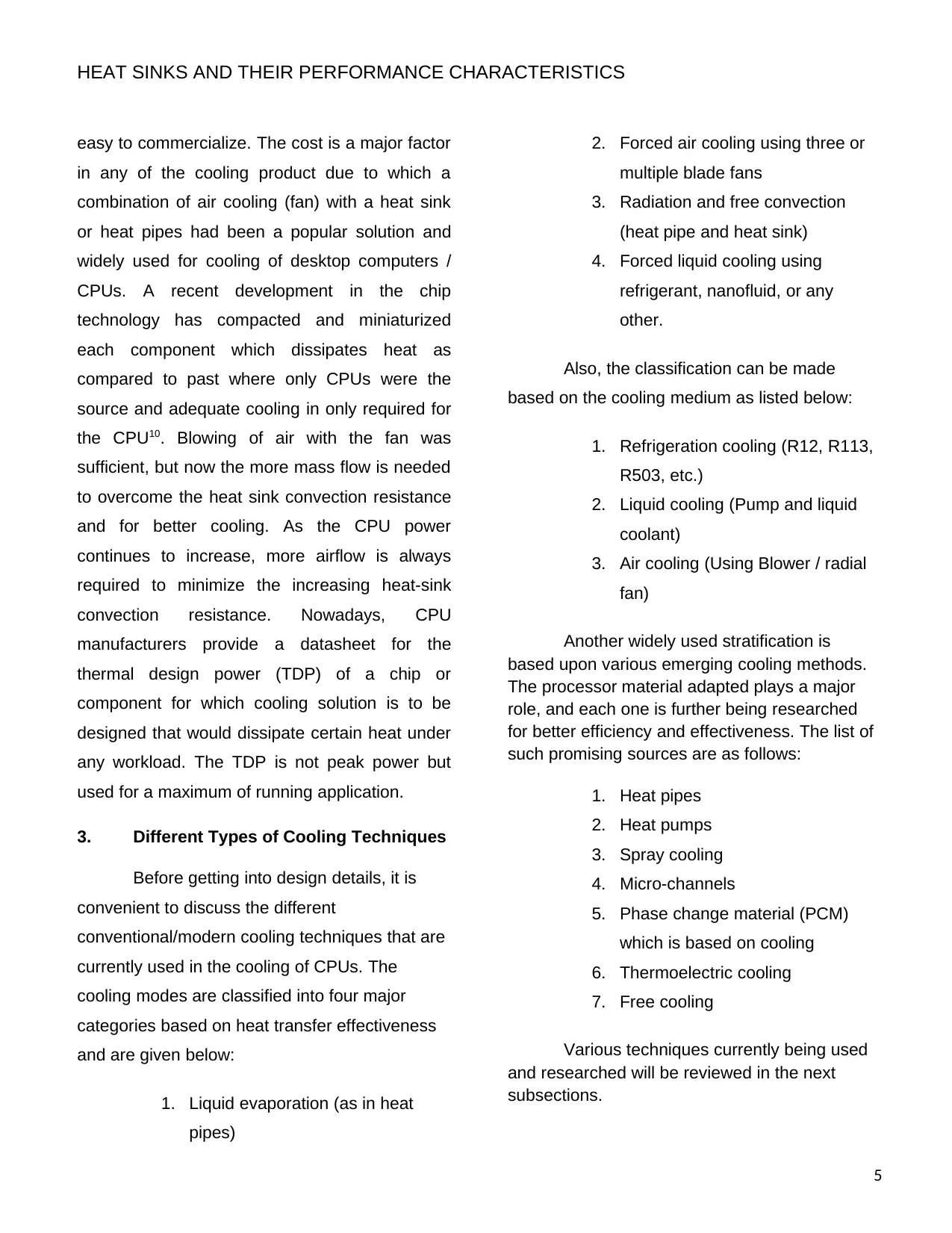
3.1. Heat Pipe
Heat Pipes are very efficient, effective and
possess high thermal conductivity (thousand
times better than the copper rod). It has
extremely low thermal resistance, which ranges
from 0.05 to about 0.4°C/ Watt. It is the most
viable and promising mean for cooling as it works
on heat transfer and phase transition effect. Its
broad use is mainly in electronic devices like
computers, telecommunication modules, satellite
electronics, and laptops. The major
categorization comes from the recent researches
and improvements which are given below:
1. Tubular (which includes the individual
micro heat pipes)
2. Flat plate (which includes vapour
chambers)
3. Direct contact systems heat pipe
4. Pulsating or Oscillating heat pipes
5. Microarray heat pipes
6. Thermo-syphons & loop heat pipes
Figure 3 Working Principle of Heat Pipe
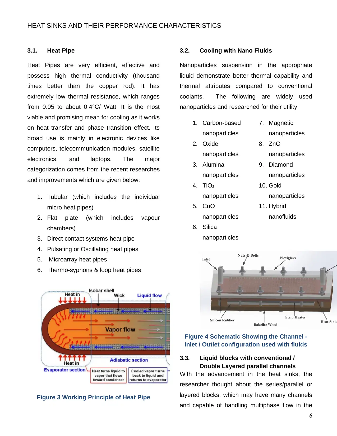
3.2. Cooling with Nano Fluids
Nanoparticles suspension in the appropriate
liquid demonstrate better thermal capability and
thermal attributes compared to conventional
coolants. The following are widely used
nanoparticles and researched for their utility
1. Carbon-based
nanoparticles
2. Oxide
nanoparticles
3. Alumina
nanoparticles
4. TiO2
nanoparticles
5. CuO
nanoparticles
6. Silica
nanoparticles
7. Magnetic
nanoparticles
8. ZnO
nanoparticles
9. Diamond
nanoparticles
10. Gold
nanoparticles
11. Hybrid
nanofluids
Figure 4 Schematic Showing the Channel -
Inlet / Outlet configuration used with fluids
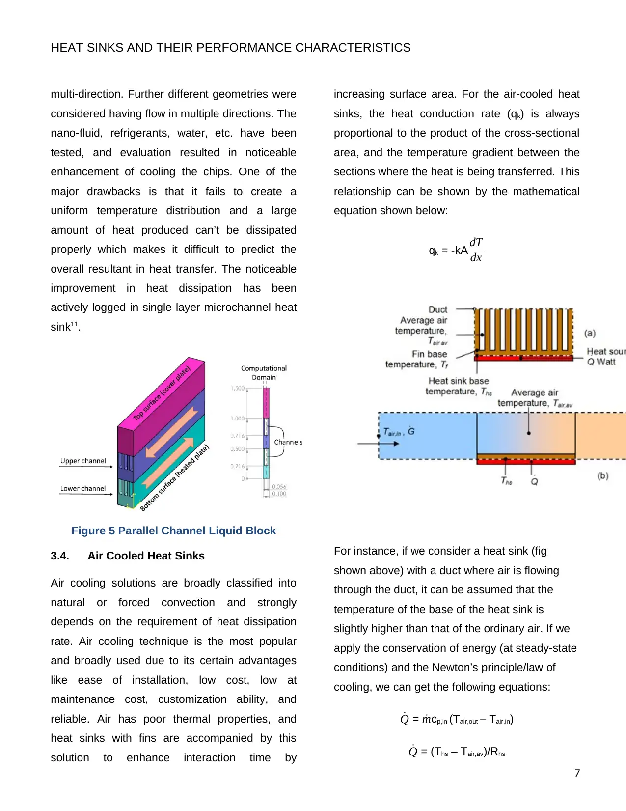
3.3. Liquid blocks with conventional /
Double Layered parallel channels
With the advancement in the heat sinks, the
researcher thought about the series/parallel or
layered blocks, which may have many channels
and capable of handling multiphase flow in the
6
3.1. Heat Pipe
Heat Pipes are very efficient, effective and
possess high thermal conductivity (thousand
times better than the copper rod). It has
extremely low thermal resistance, which ranges
from 0.05 to about 0.4°C/ Watt. It is the most
viable and promising mean for cooling as it works
on heat transfer and phase transition effect. Its
broad use is mainly in electronic devices like
computers, telecommunication modules, satellite
electronics, and laptops. The major
categorization comes from the recent researches
and improvements which are given below:
1. Tubular (which includes the individual
micro heat pipes)
2. Flat plate (which includes vapour
chambers)
3. Direct contact systems heat pipe
4. Pulsating or Oscillating heat pipes
5. Microarray heat pipes
6. Thermo-syphons & loop heat pipes
Figure 3 Working Principle of Heat Pipe
3.2. Cooling with Nano Fluids
Nanoparticles suspension in the appropriate
liquid demonstrate better thermal capability and
thermal attributes compared to conventional
coolants. The following are widely used
nanoparticles and researched for their utility
1. Carbon-based
nanoparticles
2. Oxide
nanoparticles
3. Alumina
nanoparticles
4. TiO2
nanoparticles
5. CuO
nanoparticles
6. Silica
nanoparticles
7. Magnetic
nanoparticles
8. ZnO
nanoparticles
9. Diamond
nanoparticles
10. Gold
nanoparticles
11. Hybrid
nanofluids
Figure 4 Schematic Showing the Channel -
Inlet / Outlet configuration used with fluids
3.3. Liquid blocks with conventional /
Double Layered parallel channels
With the advancement in the heat sinks, the
researcher thought about the series/parallel or
layered blocks, which may have many channels
and capable of handling multiphase flow in the
6
⊘ This is a preview!⊘
Do you want full access?
Subscribe today to unlock all pages.
Trusted by 1+ million students worldwide
HEAT SINKS AND THEIR PERFORMANCE CHARACTERISTICS
multi-direction. Further different geometries were
considered having flow in multiple directions. The
nano-fluid, refrigerants, water, etc. have been
tested, and evaluation resulted in noticeable
enhancement of cooling the chips. One of the
major drawbacks is that it fails to create a
uniform temperature distribution and a large
amount of heat produced can’t be dissipated
properly which makes it difficult to predict the
overall resultant in heat transfer. The noticeable
improvement in heat dissipation has been
actively logged in single layer microchannel heat
sink11.
Figure 5 Parallel Channel Liquid Block
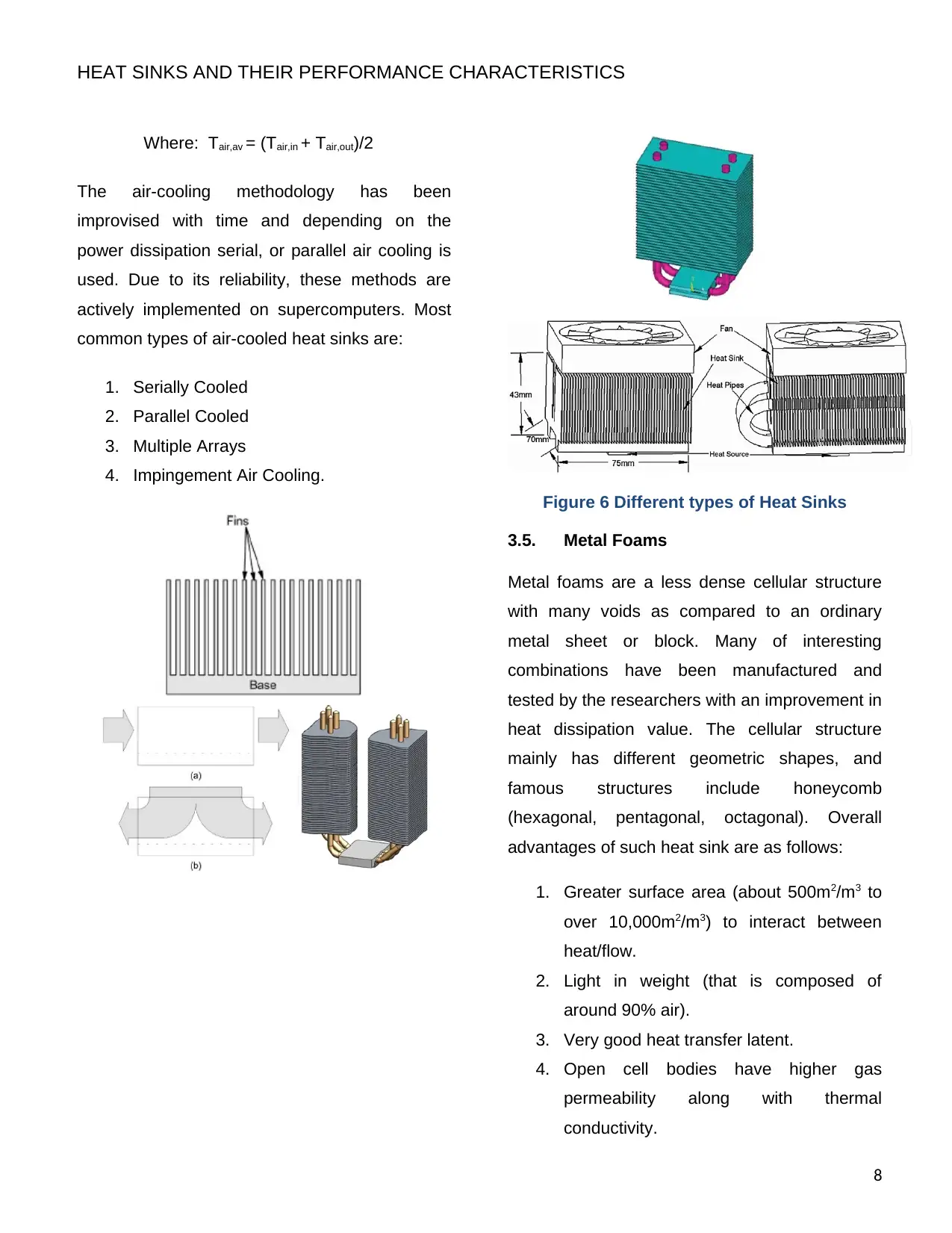
3.4. Air Cooled Heat Sinks
Air cooling solutions are broadly classified into
natural or forced convection and strongly
depends on the requirement of heat dissipation
rate. Air cooling technique is the most popular
and broadly used due to its certain advantages
like ease of installation, low cost, low at
maintenance cost, customization ability, and
reliable. Air has poor thermal properties, and
heat sinks with fins are accompanied by this
solution to enhance interaction time by
increasing surface area. For the air-cooled heat
sinks, the heat conduction rate (qk) is always
proportional to the product of the cross-sectional
area, and the temperature gradient between the
sections where the heat is being transferred. This
relationship can be shown by the mathematical
equation shown below:
qk = -kA dT
dx
For instance, if we consider a heat sink (fig
shown above) with a duct where air is flowing
through the duct, it can be assumed that the
temperature of the base of the heat sink is
slightly higher than that of the ordinary air. If we
apply the conservation of energy (at steady-state
conditions) and the Newton’s principle/law of
cooling, we can get the following equations:
˙Q = ˙mcp,in (Tair,out – Tair,in)
˙Q = (Ths – Tair,av)/Rhs
7
multi-direction. Further different geometries were
considered having flow in multiple directions. The
nano-fluid, refrigerants, water, etc. have been
tested, and evaluation resulted in noticeable
enhancement of cooling the chips. One of the
major drawbacks is that it fails to create a
uniform temperature distribution and a large
amount of heat produced can’t be dissipated
properly which makes it difficult to predict the
overall resultant in heat transfer. The noticeable
improvement in heat dissipation has been
actively logged in single layer microchannel heat
sink11.
Figure 5 Parallel Channel Liquid Block
3.4. Air Cooled Heat Sinks
Air cooling solutions are broadly classified into
natural or forced convection and strongly
depends on the requirement of heat dissipation
rate. Air cooling technique is the most popular
and broadly used due to its certain advantages
like ease of installation, low cost, low at
maintenance cost, customization ability, and
reliable. Air has poor thermal properties, and
heat sinks with fins are accompanied by this
solution to enhance interaction time by
increasing surface area. For the air-cooled heat
sinks, the heat conduction rate (qk) is always
proportional to the product of the cross-sectional
area, and the temperature gradient between the
sections where the heat is being transferred. This
relationship can be shown by the mathematical
equation shown below:
qk = -kA dT
dx
For instance, if we consider a heat sink (fig
shown above) with a duct where air is flowing
through the duct, it can be assumed that the
temperature of the base of the heat sink is
slightly higher than that of the ordinary air. If we
apply the conservation of energy (at steady-state
conditions) and the Newton’s principle/law of
cooling, we can get the following equations:
˙Q = ˙mcp,in (Tair,out – Tair,in)
˙Q = (Ths – Tair,av)/Rhs
7
Paraphrase This Document
Need a fresh take? Get an instant paraphrase of this document with our AI Paraphraser
HEAT SINKS AND THEIR PERFORMANCE CHARACTERISTICS
Where: Tair,av = (Tair,in + Tair,out)/2
The air-cooling methodology has been
improvised with time and depending on the
power dissipation serial, or parallel air cooling is
used. Due to its reliability, these methods are
actively implemented on supercomputers. Most
common types of air-cooled heat sinks are:
1. Serially Cooled
2. Parallel Cooled
3. Multiple Arrays
4. Impingement Air Cooling.
Figure 6 Different types of Heat Sinks
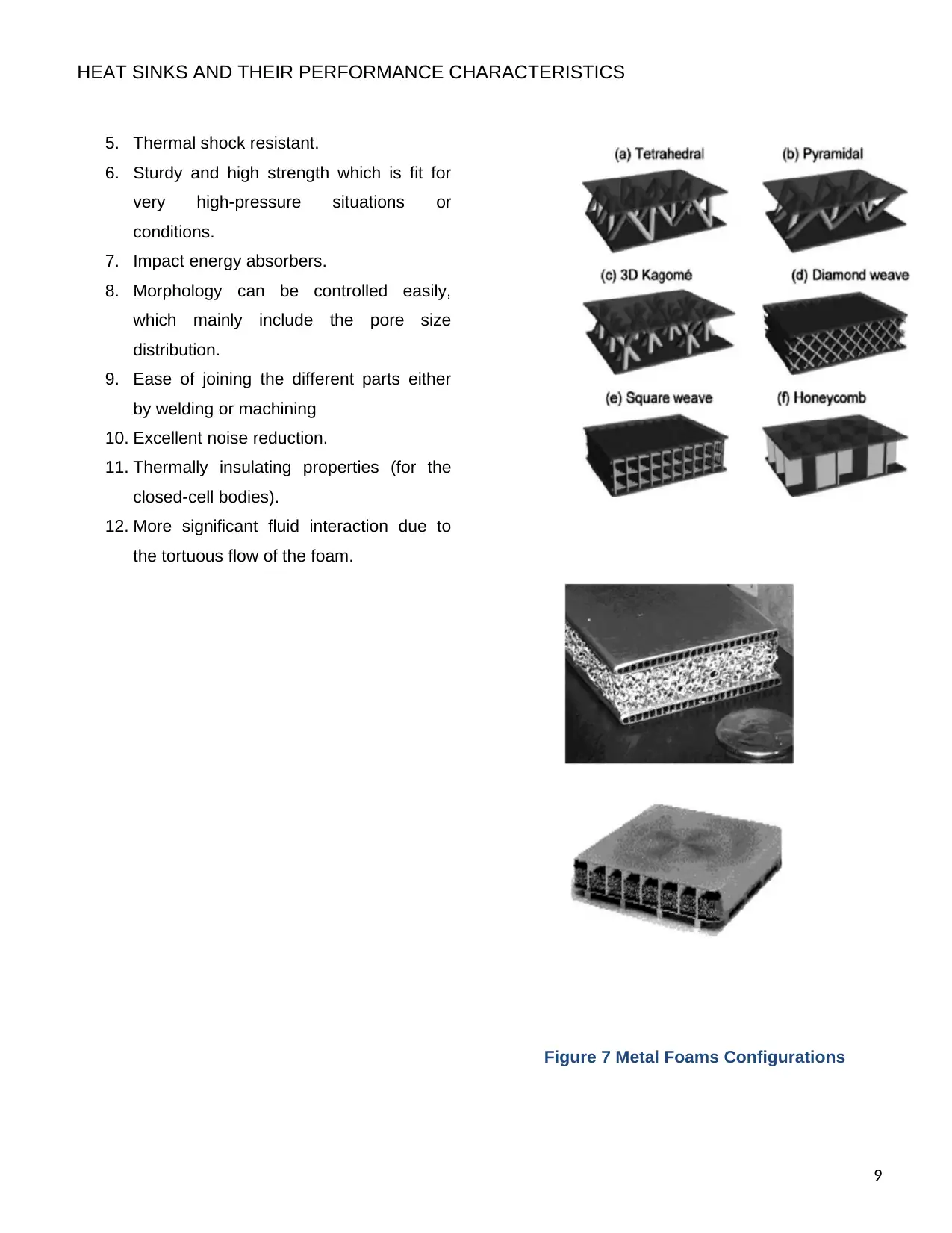
3.5. Metal Foams
Metal foams are a less dense cellular structure
with many voids as compared to an ordinary
metal sheet or block. Many of interesting
combinations have been manufactured and
tested by the researchers with an improvement in
heat dissipation value. The cellular structure
mainly has different geometric shapes, and
famous structures include honeycomb
(hexagonal, pentagonal, octagonal). Overall
advantages of such heat sink are as follows:
1. Greater surface area (about 500m2/m3 to
over 10,000m2/m3) to interact between
heat/flow.
2. Light in weight (that is composed of
around 90% air).
3. Very good heat transfer latent.
4. Open cell bodies have higher gas
permeability along with thermal
conductivity.
8
Where: Tair,av = (Tair,in + Tair,out)/2
The air-cooling methodology has been
improvised with time and depending on the
power dissipation serial, or parallel air cooling is
used. Due to its reliability, these methods are
actively implemented on supercomputers. Most
common types of air-cooled heat sinks are:
1. Serially Cooled
2. Parallel Cooled
3. Multiple Arrays
4. Impingement Air Cooling.
Figure 6 Different types of Heat Sinks
3.5. Metal Foams
Metal foams are a less dense cellular structure
with many voids as compared to an ordinary
metal sheet or block. Many of interesting
combinations have been manufactured and
tested by the researchers with an improvement in
heat dissipation value. The cellular structure
mainly has different geometric shapes, and
famous structures include honeycomb
(hexagonal, pentagonal, octagonal). Overall
advantages of such heat sink are as follows:
1. Greater surface area (about 500m2/m3 to
over 10,000m2/m3) to interact between
heat/flow.
2. Light in weight (that is composed of
around 90% air).
3. Very good heat transfer latent.
4. Open cell bodies have higher gas
permeability along with thermal
conductivity.
8
HEAT SINKS AND THEIR PERFORMANCE CHARACTERISTICS
5. Thermal shock resistant.
6. Sturdy and high strength which is fit for
very high-pressure situations or
conditions.
7. Impact energy absorbers.
8. Morphology can be controlled easily,
which mainly include the pore size
distribution.
9. Ease of joining the different parts either
by welding or machining
10. Excellent noise reduction.
11. Thermally insulating properties (for the
closed-cell bodies).
12. More significant fluid interaction due to
the tortuous flow of the foam.
Figure 7 Metal Foams Configurations
9
⊘ This is a preview!⊘
Do you want full access?
Subscribe today to unlock all pages.
Trusted by 1+ million students worldwide
HEAT SINKS AND THEIR PERFORMANCE CHARACTERISTICS
Thermal properties of metal foams with different
properties are given as under:
Material Dens
ity
(g/cm
3)
Thermal
conducti
vity
(W/m-K)
CTE
(μm/
m-K)
Specific
thermal
conducti
vity
(W/m-K)
Aluminu
m
Beryllium
Copper
Cu/l/Cu
Cu/Mo/
Cu
Cu/Mo-
Cu/Cu
Gold
Invar
Kovar
Lead
Molybde
num
Silver
Stainless
steel
Titanium
Tungsten
2.7
2.1
8.9
8.4
9.9
9.4
19.32
8.05
8.36
11
10.22
10.49
8.1
4.4
19.3
247
210
398
164
182
245-280
315
10
17
30
142
429
15.1
7.2
155
23
13.9
17
8.4
6.0
6.0-
10.0
14
1.6
5.1
39
4.9
18.9
17.3
9.5
4.5
91.5
10
44.7
19.5
18
26-30
16.3
1.2
2.0
2.7
13.9
40.9
1.9
1.6
8.0
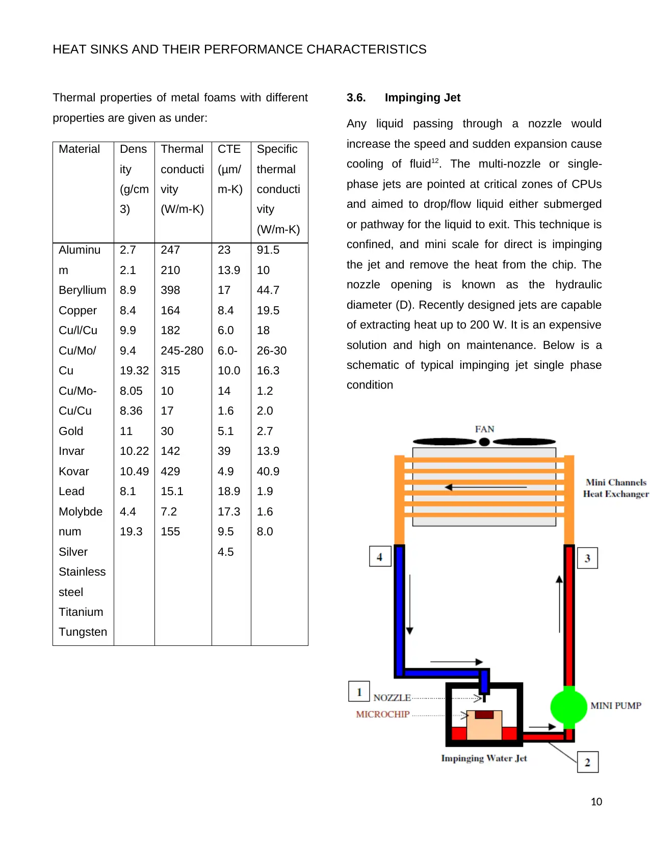
3.6. Impinging Jet
Any liquid passing through a nozzle would
increase the speed and sudden expansion cause
cooling of fluid12. The multi-nozzle or single-
phase jets are pointed at critical zones of CPUs
and aimed to drop/flow liquid either submerged
or pathway for the liquid to exit. This technique is
confined, and mini scale for direct is impinging
the jet and remove the heat from the chip. The
nozzle opening is known as the hydraulic
diameter (D). Recently designed jets are capable
of extracting heat up to 200 W. It is an expensive
solution and high on maintenance. Below is a
schematic of typical impinging jet single phase
condition
10
Thermal properties of metal foams with different
properties are given as under:
Material Dens
ity
(g/cm
3)
Thermal
conducti
vity
(W/m-K)
CTE
(μm/
m-K)
Specific
thermal
conducti
vity
(W/m-K)
Aluminu
m
Beryllium
Copper
Cu/l/Cu
Cu/Mo/
Cu
Cu/Mo-
Cu/Cu
Gold
Invar
Kovar
Lead
Molybde
num
Silver
Stainless
steel
Titanium
Tungsten
2.7
2.1
8.9
8.4
9.9
9.4
19.32
8.05
8.36
11
10.22
10.49
8.1
4.4
19.3
247
210
398
164
182
245-280
315
10
17
30
142
429
15.1
7.2
155
23
13.9
17
8.4
6.0
6.0-
10.0
14
1.6
5.1
39
4.9
18.9
17.3
9.5
4.5
91.5
10
44.7
19.5
18
26-30
16.3
1.2
2.0
2.7
13.9
40.9
1.9
1.6
8.0
3.6. Impinging Jet
Any liquid passing through a nozzle would
increase the speed and sudden expansion cause
cooling of fluid12. The multi-nozzle or single-
phase jets are pointed at critical zones of CPUs
and aimed to drop/flow liquid either submerged
or pathway for the liquid to exit. This technique is
confined, and mini scale for direct is impinging
the jet and remove the heat from the chip. The
nozzle opening is known as the hydraulic
diameter (D). Recently designed jets are capable
of extracting heat up to 200 W. It is an expensive
solution and high on maintenance. Below is a
schematic of typical impinging jet single phase
condition
10
Paraphrase This Document
Need a fresh take? Get an instant paraphrase of this document with our AI Paraphraser
HEAT SINKS AND THEIR PERFORMANCE CHARACTERISTICS
Figure 8 Impinging Jet
3.7. Others
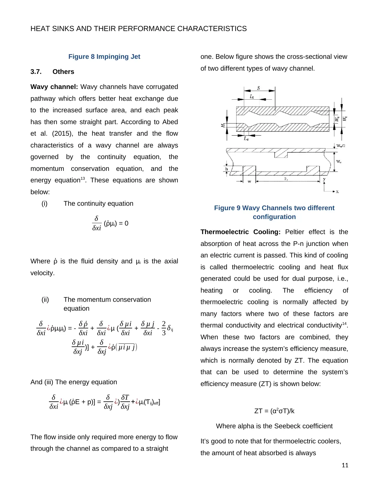
Wavy channel: Wavy channels have corrugated
pathway which offers better heat exchange due
to the increased surface area, and each peak
has then some straight part. According to Abed
et al. (2015), the heat transfer and the flow
characteristics of a wavy channel are always
governed by the continuity equation, the
momentum conservation equation, and the
energy equation13. These equations are shown
below:
(i) The continuity equation
δ
δxi (ῥμi) = 0
Where ῥ is the fluid density and μi is the axial
velocity.
(ii) The momentum conservation
equation
δ
δxi ¿ῥμiμj) = - δ ῥ
δxi + δ
δxi ¿μ ( δ μi
δxi + δ μ j
δxi - 2
3 δij
δ μi
δxj )] + δ
δxj ¿ῥ( μi μ j)
And (iii) The energy equation
δ
δxi ¿μi (ῥE + p)] = δ
δxj ¿) δT
δxj +¿μi(Ƭij)eff]
The flow inside only required more energy to flow
through the channel as compared to a straight
one. Below figure shows the cross-sectional view
of two different types of wavy channel.
Figure 9 Wavy Channels two different
configuration
Thermoelectric Cooling: Peltier effect is the
absorption of heat across the P-n junction when
an electric current is passed. This kind of cooling
is called thermoelectric cooling and heat flux
generated could be used for dual purpose, i.e.,
heating or cooling. The efficiency of
thermoelectric cooling is normally affected by
many factors where two of these factors are
thermal conductivity and electrical conductivity14.
When these two factors are combined, they
always increase the system’s efficiency measure,
which is normally denoted by ZT. The equation
that can be used to determine the system’s
efficiency measure (ZT) is shown below:
ZT = (α2σT)/k
Where alpha is the Seebeck coefficient
It’s good to note that for thermoelectric coolers,
the amount of heat absorbed is always
11
Figure 8 Impinging Jet
3.7. Others
Wavy channel: Wavy channels have corrugated
pathway which offers better heat exchange due
to the increased surface area, and each peak
has then some straight part. According to Abed
et al. (2015), the heat transfer and the flow
characteristics of a wavy channel are always
governed by the continuity equation, the
momentum conservation equation, and the
energy equation13. These equations are shown
below:
(i) The continuity equation
δ
δxi (ῥμi) = 0
Where ῥ is the fluid density and μi is the axial
velocity.
(ii) The momentum conservation
equation
δ
δxi ¿ῥμiμj) = - δ ῥ
δxi + δ
δxi ¿μ ( δ μi
δxi + δ μ j
δxi - 2
3 δij
δ μi
δxj )] + δ
δxj ¿ῥ( μi μ j)
And (iii) The energy equation
δ
δxi ¿μi (ῥE + p)] = δ
δxj ¿) δT
δxj +¿μi(Ƭij)eff]
The flow inside only required more energy to flow
through the channel as compared to a straight
one. Below figure shows the cross-sectional view
of two different types of wavy channel.
Figure 9 Wavy Channels two different
configuration
Thermoelectric Cooling: Peltier effect is the
absorption of heat across the P-n junction when
an electric current is passed. This kind of cooling
is called thermoelectric cooling and heat flux
generated could be used for dual purpose, i.e.,
heating or cooling. The efficiency of
thermoelectric cooling is normally affected by
many factors where two of these factors are
thermal conductivity and electrical conductivity14.
When these two factors are combined, they
always increase the system’s efficiency measure,
which is normally denoted by ZT. The equation
that can be used to determine the system’s
efficiency measure (ZT) is shown below:
ZT = (α2σT)/k
Where alpha is the Seebeck coefficient
It’s good to note that for thermoelectric coolers,
the amount of heat absorbed is always
11
HEAT SINKS AND THEIR PERFORMANCE CHARACTERISTICS
proportional to the time and current passing
through the coolers. Mathematically, this
relationship can be represented by the equation
below:
Q = Pit
Where Q is the heat absorbed, P is the Peltier
coefficient, I is the current passing through the
thermoelectric cooler, and t is the time
Figure 10 P-n Type Solid State Material for
Thermoelectric Cooling
4. Methodology
To numerically investigate the effect of
the heat exchange rate in a heat sink having
channels parallel to chip. The channels with
different profile effect on heat transfer
effectiveness or the coefficient of performance
will be studied at different velocities. The most
appropriate and efficient would be selected
based on flow and heat properties. The case
study will start by analyzing air, water, and
refrigerant R-123 through circular cross-sectional
tubes and later analyzing on all the star shapes.
The star shapes with three, five, seven, nine, and
twelve fins will be simulated afterwards. The
hybrid cooling system contains different fluid
flowing through the heat sink. The hybrid cooling
system will mainly comprise of air channels,
refrigerant channel, and coolant (liquid)
channels15.
Figure 11 Methodology
12
CPU BASE DIMENSIONS
CPU THERMAL DESIGN
POWER (TDP)
TARGET COOLING
TEMPERATURE
MATERIAL FOR HEAT
SINK (W/Mk & DENSITY)
INLET VELOCITY (0.5,
2.5, & 5m/s)
CPU BASE
TEMPERATURE (K)
GEOMETRY/MODEL
MESHING
BOUNDARY CONDITIONS
ANALYSIS
RESULTS
COMPARISON
V=0.5m/s
⊘ This is a preview!⊘
Do you want full access?
Subscribe today to unlock all pages.
Trusted by 1+ million students worldwide
1 out of 20
Related Documents


Your All-in-One AI-Powered Toolkit for Academic Success.
+13062052269
info@desklib.com
Available 24*7 on WhatsApp / Email
![[object Object]](/_next/static/media/star-bottom.7253800d.svg)
Unlock your academic potential
Copyright © 2020–2026 A2Z Services. All Rights Reserved. Developed and managed by ZUCOL.