Hydraulic for Civil Engineering | Report
VerifiedAdded on 2022/08/13
|12
|2268
|34
AI Summary
Contribute Materials
Your contribution can guide someone’s learning journey. Share your
documents today.
Hydraulic for civil engineering
Introduction
Distribution system of fresh water would have various infrastructures that include collections,
treatment, transmission, storage and distribution to various sectors. The system of water would
always be required to meet commercial, public and industrial activities. The supplied water
would fulfilled both quantity and quality requirements.
Human life is dependent on water as is the case with all animal and plant life on the planet. We
need water for growing food, generation of power, running of factories and generally we require
water as a vital part of our daily lives. About 70 liters of basic needs per person per day would
require water. This requires the need for water to ensure a basic personal standards and
household hygiene sufficient for health maintenance. The consequences of insufficient water
supply would cause disease, energy and time expected on routine collection. .
The process of distributing water in each and every section of a given region would attract
various factors that always would be considered. To prevent obstacles that might be encountered
by the water being transported, measurements of the water rate, the size of the pipes and the open
channel, the slope of the floor, the pressure exerted and the factors that could cause water flow
resistance would be determined and their effectiveness ensured.
The system of fluid flow head loss components would include friction loss conduit loss through
their fittings like tee, elbows valves and reducers. These types of losses normally would be
classified as minor loss while major loss incorporates significant multiplicity of fittings.
Objectives
The main goals which would be reached at the end of the study would include
1. To assess problems with hydrostatics and hydrodynamics
2. To determining the forces exerted on resting fluids and in motion
3. To determining appropriate water distribution pipe sizes
4. To assess the hydrostatic pressure on substructures that would be exerted.
5.
Secure Best Marks with AI Grader
Need help grading? Try our AI Grader for instant feedback on your assignments.
Calculations
Task 1
ai) Pressure in the pipe
Given:
Height = 100 m
Pressure = ρ * g * h
Where,
Density of water = 1000 kg/m3
g = 9.81 N/kg
Pressure = 9.81 * 1000 * 100
= 981,000 N/m2
1 bar = 100000 N/m2
Representing the vaklues in bar
= 981,000/100000
= 9.81 bar
ii) Pressure in the open channel
Given:
Height = 100 m
Pressure = ρ * g * h
Where,
Density of water = 1000 kg/m3
g = 9.81 N/kg
Pressure = 9.81 * 1000 * 100
= 981,000 N/m2
1 bar = 100000 N/m2
Representing the vaklues in bar
= 981,000/100000
= 9.81 b
Pressure is equivalent to force per unit area and in liquid it be would be presented as, P = ρ * g *
h, pressure in this case from the calculation would be equivalent the reason being all the variable
amounts are maintained.
b) Types of forces that resists water flow in pipes
i) Viscosity
Viscosity refers to the measure of resistance of the fluid that flows. The resisistance of the fluid
flow in pipes would be as a result of the existence of internal friction. Large internal friction
would be produced when the fluid that flows would have large viscosity. Furthermore, less
internal friction would be produced when the fluid that flows through the pipe would have low
visicosity (Jha, Cueto-Felgueroso and Juanes, 2011).
ii) Boundaries
Thick boundary layers would increase the shear stress that would resist the flow of the liquid in
the pipes, similarly the thin boundary would decrease the shear stress that would partially resist
the flow of the liquid in the pipes. .
c) Effects of water temperatures on forces that resists water flow in pipes
High temperatures of water impact the structure of water molecules and in the process it enable
the molecules to move fast and overcome the binding forces of the water molecules, therefore
reducing both viscosity and boundary layers (Aladag et al., 2012).
d) Difference between laminar and turbulent flow
The following are differences between laminar and turbulent (Massey, Bernards and Ward-
Smith, 2012)
Laminar flow Turbulent flow
The fluid layers do not cross each other
because they move parallel
The fluid layers cross each other since they do
not move parallel
It would occur in small size pipes and when
velocity of flow would be low
It would occur in large size pipes and when
velocity of flow would be high
The Reynold’s number ≤ 2000 The Reynold’s number ≥ 4000
e) Reynolds number and its relation to turbulent flow
Reynolds number is defined as the product of length times velocity times density divided by the
coefficient of viscosity (Qian et al., 2012).
This would be represented as;
Re = V avg D
v = ρV avg D
μ
Where,
Vavg = average velocity
D = diameter
v = μ
ρ = kinematic velocity
The flow in pipes would be turbulent for Re ≥ 4000
f) Boundary layer and how it is affected by water flow surface roughness
Boundary layer is defined as a comparatively thin fluid layer near a body’s surface submerged in
a fluid flow.
As the laminar layer of roughness grows in thickness, it becomes unstable and can then
be converted into a turbulent boundary layer where the fluid particles begin to move
haphazardly.
g) Reduction of water flow resistance in pipes and open channel
Reducing viscosity would reduce water flow resistance both in open channel and pipes through
reducing the friction between water and surface. This would also result in low shear stress to a
body as the water flows through it.
h) Methods involved in supply addition water in town without disrupting the current
water supply
Increase in water supply would be piped in the city if more and larger water reservoirs were
installed and the water they supply directed towards the initial distribution of pipes. Increased
number of reservoirs would mean that more water would be supplied while maintaining the
initial distribution pipes would means that there would be no water supply disruptions.
Task 2
a) Calculation of maximum depth of flow using Manning formula
Open channel
Secure Best Marks with AI Grader
Need help grading? Try our AI Grader for instant feedback on your assignments.
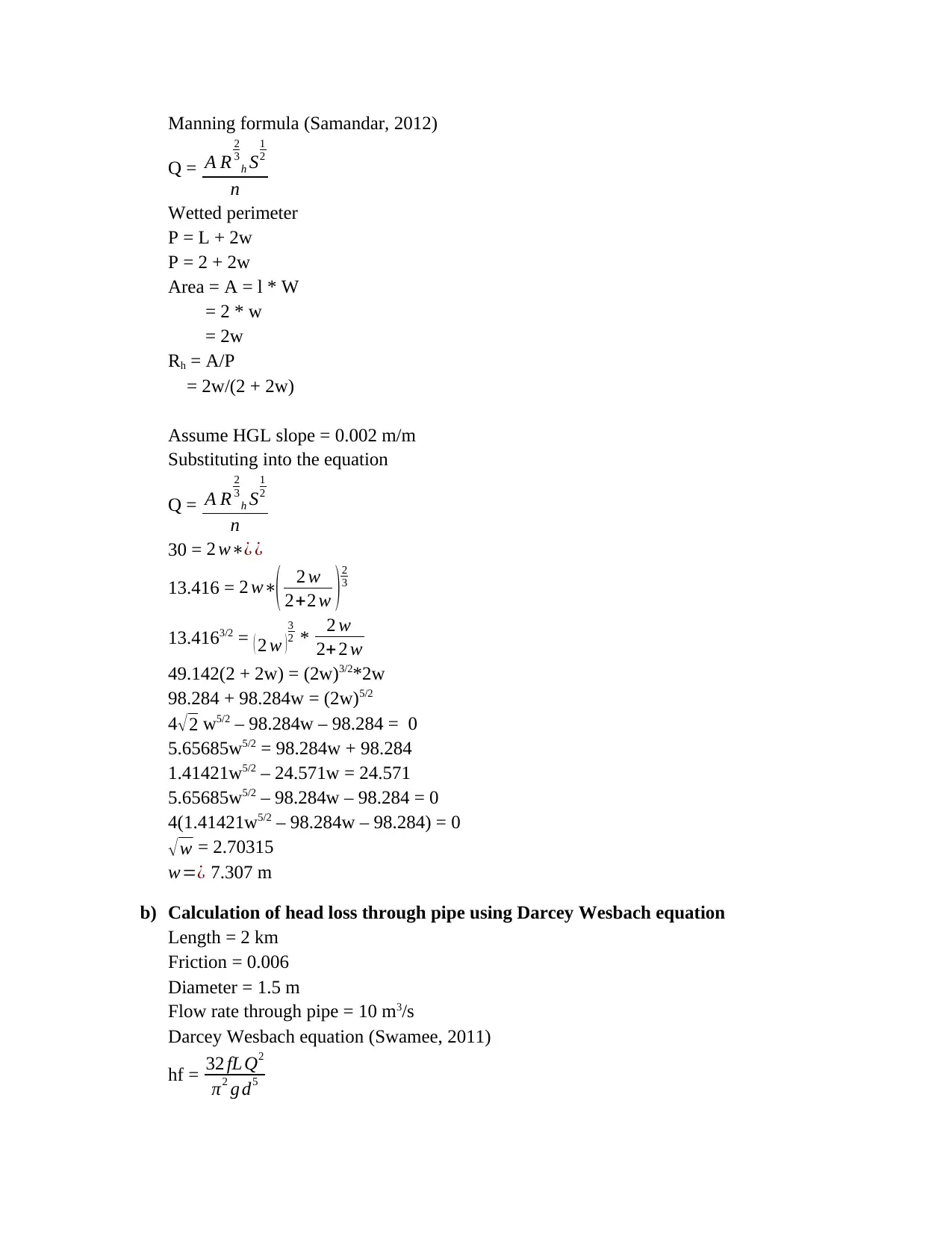
Manning formula (Samandar, 2012)
Q = A R
2
3
h S
1
2
n
Wetted perimeter
P = L + 2w
P = 2 + 2w
Area = A = l * W
= 2 * w
= 2w
Rh = A/P
= 2w/(2 + 2w)
Assume HGL slope = 0.002 m/m
Substituting into the equation
Q = A R
2
3
h S
1
2
n
30 = 2 w∗¿ ¿
13.416 = 2 w∗( 2 w
2+2 w )2
3
13.4163/2 = ( 2 w )
3
2 * 2 w
2+ 2 w
49.142(2 + 2w) = (2w)3/2*2w
98.284 + 98.284w = (2w)5/2
4√2 w5/2 – 98.284w – 98.284 = 0
5.65685w5/2 = 98.284w + 98.284
1.41421w5/2 – 24.571w = 24.571
5.65685w5/2 – 98.284w – 98.284 = 0
4(1.41421w5/2 – 98.284w – 98.284) = 0
√ w = 2.70315
w=¿ 7.307 m
b) Calculation of head loss through pipe using Darcey Wesbach equation
Length = 2 km
Friction = 0.006
Diameter = 1.5 m
Flow rate through pipe = 10 m3/s
Darcey Wesbach equation (Swamee, 2011)
hf = 32 fL Q2
π2 g d5
Q = A R
2
3
h S
1
2
n
Wetted perimeter
P = L + 2w
P = 2 + 2w
Area = A = l * W
= 2 * w
= 2w
Rh = A/P
= 2w/(2 + 2w)
Assume HGL slope = 0.002 m/m
Substituting into the equation
Q = A R
2
3
h S
1
2
n
30 = 2 w∗¿ ¿
13.416 = 2 w∗( 2 w
2+2 w )2
3
13.4163/2 = ( 2 w )
3
2 * 2 w
2+ 2 w
49.142(2 + 2w) = (2w)3/2*2w
98.284 + 98.284w = (2w)5/2
4√2 w5/2 – 98.284w – 98.284 = 0
5.65685w5/2 = 98.284w + 98.284
1.41421w5/2 – 24.571w = 24.571
5.65685w5/2 – 98.284w – 98.284 = 0
4(1.41421w5/2 – 98.284w – 98.284) = 0
√ w = 2.70315
w=¿ 7.307 m
b) Calculation of head loss through pipe using Darcey Wesbach equation
Length = 2 km
Friction = 0.006
Diameter = 1.5 m
Flow rate through pipe = 10 m3/s
Darcey Wesbach equation (Swamee, 2011)
hf = 32 fL Q2
π2 g d5
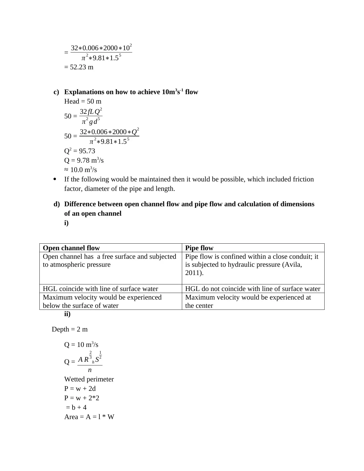
= 32∗0.006∗2000∗102
π 2∗9.81∗1.55
= 52.23 m
c) Explanations on how to achieve 10m3s-1 flow
Head = 50 m
50 = 32 fL Q2
π2 g d5
50 = 32∗0.006∗2000∗Q2
π 2∗9.81∗1.55
Q2 = 95.73
Q = 9.78 m3/s
≈ 10.0 m3/s
If the following would be maintained then it would be possible, which included friction
factor, diameter of the pipe and length.
d) Difference between open channel flow and pipe flow and calculation of dimensions
of an open channel
i)
Open channel flow Pipe flow
Open channel has a free surface and subjected
to atmospheric pressure
Pipe flow is confined within a close conduit; it
is subjected to hydraulic pressure (Avila,
2011).
HGL coincide with line of surface water HGL do not coincide with line of surface water
Maximum velocity would be experienced
below the surface of water
Maximum velocity would be experienced at
the center
ii)
Depth = 2 m
Q = 10 m3/s
Q = A R
2
3
h S
1
2
n
Wetted perimeter
P = w + 2d
P = w + 2*2
= b + 4
Area = A = l * W
π 2∗9.81∗1.55
= 52.23 m
c) Explanations on how to achieve 10m3s-1 flow
Head = 50 m
50 = 32 fL Q2
π2 g d5
50 = 32∗0.006∗2000∗Q2
π 2∗9.81∗1.55
Q2 = 95.73
Q = 9.78 m3/s
≈ 10.0 m3/s
If the following would be maintained then it would be possible, which included friction
factor, diameter of the pipe and length.
d) Difference between open channel flow and pipe flow and calculation of dimensions
of an open channel
i)
Open channel flow Pipe flow
Open channel has a free surface and subjected
to atmospheric pressure
Pipe flow is confined within a close conduit; it
is subjected to hydraulic pressure (Avila,
2011).
HGL coincide with line of surface water HGL do not coincide with line of surface water
Maximum velocity would be experienced
below the surface of water
Maximum velocity would be experienced at
the center
ii)
Depth = 2 m
Q = 10 m3/s
Q = A R
2
3
h S
1
2
n
Wetted perimeter
P = w + 2d
P = w + 2*2
= b + 4
Area = A = l * W
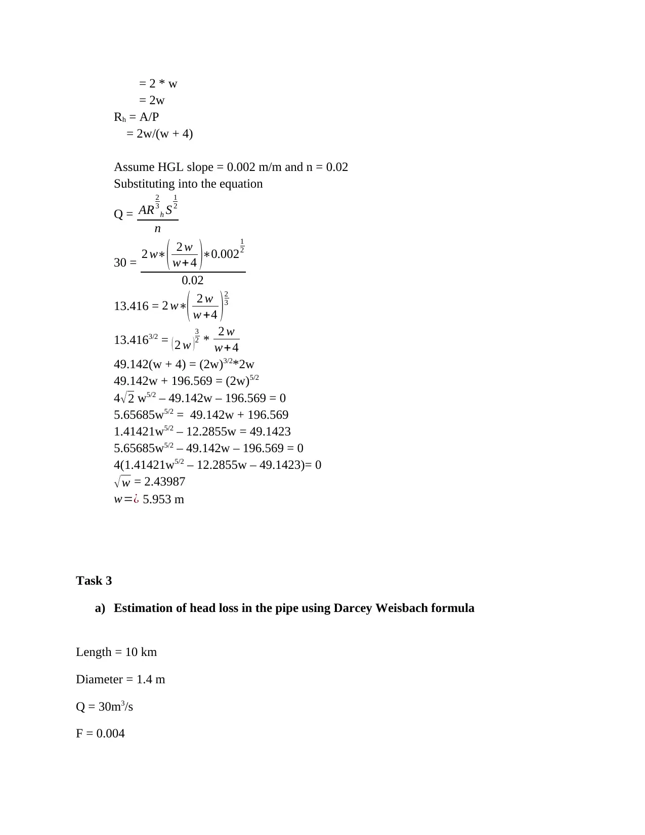
= 2 * w
= 2w
Rh = A/P
= 2w/(w + 4)
Assume HGL slope = 0.002 m/m and n = 0.02
Substituting into the equation
Q = AR
2
3
h S
1
2
n
30 = 2 w∗( 2 w
w+ 4 )∗0.002
1
2
0.02
13.416 = 2 w∗( 2 w
w +4 ) 2
3
13.4163/2 = ( 2 w )
3
2 * 2 w
w+ 4
49.142(w + 4) = (2w)3/2*2w
49.142w + 196.569 = (2w)5/2
4√2 w5/2 – 49.142w – 196.569 = 0
5.65685w5/2 = 49.142w + 196.569
1.41421w5/2 – 12.2855w = 49.1423
5.65685w5/2 – 49.142w – 196.569 = 0
4(1.41421w5/2 – 12.2855w – 49.1423)= 0
√ w = 2.43987
w=¿ 5.953 m
Task 3
a) Estimation of head loss in the pipe using Darcey Weisbach formula
Length = 10 km
Diameter = 1.4 m
Q = 30m3/s
F = 0.004
Paraphrase This Document
Need a fresh take? Get an instant paraphrase of this document with our AI Paraphraser
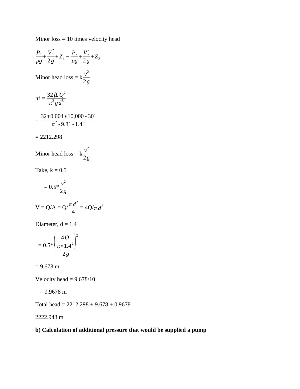
Minor loss = 10 times velocity head
P1
ρg + V 1
2
2 g + Z1 = P2
ρg + V 2
2
2 g + Z2
Minor head loss = k v2
2 g
hf = 32 fL Q2
π2 g d5
= 32∗0.004∗10,000∗302
π2∗9.81∗1.45
= 2212.298
Minor head loss = k v2
2 g
Take, k = 0.5
= 0.5* v2
2 g
V = Q/A = Q/ π d2
4 = 4Q/ π d2
Diameter, d = 1.4
= 0.5* ( 4 Q
π∗1.42 )
2
2 g
= 9.678 m
Velocity head = 9.678/10
= 0.9678 m
Total head = 2212.298 + 9.678 + 0.9678
2222.943 m
b) Calculation of additional pressure that would be supplied a pump
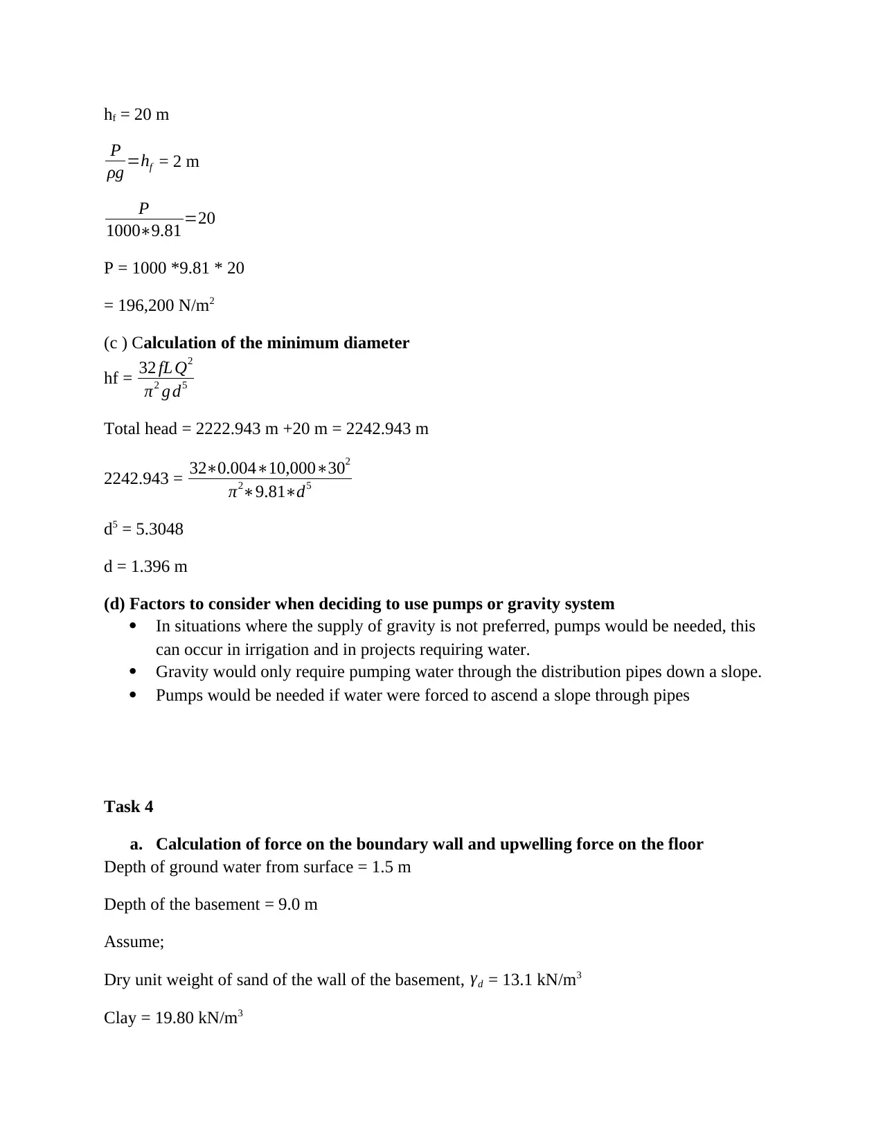
hf = 20 m
P
ρg =hf = 2 m
P
1000∗9.81 =20
P = 1000 *9.81 * 20
= 196,200 N/m2
(c ) Calculation of the minimum diameter
hf = 32 fL Q2
π2 g d5
Total head = 2222.943 m +20 m = 2242.943 m
2242.943 = 32∗0.004∗10,000∗302
π2∗9.81∗d5
d5 = 5.3048
d = 1.396 m
(d) Factors to consider when deciding to use pumps or gravity system
In situations where the supply of gravity is not preferred, pumps would be needed, this
can occur in irrigation and in projects requiring water.
Gravity would only require pumping water through the distribution pipes down a slope.
Pumps would be needed if water were forced to ascend a slope through pipes
Task 4
a. Calculation of force on the boundary wall and upwelling force on the floor
Depth of ground water from surface = 1.5 m
Depth of the basement = 9.0 m
Assume;
Dry unit weight of sand of the wall of the basement, γd = 13.1 kN/m3
Clay = 19.80 kN/m3
P
ρg =hf = 2 m
P
1000∗9.81 =20
P = 1000 *9.81 * 20
= 196,200 N/m2
(c ) Calculation of the minimum diameter
hf = 32 fL Q2
π2 g d5
Total head = 2222.943 m +20 m = 2242.943 m
2242.943 = 32∗0.004∗10,000∗302
π2∗9.81∗d5
d5 = 5.3048
d = 1.396 m
(d) Factors to consider when deciding to use pumps or gravity system
In situations where the supply of gravity is not preferred, pumps would be needed, this
can occur in irrigation and in projects requiring water.
Gravity would only require pumping water through the distribution pipes down a slope.
Pumps would be needed if water were forced to ascend a slope through pipes
Task 4
a. Calculation of force on the boundary wall and upwelling force on the floor
Depth of ground water from surface = 1.5 m
Depth of the basement = 9.0 m
Assume;
Dry unit weight of sand of the wall of the basement, γd = 13.1 kN/m3
Clay = 19.80 kN/m3
Total stress = γd h+ γt , sand h1 +γsat , clay h2
= 13.1 *1.5 + 7.5 *19.80
= 168.15 kN/m2
Pore pressure, u = 10 *7.5
= 75 m
Effective stress = total stress – pore pressure
= 168.15 – 75
= 93.15 kN/m2
Force of wall = pressure * area
Area = 9 *60 = 540 m2
= 93.15 * 540
= 50301 kN
Floor
Area = 60 *20 = 1200 m2
Force exerted at the floor = pressure * area
= 93.15 * 1200
=111,780 kN
b. Materials and structure needed for outer wall of the car park
The needed structures would include reinforcement concrete wall that would prevent mass
movement of the soil's vertical wall and waterproof materials that would be used to fill the pores
in the concrete wall in order to prevent water leakage.
c. Materials and structure suitable for flooring
Structures and materials needed would include concrete floor slabs mixed with waterproofing
substances to avoid water intake. .
Secure Best Marks with AI Grader
Need help grading? Try our AI Grader for instant feedback on your assignments.
Conclusions
In conclusion the objectives were all achieved in calculating and determining; hydrostatic and
hydrodynamic in the open channel and pipes, application of Manning and Darcey Weisbach
formula to calculate head loss, flow rates and dimensions of the distribution systems. Finally,
hydrostatic pressure exerted on substructures was also determined.
References
Aladag, B., Halelfadl, S., Doner, N., Maré, T., Duret, S. and Estellé, P. (2012). Experimental
investigations of the viscosity of nanofluids at low temperatures. Applied energy, 97, pp.876-
880.
Avila, K., Moxey, D., de Lozar, A., Avila, M., Barkley, D. and Hof, B. (2011). The onset of
turbulence in pipe flow. Science, 333(6039), pp.192-1
Jha, B., Cueto-Felgueroso, L. and Juanes, R. (2011). Fluid mixing from viscous
fingering. Physical review letters, 106(19), p.194502.
Massey, B. S., Bernards and Ward-Smith. A. J. (2012). Mechanics of fluids. Spon Press, pp.191
– 242
Samandar, A. (2011). A model of adaptive neural-based fuzzy inference system (ANFIS) for
prediction of friction coefficient in open channel flow. Scientific Research and Essays, 6(5),
pp.1020-1027.
Swamee, P.K. and Aggarwal, N. (2011). Explicit equations for laminar flow of Bingham plastic
fluids. Journal of Petroleum Science and Engineering, 76(3-4), pp.178-184.
Qian, J., Chen, Z., Zhan, H. and Guan, H. (2011). Experimental study of the effect of roughness
and Reynolds number on fluid flow in rough
‐walled single fractures: a check of local cubic
law. Hydrological processes, 25(4), pp.614-622.

1 out of 12
Related Documents


Your All-in-One AI-Powered Toolkit for Academic Success.
+13062052269
info@desklib.com
Available 24*7 on WhatsApp / Email
![[object Object]](/_next/static/media/star-bottom.7253800d.svg)
Unlock your academic potential
© 2024 | Zucol Services PVT LTD | All rights reserved.