Electrical Engineering: Automatic Star Delta Starter CE 3 Report
VerifiedAdded on 2020/04/21
|8
|1610
|166
Report
AI Summary
This document presents a Career Episode (CE) 3 Competency Demonstration Report (CDR) detailing a project on an automatic star delta starter designed by a student. The project focused on developing a system to reduce the starting current of three-phase induction motors, rated at 440V and 50Hz, using a star-delta conversion method. The student's role involved designing the circuit, configuring the system, and managing the project's budget and electrical components. The report outlines the project's objectives, including providing low voltage starts, minimizing starting current, and implementing an electronic adjustable timer. It also describes the engineering knowledge and skills applied, the issues encountered, such as power quality problems and time lags, and the solutions implemented, like using high-rating motors and introducing an extra power supply. The project aimed to improve efficiency and reduce the start current of induction motors, providing single-phase protection and a compact, portable design.

Paraphrase This Document
Need a fresh take? Get an instant paraphrase of this document with our AI Paraphraser
CE 3.1: Project Introduction
Name of the Project : Automatic Star Delta Starter Using Relay with an
Electronic Adjustable Timer
Geographical Location : [Please Fill]
Project Duration : [Please Fill]
Organization : [Please Fill]
Position in the Project : Team Member
CE 3.2: Project Background
CE 3.2.1: Characteristics of the Project
Induction motors are very popular and preferred in many areas because of low-
maintenance, low-cost, fast pick-up, sturdy construction, and better efficiency. Star to Delta
conversion starters could be helpful in achieving reduced voltage starters for the induction motor
and are much efficient in 50 Hz power supply. I am using start delta conversion for reducing the
start current of the motors. I have introduced a system that can be helpful to start a three-phase
motor rated 440V and power supply of 50Hz including an electronic adjustable timer to the delta
mode and a set of 12V relays to the start mode connection. I have designed this project to
provide low voltage to the induction motors. In manner to change the mains supply from three-
Page 1 of 8
phase star to delta in mono stable mode, the timer comprises of a 555 gives the output of which
is fed to a relay.
CE 3.2.2: Objectives developed for project
While developing the project my mindset was settled in a single direction of achieving
the project successfully and maintains the estimated budget without any time or money
extension. I was focused on designing a system that could be helpful in providing low voltage
supply to the induction motors. Following were the objectives of the project:
To provide low voltage start to the induction motors;
To minimize the start current for the motor through star delta starters;
To implement electronic adjustable timer for the induction motors;
CE 3.2.3: My area of work
It was a collaborative work of assistant professor, project leader and three members and I
was responsible for automatic star/delta starter modeling and configuration. This project was
divided into three phases that includes modeling the circuit, configuring the circuit, and testing. I
was motivated and supported by my assistant professor. I have taken ideas from the theory that
in delta connection, phase voltage is same as the voltage supplied that means full voltage will be
applied to the motor while it starts. I had obtained the star/delta starter from three contactors
including a thermal overload and electrochemical timer for operating the three-phase motor at
44V and 50HZ AC supply. I had also contributed to the connections for the star to delta with the
time delay mechanism.
Page 2 of 8
⊘ This is a preview!⊘
Do you want full access?
Subscribe today to unlock all pages.

Trusted by 1+ million students worldwide
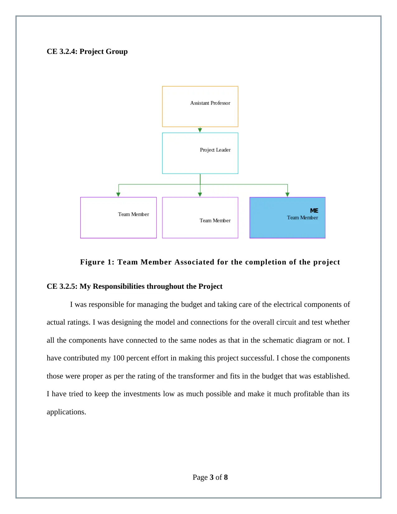
CE 3.2.4: Project Group
Figure 1: Team Member Associated for the completion of the project
CE 3.2.5: My Responsibilities throughout the Project
I was responsible for managing the budget and taking care of the electrical components of
actual ratings. I was designing the model and connections for the overall circuit and test whether
all the components have connected to the same nodes as that in the schematic diagram or not. I
have contributed my 100 percent effort in making this project successful. I chose the components
those were proper as per the rating of the transformer and fits in the budget that was established.
I have tried to keep the investments low as much possible and make it much profitable than its
applications.
Page 3 of 8
Paraphrase This Document
Need a fresh take? Get an instant paraphrase of this document with our AI Paraphraser
CE 3.3: Distinctive Activity
CE 3.3.1: Comprehending the Theory of the Project
The whole project was divided into three states that include Delta connected state, Open
State, and Star Connected State. When the current is supplied to the Star and Main contactors
remain complete and closed circuit. Across each winding, the voltage of the line-voltage has
been reduced by 1/√3 times. After motor reaches at a good rotational speed of about 90% of the
rated r.p.m, timer connects the delta contactors with the motor and disconnects the star contactor.
During the exchange of the connection from star to delta connections for some instance the
circuit become an open circuit for the motor and this state is known as open transition switching.
Line voltage and voltage applied to the windings are same in the delta connection.
Figure 1: Star and Delta Connections
CE 3.3.2: Engineering Knowledge and Skills applied in the project
The delta and star connections are preferably mechanically interlocked and electrically
interlocked as well. I have used the four states those have been resulted because of this
interlocking mechanism: OFF state. I had kept all the contactors at open star state and main and
star contactors were kept at closed whereas, delta contactors were open. I have also implemented
the mechanism that even the circuit is not closed there will be certain voltage at one end and thus
there will be no current on the other side. I had also implemented the mechanism of motor
Page 4 of 8
working as generator due to its spinning rotor. I have also implemented a protector system
through voltage fluctuation in manner to protect the induction motor from being damaged.
CE 3.3.3: Accomplishment and Task Performed
I have designed and implemented all the electrical components in manner to be portable
and compact. I have introduced the voltage regulator protective system in manner to protect the
induction motor from being damaged due to the eddy current effects or high voltage. I have tried
the basic electrical engineering ideas related to the star and delta connections for the windings of
the coil in manner to reduce the start current with a factor of by 1/√3 that equals to 0.58 of the
current or voltage supplied to the windings. This also helps in reducing the current with a factor
of one-third of the direct starting current.
CE 3.3.4: Identified Issues and Their Solutions
Issue: This starting method resulted in power quality problems as compared to that of the
autotransformer and D.O.L. for the motors whose ratings have been less than 2.2kW or 3hp. The
most emphasizing problem was the time lagging at which the motor was transforming into an
open circuit.
Solution: To eliminate power quality problems I had used the motors with high rating
and those are used for the commercial use. For eliminating the time gap issues, we had
introduced an extra power supply that will be providing voltage at one end and thus spinning
rotor mechanism of the motor will behave as a generator.
CE 3.3.5: Plan for producing creative and innovative work
This was my idea to implement three contractors in manner to operate the project with
complete efficiency of the four states those have been stated in the above paragraph. Star/delta
Page 5 of 8
⊘ This is a preview!⊘
Do you want full access?
Subscribe today to unlock all pages.

Trusted by 1+ million students worldwide
connection for the startup current is not a completely new idea but I have applied it in an
innovative way through implementing two contactors AC3 rated 58 percent of the rating of the
motor. Industrial motor world has been chosen for this project, as the application of star delta
connection for the start-up is not much efficient with the motors of low ratings.
CE 3.3.6: Collaborative work
The project was carried with a group of three members, a project leader and an assistant
professor and everyone was contributed to their individual contributions. The assistant professors
helps us and provided the guidance of which element should be taken for the project. The idea
was a group discussion and choosing contactors and adding an additional power supply was the
result of that group discussion. Contactors were used as the replacement for the brushes and we
had calculated the speed of the motor as per the frequency of the current supplied to the
induction motor. We had designed the project in a manner that the motor will be connected to the
star and at one-third of the current, it will be producing one-third of the DOL torque.
CE 3.4: Project Review
CE 3.4.1: Project Overview
This project had been designed in manner to provide low voltage start or current start to
the induction motors. Approach has been made to convert star to delta in manner to decrease the
start current for the induction motors. A set of 12V DC relays has been used in this project
including an electronic adjustable timer in manner to start the three-phase motor at AC main
supply of 50 HZ and 440V. During the execution of the project, there are chances that the three-
phase motor might be damaged if any of the phases goes missing, so this project has also the
provision of single-phase protection.
Page 6 of 8
Paraphrase This Document
Need a fresh take? Get an instant paraphrase of this document with our AI Paraphraser
CE 3.4.2: My contribution to work
I gave my contribution to the project for the system modeling and it was my
responsibility to look after the star delta starter. I had implemented the theory in the practical and
highlighted that motors at their idle condition have same property as the short-circuited
transformer at the secondary side as the bars of the rotors have been connected to form a closed
path. This leads to the eight to ten times more current drawing when the rotor starts and I had
suggested that it is necessary to minimize the voltage applied to the motor.
Page 7 of 8
1 out of 8
Related Documents
Your All-in-One AI-Powered Toolkit for Academic Success.
+13062052269
info@desklib.com
Available 24*7 on WhatsApp / Email
![[object Object]](/_next/static/media/star-bottom.7253800d.svg)
Unlock your academic potential
Copyright © 2020–2025 A2Z Services. All Rights Reserved. Developed and managed by ZUCOL.


