Introduction to Computer Networking
VerifiedAdded on 2021/08/12
|70
|20552
|120
AI Summary
Contribute Materials
Your contribution can guide someone’s learning journey. Share your
documents today.
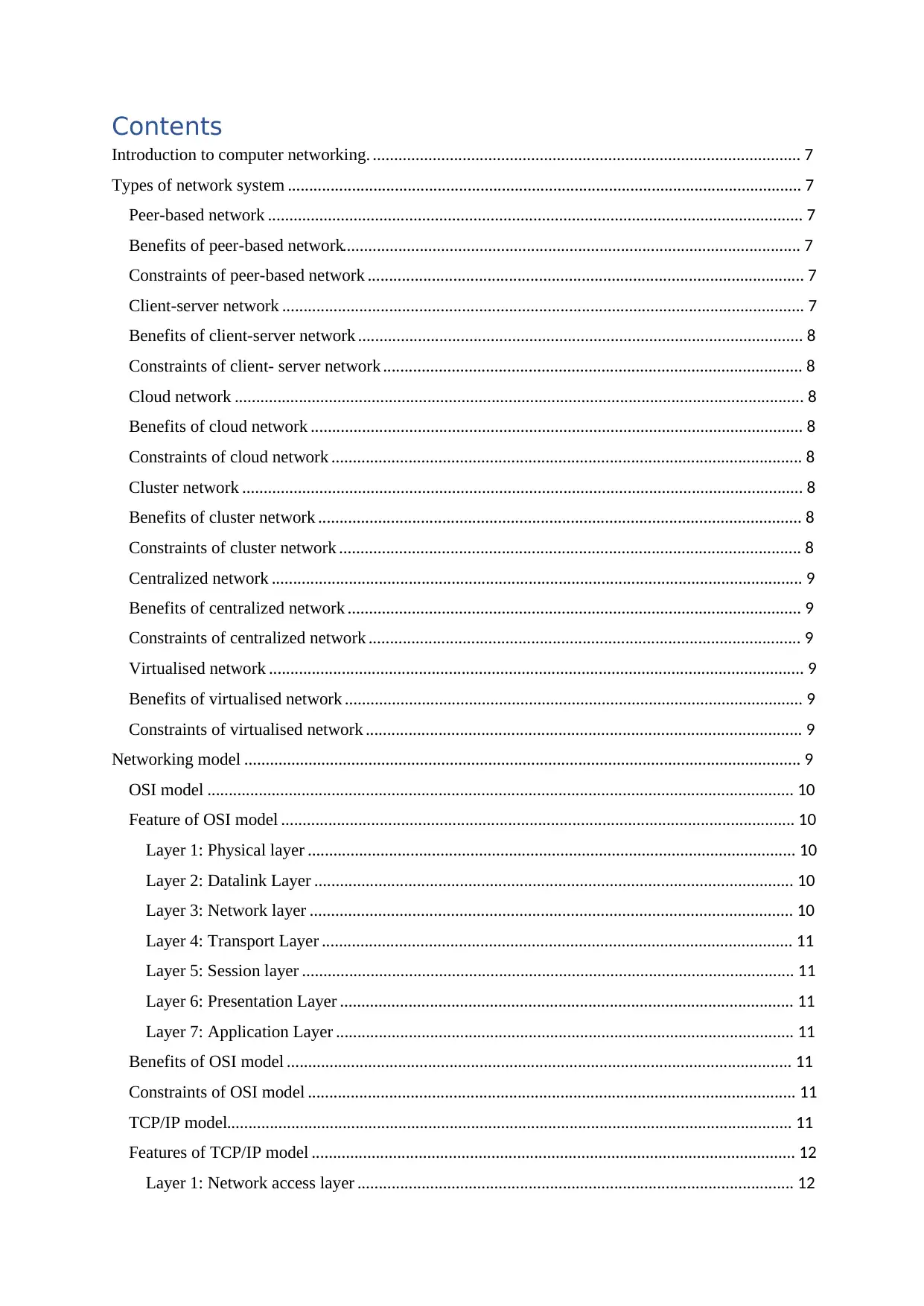
ASSIGNMENT COVER SHEET
STUDENT DETAILS
Student ID Reg No.
Family Name DEVKOTA Given NameANISH
Enrolment Year2020 Section L
Semester FIRST Email anishdevkota@ismt.edu.n
p
UNIT DETAILS
Unit Title Unit Code
Assessor Name Issued Date
Assignment Title
Assignment No1/1 Submission Date
Qualification Campus ISMT
INTERNATIONAL SCHOOL O
MANAGEMENT & TECHNOLOG
Secure Best Marks with AI Grader
Need help grading? Try our AI Grader for instant feedback on your assignments.
STUDENT ASSESSMENT SUBMISSION AND
DECLARATION
When submitting evidence for assessment, each student must sign a declaration
confirming that the work is their own.
Student Name Anish devkota Assessor Name Krishna Parajuli
Issue Date Submission Date
Programme BTECH HND leading to bsc.IT
Unit Name
Assignment Title Lotus Inc. Cosmetics
Plagiarism
Plagiarism is a particular form of cheating. Plagiarism must be avoided at all costs and
students who break the rules, however innocently, may be penalized. It is your
responsibility to ensure that you understand correct referencing practices. As a
university level student, you are expected to use appropriate references throughout and
keep carefully detailed notes of all your sources of materials for material you have used
in your work, including any material downloaded from the Internet. Please consult the
relevant unit lecturer or your course tutor if you need any further advice.
Student Declaration
I certify that the assignment submission is entirely my own work and I fully understand
the consequences of plagiarism. I understand that making a false declaration is a form
of malpractice.
Student signature: Anish Devkota Date:
Pearson Education 2018
Higher Education Qualifications
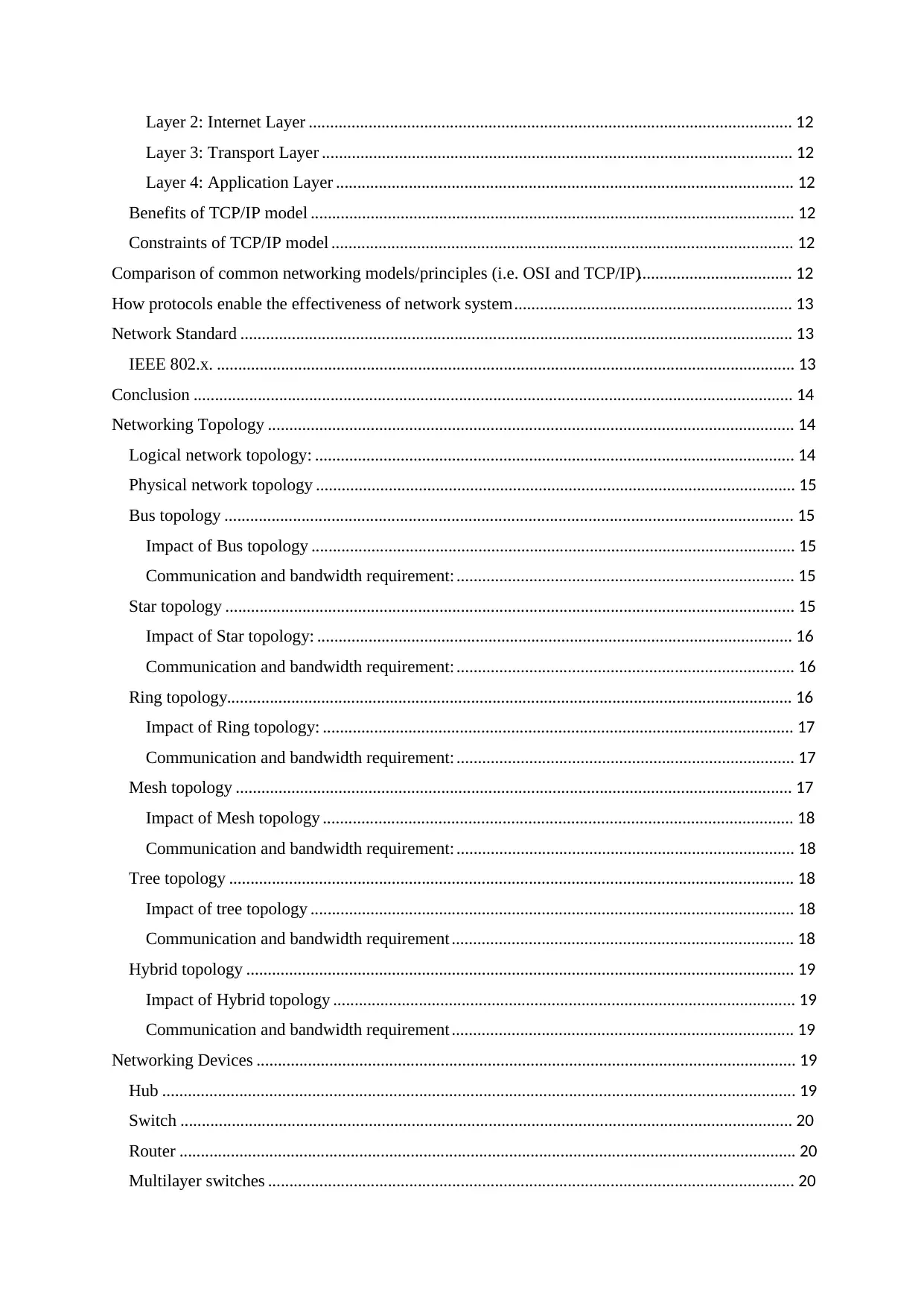
Contents
Introduction to computer networking. .................................................................................................... 7
Types of network system ........................................................................................................................ 7
Peer-based network ............................................................................................................................. 7
Benefits of peer-based network........................................................................................................... 7
Constraints of peer-based network ...................................................................................................... 7
Client-server network .......................................................................................................................... 7
Benefits of client-server network ........................................................................................................ 8
Constraints of client- server network .................................................................................................. 8
Cloud network ..................................................................................................................................... 8
Benefits of cloud network ................................................................................................................... 8
Constraints of cloud network .............................................................................................................. 8
Cluster network ................................................................................................................................... 8
Benefits of cluster network ................................................................................................................. 8
Constraints of cluster network ............................................................................................................ 8
Centralized network ............................................................................................................................ 9
Benefits of centralized network .......................................................................................................... 9
Constraints of centralized network ..................................................................................................... 9
Virtualised network ............................................................................................................................. 9
Benefits of virtualised network ........................................................................................................... 9
Constraints of virtualised network ...................................................................................................... 9
Networking model .................................................................................................................................. 9
OSI model ......................................................................................................................................... 10
Feature of OSI model ........................................................................................................................ 10
Layer 1: Physical layer .................................................................................................................. 10
Layer 2: Datalink Layer ................................................................................................................ 10
Layer 3: Network layer ................................................................................................................. 10
Layer 4: Transport Layer .............................................................................................................. 11
Layer 5: Session layer ................................................................................................................... 11
Layer 6: Presentation Layer .......................................................................................................... 11
Layer 7: Application Layer ........................................................................................................... 11
Benefits of OSI model ...................................................................................................................... 11
Constraints of OSI model .................................................................................................................. 11
TCP/IP model.................................................................................................................................... 11
Features of TCP/IP model ................................................................................................................. 12
Layer 1: Network access layer ...................................................................................................... 12
Layer 2: Internet Layer ................................................................................................................. 12
Layer 3: Transport Layer .............................................................................................................. 12
Layer 4: Application Layer ........................................................................................................... 12
Benefits of TCP/IP model ................................................................................................................. 12
Constraints of TCP/IP model ............................................................................................................ 12
Comparison of common networking models/principles (i.e. OSI and TCP/IP).................................... 12
How protocols enable the effectiveness of network system ................................................................. 13
Network Standard ................................................................................................................................. 13
IEEE 802.x. ....................................................................................................................................... 13
Conclusion ............................................................................................................................................ 14
Networking Topology ........................................................................................................................... 14
Logical network topology: ................................................................................................................ 14
Physical network topology ................................................................................................................ 15
Bus topology ..................................................................................................................................... 15
Impact of Bus topology ................................................................................................................. 15
Communication and bandwidth requirement: ............................................................................... 15
Star topology ..................................................................................................................................... 15
Impact of Star topology: ............................................................................................................... 16
Communication and bandwidth requirement: ............................................................................... 16
Ring topology.................................................................................................................................... 16
Impact of Ring topology: .............................................................................................................. 17
Communication and bandwidth requirement: ............................................................................... 17
Mesh topology .................................................................................................................................. 17
Impact of Mesh topology .............................................................................................................. 18
Communication and bandwidth requirement: ............................................................................... 18
Tree topology .................................................................................................................................... 18
Impact of tree topology ................................................................................................................. 18
Communication and bandwidth requirement ................................................................................ 18
Hybrid topology ................................................................................................................................ 19
Impact of Hybrid topology ............................................................................................................ 19
Communication and bandwidth requirement ................................................................................ 19
Networking Devices .............................................................................................................................. 19
Hub .................................................................................................................................................... 19
Switch ............................................................................................................................................... 20
Router ................................................................................................................................................ 20
Multilayer switches ........................................................................................................................... 20
Secure Best Marks with AI Grader
Need help grading? Try our AI Grader for instant feedback on your assignments.
Firewall ............................................................................................................................................. 20
HIDS ................................................................................................................................................. 20
Repeaters ........................................................................................................................................... 20
Bridges .............................................................................................................................................. 20
Wireless devices................................................................................................................................ 21
Access point ...................................................................................................................................... 21
Content filter ..................................................................................................................................... 21
Load balancer .................................................................................................................................... 21
Modem .............................................................................................................................................. 21
Packet shaper .................................................................................................................................... 21
VPN concentrator .............................................................................................................................. 21
Types of server ...................................................................................................................................... 21
Web server ........................................................................................................................................ 21
File server.......................................................................................................................................... 22
Database server ................................................................................................................................. 22
Combination ...................................................................................................................................... 22
Virtualisation..................................................................................................................................... 22
Terminal services server ................................................................................................................... 22
Conclusion ............................................................................................................................................ 22
Interdependence of workstation hardware and relevant networking software ...................................... 22
Selection of the best server ................................................................................................................... 23
Therefore, we have decided to select the IBM server. Then we compare the server models and make
up our decision of which server to use. After some research and comparison, server was selected
according to the budget, performance and reviews. Here, we described and compared three different
servers with their specifications or features. Below are some servers that we researched and find more
compatible and suitable for our organization (Global IT solutions). .................................................... 23
Selection of the best network topology ................................................................................................. 24
Conclusion ............................................................................................................................................ 25
Design of network ................................................................................................................................. 25
Server technology used in our network ................................................................................................. 25
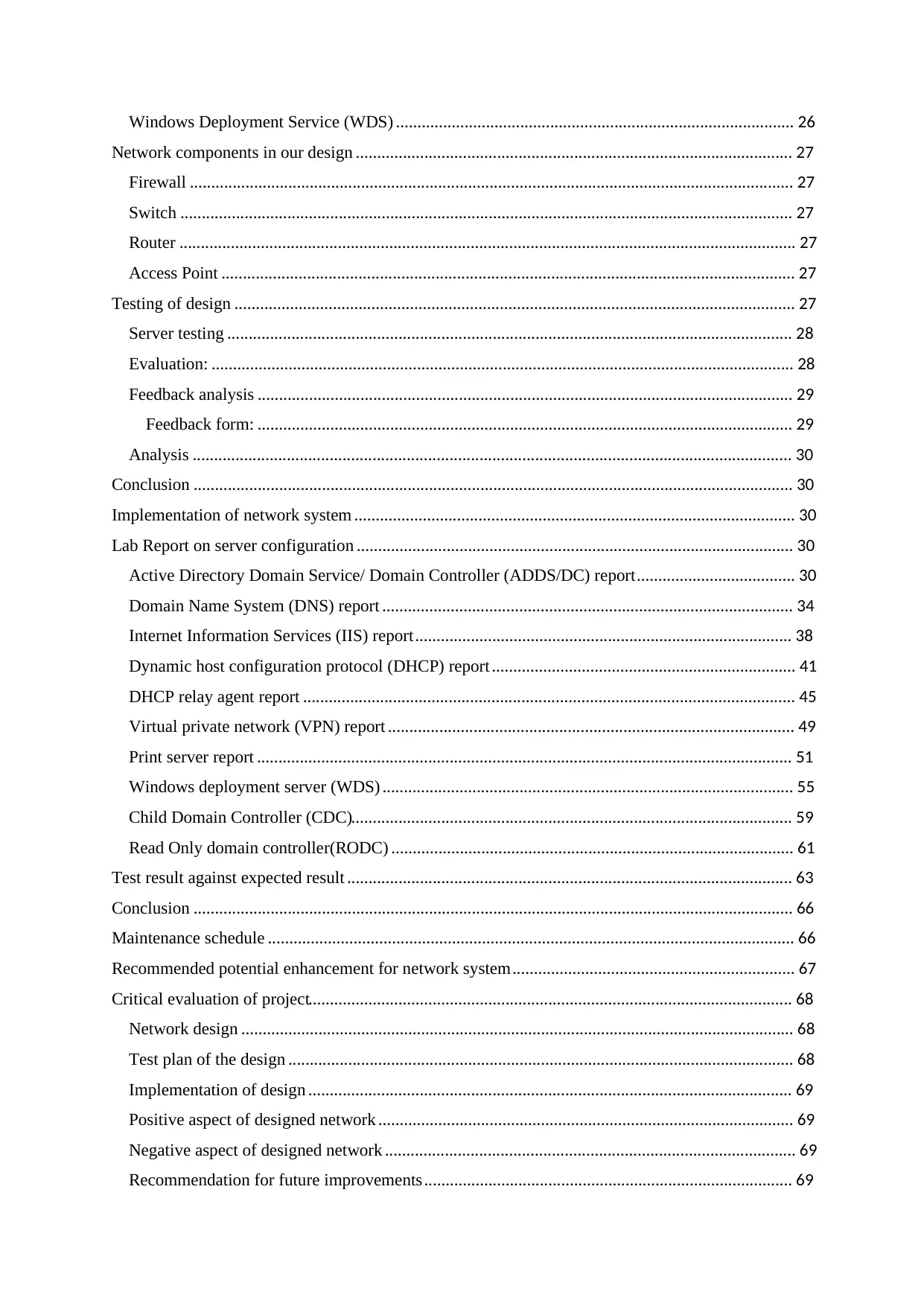
Domain controller (DC) .................................................................................................................... 26
Domain name service (DNS) ............................................................................................................ 26
Dynamic host configuration protocol (DHCP) ................................................................................. 26
Read-only domain controller (RODC) .............................................................................................. 26
Child domain controller (CDC) ........................................................................................................ 26
Print server (PS) ................................................................................................................................ 26
DHCP relay agent ............................................................................................................................. 26
Windows Deployment Service (WDS) ............................................................................................. 26
Network components in our design ...................................................................................................... 27
Firewall ............................................................................................................................................. 27
Switch ............................................................................................................................................... 27
Router ................................................................................................................................................ 27
Access Point ...................................................................................................................................... 27
Testing of design ................................................................................................................................... 27
Server testing .................................................................................................................................... 28
Evaluation: ........................................................................................................................................ 28
Feedback analysis ............................................................................................................................. 29
Feedback form: ............................................................................................................................. 29
Analysis ............................................................................................................................................ 30
Conclusion ............................................................................................................................................ 30
Implementation of network system ....................................................................................................... 30
Lab Report on server configuration ...................................................................................................... 30
Active Directory Domain Service/ Domain Controller (ADDS/DC) report ..................................... 30
Domain Name System (DNS) report ................................................................................................ 34
Internet Information Services (IIS) report ........................................................................................ 38
Dynamic host configuration protocol (DHCP) report ....................................................................... 41
DHCP relay agent report ................................................................................................................... 45
Virtual private network (VPN) report ............................................................................................... 49
Print server report ............................................................................................................................. 51
Windows deployment server (WDS) ................................................................................................ 55
Child Domain Controller (CDC)....................................................................................................... 59
Read Only domain controller(RODC) .............................................................................................. 61
Test result against expected result ........................................................................................................ 63
Conclusion ............................................................................................................................................ 66
Maintenance schedule ........................................................................................................................... 66
Recommended potential enhancement for network system .................................................................. 67
Critical evaluation of project................................................................................................................. 68
Network design ................................................................................................................................. 68
Test plan of the design ...................................................................................................................... 68
Implementation of design ................................................................................................................. 69
Positive aspect of designed network ................................................................................................. 69
Negative aspect of designed network ................................................................................................ 69
Recommendation for future improvements ...................................................................................... 69
Conclusion ............................................................................................................................................ 70
Introduction to computer networking.
Interconnecting two or more than two computers in a single network connected wirelessly or
with the help of wire is determined as computer networking. The main purpose of computer
networking is communication, sharing files and resources. Simply computer networking is
known to be the collection of devices or computers connected together with different
communication devices and transmission media. Firstly, advantage of computer networking
is sharing of file and data would be easier. When computers are interconnected with each
other there can be sharing of hardware devices like printers or scanners due to which work
can be done continently and in a cheaper way. Each and every computer can access data and
file from server by following server protocols or rules. (BegineersBook, n.d.)
Mentioning about the disadvantage, main server failure leads to failure in approaching the
data or files. Hacking, viruses or malware attacks could occur and data might not be safe.
Skilled man power is required for operating the network. Networking of computers is costly
for large scale companies (i.e., buying of networking devices, hiring an it expert, network
cables etc.).
Therefore, being aware of the out coming negative consequences we can implement the
convenient use of computer networking in proper ways and make our life easier and faster.
Types of network system
Peer-based network
It is a network system specially designed or suitable for small to medium local area network.
This system allows user to share resource and files from one node or computer to other one.
In this type of system, every computer is connected with each other without central server.
Each and every connected computer are equally powerful in this network.
Benefits of peer-based network
In this network, due to small scale there will be ease in setup (i.e. configuring and connecting
computers or nodes). There will be less requirement of hardware and no server needs to be
established. This type of system would be cheaper. each and every user can control own
resources. In this network data files can be shared directly from sender to destination.
Constraints of peer-based network
This type of network doesn't compulsorily use server so there won't be centralized network
and central location for storage. There would be lack of security in this network. This type of
server is not favourable for large scale organization. This network is not suitable for large
scale organization which shows the lack of centralized network.
Client-server network
In this network system, all the computers are connected to the central device called server.
Client server system is a system that allows users to access the resources through a server.
Data or the files are stored centrally to the server and transferred to the destination. This
system is very helpful and suitable for large scale organization which requires a centralized
Paraphrase This Document
Need a fresh take? Get an instant paraphrase of this document with our AI Paraphraser
network, security etc. Here, server is the main component which controls, manage and
provides services to the entire network.
Benefits of client-server network
Client server uses server due to which there would be more security, data would be stored
and backed up centrally and there will be less chance of data or information loss. This type of
system is properly managed by the server. Different machines can remotely access server
from different locations.
Constraints of client- server network
Talking about costing, this system is costlier. This server requires a regular maintenance.
Highly skilled man power is required for maintaining this server. A server failure will affect
the entire network system.
Cloud network
Cloud network system means storing or retrieving resources or data in an internet without
using a storage system of computer. Therefore, cloud is known as a network or internet.
google drive, drop box, one drive, etc. are some of the examples of cloud system. We can
access the saved data whenever we can and use the free space provided to us. Cloud network
can be hosted on private, public and hybrid cloud.
Benefits of cloud network
This type of network reduces the expenses of any organization in various ways likely by
reducing the additional requirements of hardware and software. Data can be accessed easily
from the cloud whenever we want. This system helps in increasing the storage capacity of a
node.
Constraints of cloud network
As, we are given the space to save our data but failure of internet would let us in unable to
access the data stored in cloud. Overload in server may occur because of various clients
which may lead us to non-ignored cases in business or many works. Mainly, there is a risk of
hackers or data thief due to which our data can be stooled or approached by unwanted
persons.
Cluster network
Cluster networking refers to the grouping of different computers and servers in a single
network and making it work as a single machine. All the computers in cluster are made to do
same task. These tasks are managed and controlled by software and connected through
dedicated network.
Benefits of cluster network
Certain task can be done in a very fast way because of all computers working as a single. It
would be very helpful for data recovery because same task is done in others nodes too. One
node or computers fails then it won't fail the work. In cluster networking we can add many
computers easily (i.e., ease expandability).
Constraints of cluster network
For clustering more servers and hardware are required in establishing this network due to
which handling or maintaining of this would be difficult. Comparing to non-clustered server
design good hardware and design are required which can be costly.
Centralized network
centralized network refers to the network connected to a central server. This network is
sharing a same concept of client-based network. In this network, server would store both
communications and data or information. Central server is a main factor for providing and
processing resources to the client nodes. One main example of centralised networking can be
instant public messaging.
Benefits of centralized network
Files or data in this network are stored and backed up centrally which makes users to absorb
the required data easily and saves the time. This system does not require centralized database.
Costing will be less because it can be managed using fewer members or network experts.
There will be easier in implementing common policies and practices. Management,
monitoring and troubleshooting of network is found to be lot easier and centrally.
Constraints of centralized network
Although having files in a centre server, clients have to be depended upon the server. Failure
of the server hampers the entire network system. It is found to be less secured then
decentralized server so, there will be more chances for hacking or losing data. This network
is also not suitable for small scale organization.
Virtualised network
Virtualisation network is determined as network system that simplify and monitor the
communication of data between two or more virtual machines (that might be servers or
computers). In this network, data transfer rate will be divided in order to separate server or
network devices. Using virtualised network one can check the security, bandwidth and
reliability of the network.
Benefits of virtualised network
Mainly, virtualised network is cheaper because there won't be any need of buying different
servers and computers. Even after being attacked, data would be recovered and backed up
easily. All the machines share the same resources of host yet each works independently and
this helps in faster resource deploying.
Constraints of virtualised network
Firstly, this network consumes more time. This network requires several links to work
together for performing task. There is also seemed to be security risk in this network. Every
application or server may not work within an environment of virtualization. (Essay[ZZ..],
2021), (Bourgeois, n.d.)
Networking model
Every process for sending and receiving data are separated in a layer for simplifying network.
Networking models describes about the process as a layer and how data is transferred and
displayed. There are two types of networking models and mentioned by OSI model and
TCP/IP model.
OSI model
Figure:1
Open System Interconnection (OSI) model is a certain type of networking model which is an
open standard system for communications. Being able to fit anywhere makes it open source
of model.
Feature of OSI model
Being an open source, this model can describe the flow of data easily. Having separate layers,
there would be more ease in troubleshooting problems. In this model, work of hardware and
software can be seen. Therefore, OSI model is divided into seven layers and their functions
are described below:
Layer 1: Physical layer
Being in the lowest layer this is the first phase where raw data are transmitted over a
network. This layer also can be known as hardware layer that poses actual physical
connection between devices. This layer converts a user data into computer-based language
and transfer it to datalink layer. Hub,repeater,modem are some major examples of physical
layer.
Layer 2: Datalink Layer
This layer makes sure that data transfer is error free. This layer also works at delivering
message from one node to another. This layer transmits data or packet to the host by the use
of MAC address. Example of this layer are switch and bridge.
Layer 3: Network layer
This layer is also a hardware layer that works for transmission of data through
different channels from one computer to another. This layer helps in searching and deciding
the easiest and fastest path for transferring data.
Secure Best Marks with AI Grader
Need help grading? Try our AI Grader for instant feedback on your assignments.
Layer 4: Transport Layer
Being called as heart of OSI model, this layer is mainly responsible for end-to-end message
delivery. This layer functions in breaking a data into small units transferring correct data and
retransmitting whenever error is found. This layer also takes data from both session layer and
network layer.
Layer 5: Session layer
This layer is a layer which helps in establishing connection between two of the unique
applications. This layer helps in authentication and ensures the security.
Layer 6: Presentation Layer
This layer contains the special function like data translation, data encryption and decryption
and data compression. This layer translates the data into readable and usable form. Here, data
is extracted and manipulated.
Layer 7: Application Layer
In this layer, data shown to the computers are implemented by network applications. This is
the final layer that displays the received information. This layer transfers and distributes the
results to users.
Benefits of OSI model
This model has a main advantage of supporting connection less services and connection-
oriented services. Protocol can be changed according to the technology and protocols are well
hidden in this model. Going layer wise, it makes this networking model more managed and
systematic.
Constraints of OSI model
While adjusting a protocol more time will be consumed and importantly, this model was
invented first then protocols due to which this model is mainly used as reference model.
Reference: (Webopedia, 2021)
TCP/IP model
Figure:2
Transmission Control Protocol/ Internet Protocol (TCP/IP) is reference model designed to be
survived in every severe conditions or disasters by the defence department of USA. This
model helps us in identifying how computer is connected to network and data is transmitted
between them.
Features of TCP/IP model
Basically, this model is divided into four layers. Known as network access layer, internet
layer, transport layer and application layer as described below:
Layer 1: Network access layer
This layer describes about management and controls of how the data is physically sent
through network and also checks hardware devices and medias for making network. This
layer working mechanism can be called as combination of datalink and physical layer of OSI
model.
Layer 2: Internet Layer
This layer does the main job of finding the path in network and transferring IP packets to the
expected destination. This layer functions as the network layer of OSi model. IP,
IPMC, ARP, RARP are some examples of protocols in this layer.
Layer 3: Transport Layer
Likely as transport layer of OSI model this layer also functions mainly in maintaining end-to-
end communication in entire network. This layer supports the communication between
diverse devices and the network. This layer is also a responsible layer for providing error free
data. Some protocol examples are TCP, UDP, RDP.
Layer 4: Application Layer
The application layer describes TCP/IP protocols and how the data is transferred by checking
how the host interfaced with transport layer. Some of the examples of protocols are HTTP,
DNS, SMTP etc.
Benefits of TCP/IP model
The main benefit of using TCP/IP is, all the connected nodes will be assigned different IPs
and this would make every device identified or known. Any nodes can use protocols from
this model because of having, no strict boundaries. This model is more affective in practical
type of networking.
Constraints of TCP/IP model
The problem in TCP/Ip is mentioned as not providing assurance delivery of packets or files.
Because of providing connectionless services, this model can be only favourable for wide
area network.
Comparison of common networking models/principles (i.e. OSI and TCP/IP)
OSI model TCP/IP model
This model follows the protocol of
communication between end user
and network.
This model follows the standard
protocol which helps in connection
of host in a network.
The packets flow in this model is
guaranteed by transport layer.
Although being reliable, delivery of
data packets is not guaranteed by
transport layer of this model.
OSI model mainly follows the
vertical approach of packets.
TCP/IP model follows the horizontal
approach of packets.
Transport layer of this model is
connection based.
Transport layer of this model might
be connection based or
connectionless.
Network layer of this model can
give connection based as well as
connectionless services.
Network layer of this model gives
connectionless services.
This model is generally used as
guidance tool.
This model is used as
implementation.
This model was described after
arrival of internet.
This model was described before the
arrival of internet.
Reference: (Guru99, n.d.).
How protocols enable the effectiveness of network system
There are different types of medium that affects the network system of a specific network.
Protocol is one of the main factors for enabling the effective network system. Simply,
protocol can be defined as sets of rules or regulations to be followed by a computer in order
to communicate or share resources in a network. A protocol in network system helps in
identifying the server and clients using IPs, transfer files between server and clients, send
respond from server to the requested clients, etc and improves the performance of a system
by its functionality. Protocols also helps in encrypting and decrypting of data which makes
the system secured. Basically, there are many protocols that functions different from each
other. Some of the protocols are; HTTP (Hypertext transfer protocol), FTP (File transfer
protocol), TCP/IP (Transmission control protocol/Internet protocol), SMTP (Simple mail
transfer protocol), POP (Post office protocol) etc.
Network Standard
Network standard is a standard that defines the physical and technical specifications about the
network being designed for example; physical layout, cabling and maintaining access
communication between network media. This standard describes about the protocols of
communication for networked devices. IEEE, ISO, ANSI etc are some of the organizations
that coordinates this standard.
IEEE 802.x.
This is one of the family of IEEE (Institute of Electrical and Electronics Engineers) dealing
with local area network and metropolitan area network. This standard can be compared to the
datalink layer and physical layer of OSI model. IEEE consists of different work group and
some groups are mentioned as below:
Paraphrase This Document
Need a fresh take? Get an instant paraphrase of this document with our AI Paraphraser
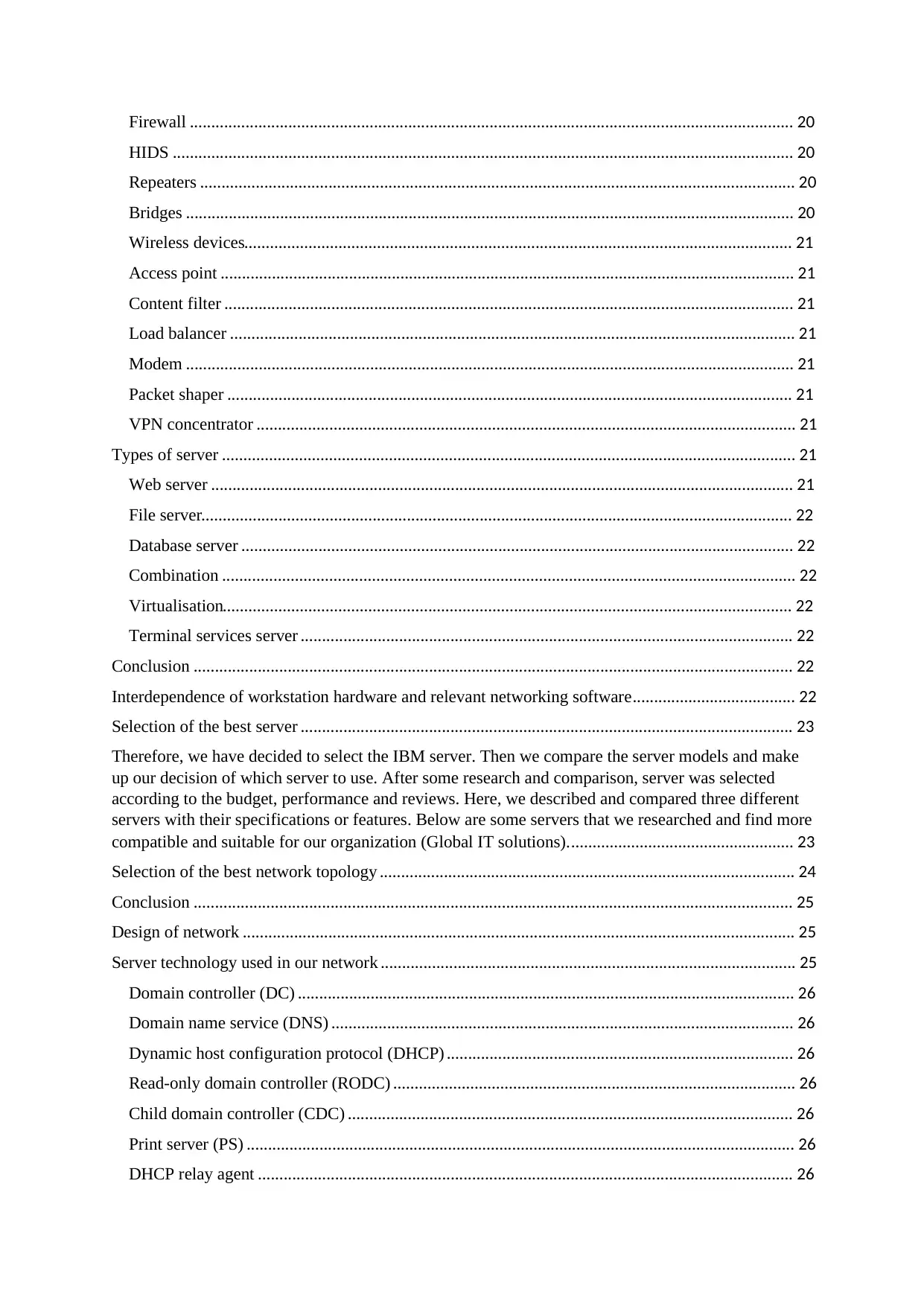
Figure: 3
Reference: (Yong, n.d.)
Conclusion
Basically, benefits and constraints of different network models and standards are described
above including their layers and features. As per research, we can get that TCP/IP model is
practical and the most used common networking model.
Networking Topology
Network topology is a manner in which two or more computers are arranged to relate with
each other over internet. This is also explained simply as the arrangement of computers
connected in a network.
The types of network topologies are:
Logical network topology:
The logical topology, in contrast, is the way that the signals act on the network media, or the
way that the data passes through the network from one device to the next without regard to
the physical interconnection of the devices.
Example: Ethernet, Token Ring
Ethernet
Ethernet refers to the wired protocol where one node is connected to another in
network via wire. Also, ethernet protocol can be called as logical bus topology.
Token ring
It is a communication protocol that circulates along the ring of the station. Also,
Token ring can be called as logical ring topology.
Physical network topology
The way that the workstations are connected to the network through the actual cables that
transmit data — the physical structure of the network — is called the physical topology.
Example: Star,Bus,Ring,Mesh,Tree,Hybrid.
Bus topology
Bus topology is a type of network topology where each computer is connected in a single
wire. The wire is the main medium which transfer the data from one computer to another in a
single direction. Wire is also called as backbone for this topology.
Figure:4
Impact of Bus topology
This type of topology is most suitable for small area network like LAN. Any computer failure
does not affect the entire network system and there will be ease in connecting new computer
in this topology. Mainly, problem in a main cable will affect the entire network and network
will be failed. If many computers are connected, then it will hamper the network speed. This
topology won't be suitable for large scale network.
Communication and bandwidth requirement:
In this topology, sender will send the data and receiver will receive it through a wire in a
sequence. Different computers must be connected in a single wire or linear cable without
using central medium or device and using terminator at each end.
Star topology
Star topology is a type of topology where hub is used as central connection point and
data is transferred from one node to another using it. Therefore, we can replace hub by switch
or routers as well.
Figure:5
Impact of Star topology:
The main benefit of star topology is, a certain failure in a single node does not affect the
entire network system. Whole network is managed by central devices which makes it
systematic. There will be easy in installing or adding new computer to the network in this
topology. Failure in a central device will affect the entire network which is the main
disadvantage of star topology. And simply due to central devices like hub, switch etc costing
will be high.
Communication and bandwidth requirement:
For connection of certain computer in star topology, there must be a hub or central devices
which transfer data from one node to another. Also, computer must be connected to the
central device for being in this topology.
Ring topology
A ring topology in which all the computers are connected in a closed loop. Data in this
topology circulates in real ring-shaped network without any endpoint or start point. Mainly,
ring topology must not compulsorily be in ring shaped. There are two types of ring topology:
1.Unidirectional:
This type of ring topology handles either clockwise or anti-clockwise at a time.
2.Bidirectional:
This type of ring topology handles both clockwise and counter clockwise direction.
Secure Best Marks with AI Grader
Need help grading? Try our AI Grader for instant feedback on your assignments.
Figure:6
Impact of Ring topology:
As not being starting and ending point, data will flow faster than bus topology. Each and
every computer connected are equally powerful and can regenerate data. Packet from one
node travels to another node until they reach their final destination. Signals in this topology
moves in single direction. Although, single node failure in a connection will hampers the
entire network in this topology. There is likely more load and less good performance in this
type of topology.
Communication and bandwidth requirement:
In this topology one will be sending a data in a network and data will be passed to one and
another each by each until data is accessed by destination. For this topology there must be
small area network or simply connected in peer-based network. Sender must go through all
the process to transfer data to destination.
Mesh topology
Mesh topology is a type of topology where each and every computer are interconnected with
one another directly. It does not have any sorts of physical design or shape. This type of
topology is mainly helpful for wireless type of network.
Figure:7
Impact of Mesh topology
As, all the nodes are connected to each other due to this data can be transferred from one to
another directly. Failure in one system does not affect the entire network in this topology.
One computer can transfer data to multiple nodes at once. Because of nodes connection to
each other, there would be expensive expenses. Adding or removing computer from this
topology will be difficult. Mesh topology is a suitable topology for wide area network.
Communication and bandwidth requirement:
For the communication in this topology, mainly one node must have a direct connection with
another node in a network system. One node should be connected with another via wire.
Tree topology
Tree topology is a type of topology where all the devices are connected like a branch of tree
in a single network system. As, we can see the perfect figure of tree topology below:
Figure:8
Impact of tree topology
Here many computers are connected to the branches of the main computer. Using this
topology, one node can be easily connected or disconnected in a network. Error detection in
this topology is easily done and this topology is easily managed and maintained. Due to
heavy cabling, this topology connection is found to be costlier. When the main device or
node is affected then all the system is affected. High number of connections of branch nodes
will make the system maintenance difficult.
Communication and bandwidth requirement
For being connected in a tree topology, there must be a main computer and nodes connected
to the branches of the main computer. Computer can be added into the sub branches and be
able to share resources.
Hybrid topology
Hybrid topology is a type of topology formed by two or more types of topologies. We can
assume an organization using two topologies and when both are connected hybrid topology is
formed. Image of hybrid topology is given below:
Figure:9
Impact of Hybrid topology
This topology gives an advantage of easy trouble shooting and fixing the problem. This type
of topology is flexible to use due to which there will be no difficulty in increasing nodes or
size of network. Although being flexible, this topology is difficult in designing. Many
topologies are connected to one due to this cost will be high for example; in cabling.
Communication and bandwidth requirement
Basically, for a node to be connected in this topology one node should be a member of a
certain topology connected in hybrid. If connected to the single topology of hybrid topology,
one node will be able to share or get access to information or data files in the hybrid
topology.
All reference: (studytonight, 2018)
Networking Devices
Networking devices are the communicating devices which are used for connecting different
computers or electronic gadgets together for data sharing and extracting. This is a medium of
sending and receiving data on the network.
There are different types of networking devices and some of them are described below:
Hub
Hub is a type of networking device that connects all the devices together in a single network.
Hub contains multiple port where nodes are connected and sharing files or resources is done.
Talking about the working mechanism, a sender sends the data to hub and hub passes the data
to the receiver. Although hub sends the data to receiver but it has a disadvantage of not
Paraphrase This Document
Need a fresh take? Get an instant paraphrase of this document with our AI Paraphraser
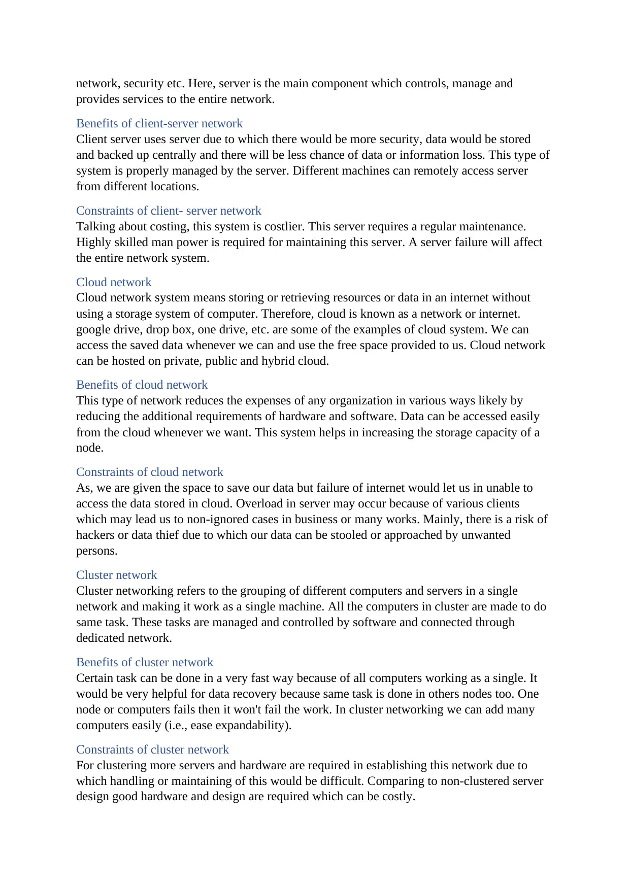
filtering the sent data and occurring data collision because of data sending data in every ports.
Hub also accepts the internet connection via its port.
Switch
Switch is a networking device which is very similar to hub but a little different due to its
work. Switch can also be called as a multiport device like hub. When a sender in this media
sends data then it will move to the switch and switch transfers the data in exact destination of
network using physical address (i.e., MAC). MAC address of connected nodes will be stored
in switch and data is sent wherever required (not in every port like hub). This is the main
function that differs switch and hub. Switch works for the datalink layer of OSI model.
Router
Router is a type of networking device that sends or provides data from one network to
another via IP address. This device mainly functions in connecting different network
segments. When data is sent to the router, there will be the inspection of data’s IP address and
finds the path where it is requested. Mainly, due to the firewall built-in routers are more
secured. Also, bandwidth of router is found to be high.
Multilayer switches
A networking device having both functionalities of switching and routing is Multilayer
switch. Having both functions, this device can perform task incredibly fast. Multilayer
switches routes packet on ASCI hardware. Being fast with best performance, this device is
capable of operating high layers of OSI reference model.
Firewall
Firewall is a networking media either in a form of software or hardware that protects or
controls the data for unwanted attacks or risks. The main purpose of firewall is to make a
network secured without any information being leaked or stole. Also, firewall helps in
protecting a network or nodes from different malwares or viruses.
HIDS
Host-based Intrusion Detection System (HID) is a type of networking device that monitors or
manage a node and network packets in its network. This device helps in analysing the
unusual log in or activities in a certain network. Simply, this device is also main functioning
in a security of a network.
Repeaters
Repeater is a type of electric device that receives the data signals from the sender and
increase the rate of signals and send to the receiver. This device mainly functions in physical
layer. This device receives the signals and amplify the signals and rebroadcast it in a clear
way. Some examples of repeater are telephone repeater, radio repeater etc.
Bridges
Bridge is a networking device that helps to connect two or more host as well as network
segments and develops connections together in a network. This device is mainly used for
dividing the larger network into a small part and make the network simplified. This device is
very helpful for big scale organizations. Also, bridges use hardware MAC addresses for
sharing packets.
Wireless devices
One of the used networking devices in today's modern world is wireless devices. This type of
device sends or receive the data by broadcasting wave signals like radio wave or
electromagnetic wave in the air. As a example we can see computers being connected to the
internet without wired medium.
Access point
Access point is a networking medium where both wired and wireless connections are
involved. This device connected to the wired networking devices and gives a wireless signal
(Wi-Fi) to the needed area. This type of medium can be more useful in large organizations.
Content filter
Evaluating by its name, it actually functions the same. This is a set of programs that checks
the content of data whether appropriate or not. This medium also protect the network system
and increase the security. Many network users use this to be preventive from unwanted apps
or sites
Load balancer
This is a type networking device that helps in maintaining the heavy load in a server. This
device maintains the load by dividing works to the different available server due to this there
will be balance in network system. Network traffic over various servers can be processed
very fast using this medium.
Modem
Modem is a networking device that converts digitals signals to analogue signals for making
the signals travel by telephone lines. Simply modulation and demodulation of signals is the
main function of modem. Modem is used for sending and receiving the digital information
among nodes.
Packet shaper
This is the process of transferring data traffics through private or public type of network.
Packet shaper helps in identifying infected node as well as unusual traffic and protects the
performance of networks and key application.
VPN concentrator
VPN concentrator is a networking device specially designed for creating and managing VPN
connection between different nodes. This device also helps to create VPN connection and the
delivery of resources between nodes in a network. Also, VPN concentrator authenticate users
and guarantees the end-to-end delivery of data.
Types of server
Server is known as a main computer in a network and it provides information or data
information/files to the users or clients. Server helps in managing the resources in a network
system. There are various type of server and some of them are mentioned below:
Web server
Web server is an application server which helps in hosting a program and requested data to
user over internet or intranet. This server stores the data or resources and user can get access
to it by requesting into the browser. Simply, user request a data to the browser then, browser
gets and reads the data from the web server and finally data is displayed to the requesting
user.
File server
Basically, file server is a type of server that stores and manages the files in a network. File
server also handles request for files and helps in distributing the requested data to the user in
a network.
Database server
All the data in a certain organization or company is stored in a database. As, database server
helps in storing the database of a certain network and provide to the user whenever required.
Many clients might request the database at a time which makes in slow responding scene and
using this server will also help in fast replying or processing of request. Also, this server back
up the database and helps in backup or recovery of lost data.
Combination
Combination server by name has a meaning of mix up of different server. Combination server
is defined as a server formed by combining of different types of server together. This type of
server can do many requested tasks alone (like it can do both work of webserver, fileserver,
database server etc).
Virtualisation
Virtualisation of server can be defined as making a different server inside one main server.
And this made server is virtualised server. Although, virtual servers also have feature like a
main server and share the storage or processor with main server. Using virtualised server,
task or requests will be divided into servers and getting result will be easier with a less load.
Terminal services server
Terminal services server is a type of server that authenticates the login of users and checks
the accessibility of the user. This server also helps in making the resources or different
services remotely in a network.
Conclusion
The working principles or functions of different servers are mentioned above. And evaluating
this description we will be able to identify the perfect server needed for our networking area.
Interdependence of workstation hardware and relevant networking software
In a network system, software and hardware are the main components required for
networking. Both the hardware and software are very interrelated with each other like the two
parts of coins (as per sayings). Absence in a software or hardware in a system won't let in
performing any task in the network. In absence of one other stop working. For a software to
be installed and stored, there must be a hardware component. As example we know, hardware
like ram, storage, drive is required for successfully installing a software. And relevant
software controls the hardware and make it in use. For example; a software uses processor or
ram or storage of a hardware to run its process. Therefore, for a successful operation
hardware and software works together. For a networking in a system, a software with the
perfect networking functionality of must be installed and in that basis, hardware works for the
dedicated software.
Secure Best Marks with AI Grader
Need help grading? Try our AI Grader for instant feedback on your assignments.
Therefore, we also must select the relevant software for successfully operating the network
system for performing the reliable and potential task.
Hardware specifications of our good node to conduct modern network system:
Manufacturer = Acer
Model = Aspire 515-54g
Processor = intel(r) core(tm) i7 10th generation CPU@ 1.80GHz 2.30GHz
RAM = 8gb
System type = 64bits
Hard dive = 1TB + 256GB SSD
Operating system = Windows 10
Graphics = MX250 NVidia
According the given details of the hardware specifications of my node, we have chosen
VMware workstation pro-16 as a software for creating different virtual machines and
configuring different operating system according the suitable case. Using that software will
be more convenient and more reliable. Also, we have selected the operating system as 2012
r2 server to the centralized server and windows7 professional for the clients.
Selection of the best server
Therefore, for the successful networking we need to determine the appropriate server for our
organization. Server with the best budgeted price and functionality must be selected for our
organization. Also, the working limits and reliability of a server must be concerned for our
organization.
Therefore, we have decided to select the IBM server. Then we compare the server models
and make up our decision of which server to use. After some research and comparison, server
was selected according to the budget, performance and reviews. Here, we described and
compared three different servers with their specifications or features. Below are some servers
that we researched and find more compatible and suitable for our organization (Global IT
solutions).
Brand IBM IBM IBM
Model IBMx3250M4
(2583IEA) Rack
Server
IBM system
X3400M3 Tower
Server
IBM system x3550
M5 1U Rack Server
Processor Intel Xeon E3
1200v
Intel Xeon 5500
series processor,
Intel Xeon 5600
series processors
Intel Xeon E5-
2600V4
Ram 32GB 128GB 768GB
Hard disk storage 8TB 24TB 40TB
Number of
processors
1 2 2
Server type 1U Rack 5U Tower 1U Rack
Price (in pound
sterling)
614.58 1,081.66 3,539.97
Therefore, we are conducting a centralized network system for our organization. For building
a centralized network we need the powerful server with high processing speed and storage.
After having the data of different compared servers, we find IBM system X3400M3 Tower
Server as best compatible one. IBM system x3550 M5 1U Rack Server was also would have
been the best one but cost is one of the limiting factors for our organization. As per budget
and the processing capacity we choose IBM system X3400M3 Tower Server. This server hols
two latest processor in it with a processing memory of 128GB which is enough for our
organization to handle the network and services with a better performance. This server also
gives a advantage of huge storage of 24TB and this also ease our organization for saving the
data or sensible files. We have centralized network so server must be available for 24/7 hours
and must provide the facilities to the client so choosing this server will surely be the wise
decision for us. Since our organization made a conclusion of selecting this server because of
meeting the working requirements including the best budget and huge storage.
Selection of the best network topology
Selecting a best network topology is the best way for successful networking in an
organization. Hereby, for a reliable and easy networking we have to evaluate the use of
different topology and follow the favourable one.
Since above there we have discussed a detail of different protocols with their respective
impacts and constraints. Studying the different protocols and by comparing them we are
choosing the effective network topology to be followed by our Global IT solution’s network
system. After studying we came to a result of choosing star topology for our network system
or design. For our organization we need a centralized network with a powerful server so we
conclude our network to follow the rule of star topology. Above we have already selected the
suitable and reliable server for our office network which can perform the certain task that we
required for us with a best performance. Our organization must also save a large amount of
data of different clients or organizations, so following star topology will help us by storing
the sensational data securely into the server.
Star topology uses the central server due to which our network system will be protected by
firewall, malware or unnatural attacks and maintains the security. Also, we decided to follow
star topology because this helps in the network system to easily connect or disconnect nodes.
Mainly advantage factor for using star topology is, we can provide our services to the clients
for every hour of days and store and share resources by the help of central server. Star
topology also functions in giving the high data transfer rate in comparison to other topologies
that make our organization’s performance better and faster. When a connected node occurs
any failure then the entire network is not affected due to which following this topology is
very suitable for our every time service provider organization. Also due to this reason star
topology is more famous and used by different organizations. Backup and recovery of files is
easier using star topology which will be very helpful for our organization in any case of data
lost or delete (because it uses central devices where data can be collected and restored easily).
Being widely used, there will be easy for our organization to maintain or service the network.
There will be less mistakes because we use the central server that share the information or
resources to the needed nodes.
Therefore, being more effective and efficient we conclude to select the star topology. Using
star topology helps our organization to be more systematic due to the central server. The main
objective for our organization is very well managed by this network topology after studying
the objectives of our company. Hence, our team came to a conclusion of using the star
topology for our organization network.
Conclusion
Thus, we compared different servers and topologies for building our effective network
system and we conclude it by different sorts of research and compatibility. And the selected
topology will be followed by our network system and work for the effectiveness of our
organization.
Design of network
Therefore, we are given a task for designing the network of our Global IT solution company.
Our network design includes all the component used for our company’s networking process.
Also this design can be said to be the blue print followed by the network system of our
Global IT solution. The network will need to support two floors of open plan office with
approximately 20 workstations each and makes a total 40 clients in open plan office of
Global IT company. Our design includes all the networking devices and paths involved in
network development process of the company. Installation of various demanded server has
also been shown for our centralized network. Below is the design of network system used in
our organization:
Server IP address Subnet mask
DHCP 192.168.100.2 225.225.225.224
DC 192.168.100.3 225.225.225.224
WDS 192.168.100.4 225.225.225.224
VPN 192.168.100.8 225.225.225.224
Print Server 192.168.100.6 225.225.225.224
CDS 192.168.100.5 225.225.225.224
File Server 192.168.100.7 225.225.225.224
Access Point 192.168.100.9 225.225.225.224
Router 192.168.100.1 225.225.225.224
Server technology used in our network
For successful networking process we need to install and configure all the servers and devices
as per the design made for our Global IT solution. As per design we have also used the
required server technology and devices for our network. Below are the details of the
components we used with their functionality in our network.
Paraphrase This Document
Need a fresh take? Get an instant paraphrase of this document with our AI Paraphraser
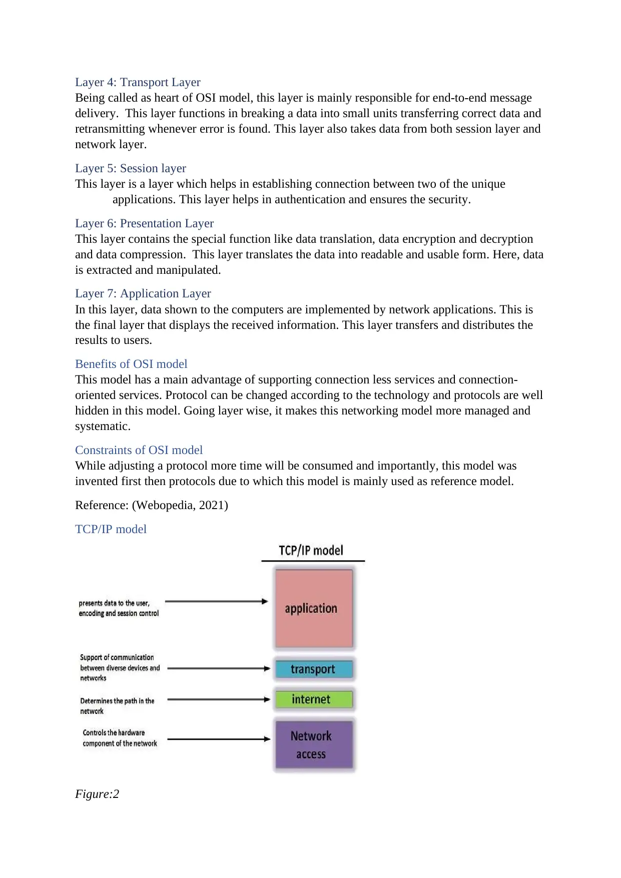
Domain controller (DC)
For our central network, we required a powerful administrative acting server. So, we
configured domain controller for providing the set of rules to the client nodes being
used in our organization. Configuring this service to our central server helped us in
maintaining a good security authentication like logging in, managing permission,
verification of clients across domain etc. Also it provided the active directory and
group policy role for our organization.
Domain name service (DNS)
This service was also configured for our server to take the name of domain and assign
the IP address. This service helped in translating internet domain and host name in IP
address with vice versa relation. It helped in arranging space name goals
administration to web hosts and clients on an IP based network.
Dynamic host configuration protocol (DHCP)
DHCP is a service that helps to assign and provide the unique IP address according to
the address pool of IP given to our organization. Using this service helped a lot for
our network by saving time with providing the IP address automatically to the client.
Assigning IP for each node individually was very time consuming so configuring this
service in our server helps in providing the dynamic IP address of our network
system.
Read-only domain controller (RODC)
RODC service consists Active Directory Database's read only partitions and responds
to security validation requests and it is utilized for reinforcement reason and it is a
duplicate of DC as client can encounter principle DC however with security
verification. We have also used this server for the place where read only facility is
given to the administrator. In our Global IT office, we placed RODC server in one
floor for fast database access.
Child domain controller (CDC)
Child domain by the name is the helping domain of main domain controller also
called as load balancing domain. This server is implemented for working like domain
controller in our office branch. Due to this server, load of main domain was balanced
because of sharing of the domain control activities.
Print server (PS)
This is a type of server that helps in accessing the printer by various clients and nodes
in a network system. Using of this server helped us in printing any sort of required fax
or documents remotely in a connected printer.
DHCP relay agent
This is the server service that helps in distributing the dynamic IP with in the branch
and the head office. This service helped us in creating new interface in different LAN
/branches of Global IT solution. Because of this IP distribution was well managed to
the workstation with in a given starting and ending number of IP.
Windows Deployment Service (WDS)
Windows Deployment Service is a server technology from Microsoft which enables
to install each of the Windows operating systems. It gives the ability to the
administrator to deploy the windows operating system to machine booting from a
network adapter. This service in our server helped for reducing complexity and cost in
comparison to manual installation of programs.
Network components in our design
Network components for our Global IT solution consists different networking devices for
connecting two or more machines within our network for sharing, accessing, transferring files
and folders. Some of the networking devices utilized or used for structuring the system of
Global IT solution are mentioned below:
Firewall
Firewall helped our organization by protecting the devices from the unauthorized
programs or internet users from accessing a private network or single computer. It is
the security device that control the incoming and out coming information and blocked
the unauthorized access. It is the device that give the secure connectivity between
network and protect it from viruses or attacks. Similarly, because of this device we
were able to maintain the good security within our organization.
Switch
Switch is a networking device which is very similar to hub but a little different due to
its work. Switch can also be called as a multiport device like hub. When a sender in
this media sends data then it will move to the switch and switch transfers the data in
exact destination of network using physical address (i.e., MAC). MAC address of
connected nodes will be stored in switch and data is sent wherever required (not in
every port like hub). This medium helped our network by connecting and sharing of
resources between different nodes or clients via Ethernet.
Router
Router is a type of networking device that sends or provides data from one network to
another via IP address. This device mainly functioned in connecting different network
segments for our Global IT company. When data is sent to the router, there will be the
inspection of data’s IP address and finds the path where it is requested. Mainly, due to
the firewall built-in routers are more secured.
Access Point
Access point is a networking medium where both wired and wireless connections are
involved. This device was connected to the wired networking devices for giving a
wireless signal (Wi-Fi) to the needed area in the given organization. Also it provided
the heavily controlled wireless access in the organization.
Testing of design
Herby after the completion of designing a network system for our organization, we then
implemented the design practically. Our company’s required server technology and network
components were installed properly. During our implementation process, we went through
the testing of server with the requirement of our company. We checked the expected and
actual output given by the servers while installing them in our network. Some tests done by
our team for meeting the requirements and checking the functionality of servers are shown
below:
Server testing
s/n Date Server test expected output Actual output
1 5/25/2021 DC Able to give
membership and
security authentication
to all workstation of 40
in an open plan office
All the workstations
were counted as
member of domain and
security policy was
applied
2 5/25/2021 DHCP Must assign the IP
address automatically
to the client/ nodes
Provided individual
dynamic IP to all the
required nodes in entire
network
3 5/25/2021 DNS Provide name in form
of IP address in the
network
Nodes name showed
accurately with the IP
address in network
4 5/25/2021 IIS It has to take the
order of the client
and send required
information to the
client and it also has
to store the content of
the site in the
network design.
It starts to response the
client and provide
the request.
5 5/25/2021 WDS Able to deploy
windows to all clients
Windows were
deployed to all 40
member nodes in a
network
6 5/25/2021 VPN Provide access to the
workstation working
remotely in an
organization
Provided
authentication and
ability to login to the
officer working form
far
7 5/25/2021 RODC Read only access to the
administrator working
in another floor. Also
not able to change
policy of the network
system.
Administrator was able
to see the changes in
data or files of
organization without
editing or modifying
8 5/25/2021 CDC Able to modify the
access and act like
domain controller in
required branches
Acted as domain
controller in Pokhara
and Biratnagar office.
Evaluation:
After the design process we went for the implementation and evaluation process for our
network. Then our team checked the expected as well as actual output of different configured
servers in our network. This testing process made us more confident for the successful
network system establishment. All servers were giving the expected output which was
required for Global IT solution’s network. All the server installed were found to be working
accurately and so on our team moved for the further analysis process of our network system.
Secure Best Marks with AI Grader
Need help grading? Try our AI Grader for instant feedback on your assignments.
Feedback analysis
After testing the configured server, we then move forward for the feedback analysis of well
experienced network system designer and administrator of Golyan Group (Mr. Pawan
Golyan). Feedback helped our team for the required any changes or the evaluation of
networking process in our system. It was an honoured for our team to be checked by well
recognized networking specialist. For analysis process we described and showed him the over
steps and configurations involved in our design. Then a user feedback form was being
provided to Mr. Golyan for the analysing process of our network system. And the evaluation
process was done as per the user definition and requirement.
Feedback form:
Project title: Network design of Global IT solution
Feedback given by: Date: 5/25/2021
Mr. Pawan Golyan Signature: …pawan….
Project description:
This is the network design of Global IT solution including head office and branch office in
Nepal. This design shows the networking components and server technology used for
creating a networking secured network of Global IT solution. This design describes the
working of different networking devices and the connection of different nodes in a main
server. All the branches of this office are connected with head as we can say by the use of
wide area network. Use of VPN and Wireless access point also have been included in our
design and practical process.
Important feature of project : In this project we have used latest devices and
resources. We have maintained higher level of security.
We have connected head and branch office for sharing
important files and resources over the organization.
Checklists Yes No Remarks
Does the network meet the
requirement of scenario
* Yes every requirements are fulfilled
Is the network slow * No it was pretty good
Is requirement of organization
achieved
* Yes it suits for organization very well
Does it have maintained
security
* Yes because of the firewall and routers
it seems more secured
Does system can be modified *
Are server working with actual
functioning properly
* All the servers are doing their
respective work
Feedback evaluated by:
Date
Signature
Global IT solution team
5/25/2021
____Global IT solution_______
Analysis:
According to Mr. Golyan, our network design was working very accurately according to the
requirement of organization. Comparing with the scenario we were able to deal with the basic
need and demand of network system. Our network system was also found to have a fast
workflow. The security system of our network design was also found to be secured and well
maintained. Use of server and their functionality was found to be more clear and systematic
in our network. And our network system is found to be more easy and modification process
can be done effectively.
Although fulfilling the requirement, our system security must be upgraded according to the
time in future. Load balancing can be done more effectively by adding secondary DNS.
Instead of windows server we can replace it with Linux server for better security and
reliability. Therefore, our network design was found to be well functioning and requirement
fulfilling. Then after the network design evaluation process our team moved for the real
implementation or network establishment process.
Conclusion
Our network design for Global IT solution was evaluated by testing of different installed
server and feedback provided for us to the administrator of Golyan Group. After the study,
we found or design to be functioning properly and effectively. Then after the evaluation, we
practically establish the network environment of Global IT solution practically.
Implementation of network system
The actual development process of network system of Global IT solution was then practiced
by our team. We followed all the structure for preparing network connection. We also
maintained the placement of different network devices effectively. Going for the main
practical way we prepared a lab report of installation of required servers in our network
system as per the design.
Lab Report on server configuration
Here this report shows the configuration and installing process of servers and their policies.
Also this report represents the requirements and steps to be followed for installing server
services in our network. Screenshot of result as well as steps are given below in this report
accordingly. (Note: This practice process of configuration of server was done in VMware
Workstation pro and with 2021 server for server including the clients)
Active Directory Domain Service/ Domain Controller (ADDS/DC) report
Domain controller is the server that helps in managing the authentication, group policy, users
and groups in organization etc. This server is also meant to be the administrative acting
server.
Requirements:
1. Windows server
2. Static IP
3. Administrative login
4. Strong password
5. Ram with good performance
6. Enough storage
Procedure for configuring and installing ADDS/DC
Step 1: provide static IP for the network Step 2: Click add roles and features in the
server dashboard
Step 3: select next
Step 4: select add features
Step 1: provide static IP for the network Step 2: Click add roles and features in the
server dashboard
Step 3: select next
Step 4: select add features
Paraphrase This Document
Need a fresh take? Get an instant paraphrase of this document with our AI Paraphraser
Step 5: select the required features to add.
Step 6: Go for the installation process.
Step 7: go to promote the server as domain
Step 6: Go for the installation process.
Step 7: go to promote the server as domain
Step 8: Go to add new forest and provide the domain name
Step 9: apply password for the domain for login process.
Step 10: provide the NetBIOS domain name if necessary (optional)
Step 9: apply password for the domain for login process.
Step 10: provide the NetBIOS domain name if necessary (optional)
Step 11: Click next for 2 time and there will be prerequisite check for the domain
Step 12: login with the provided IP and you will be logged in as the given domain name.
Domain Name System (DNS) report
This service was also configured for our server to take the name of domain and assign the IP
address. This service helped in translating internet domain and host name in IP address with
vice versa relation. It helped in arranging space name goals administration to web hosts and
clients on an IP based network.
Requirements:
1. ADDS/DC should be installed
2. Administrative login
3. Static IP
4. Proper domain name
Procedure for configuring and installing DNS
Secure Best Marks with AI Grader
Need help grading? Try our AI Grader for instant feedback on your assignments.
Step 1: Go to add roles and features like ADDS.
Step 2: click next for 3 times and select the DNS function
Step 3: After installing feature of DNS, go to tools and select DNS
Step 2: click next for 3 times and select the DNS function
Step 3: After installing feature of DNS, go to tools and select DNS
Step 4: Apply next
Step 5: select the second option
Step 6: Lookup zone is being created.
Step 7: select the reverse zone and select new zone
Step 5: select the second option
Step 6: Lookup zone is being created.
Step 7: select the reverse zone and select new zone
Step 8: Select next with selection of primary zone
Step 9: After next select second option
Step 10: select the IpV4 option
Step 9: After next select second option
Step 10: select the IpV4 option
Paraphrase This Document
Need a fresh take? Get an instant paraphrase of this document with our AI Paraphraser
Step 11: Provide the IP address of DNS
Step 12: finish the process and finalize
Step 13: Then select the zone to add new host and give the www name.
Step 14: new host will be created by according to given name.
Internet Information Services (IIS) report
This server software consists the main purpose of hosting websites and other content on the
web. Search on the web by IP given by ADDS or domain name helps in displaying the file
contents of organization.
Requirements:
1. Installation of domain controller
2. Configuration of DNS
3. Administrative login
Procedure for configuring and installing IIS
Note: same beginning process of adding roles and features like in DNS or Domain.
Step 1: select the required role i.e. Web Server(IIS)
Step 2: Select the role required for IIS.
Step 3: Click install for applying the service to server
Step 2: Select the role required for IIS.
Step 3: Click install for applying the service to server
Step 4: after installation go to IIS from tools option
Step 5: Create html file to be loaded in web server
Step 6: after creating file go to IIS from tools and click add website option.
Step 7: Give the site name and the IP address
Step 5: Create html file to be loaded in web server
Step 6: after creating file go to IIS from tools and click add website option.
Step 7: Give the site name and the IP address
Secure Best Marks with AI Grader
Need help grading? Try our AI Grader for instant feedback on your assignments.
Step 8: Delete the default documents from the site name.
Step 9: add the html file and in directory browsing enable it.
Step 10: then go to internet browser and search the site by DNS name or IP address and it
gives the value of html file that have been attached.
Dynamic host configuration protocol (DHCP) report
DHCP is a service that helps to assign and provide the unique IP address according to the
address pool of IP given to our organization. Using this service helps a lot to network by
saving time with providing the IP address automatically to the client. Assigning IP for each
node individually was very time consuming so configuring this server helps in providing the
dynamic IP address to network system.
Requirements:
1. Domain controller authorization
2. Static IP with DNS name
3. IP parameters must be well known
4. Installation of DHCP server
Procedure for installing and configuring DHCP
Note: Same beginning process until feature selection like DNS and ADDS
Step: Select DHCP services from selection
Step: Install the server facility.
Step: Select the complete configuration from notification
4. Installation of DHCP server
Procedure for installing and configuring DHCP
Note: Same beginning process until feature selection like DNS and ADDS
Step: Select DHCP services from selection
Step: Install the server facility.
Step: Select the complete configuration from notification
Step: After clicking next for once provide user name and select commit button.
Select DHCP from the tools feature from dashboard
Select the IPV4 and select new scope
Select DHCP from the tools feature from dashboard
Select the IPV4 and select new scope
Paraphrase This Document
Need a fresh take? Get an instant paraphrase of this document with our AI Paraphraser
Provide the start IP address and end IP address
After clicking next for twice you can reach to the time lease duration of given IP
Then provide Parent domain name and server name including the IP of domain.
After next finish the process of configuring DHCP server
After clicking next for twice you can reach to the time lease duration of given IP
Then provide Parent domain name and server name including the IP of domain.
After next finish the process of configuring DHCP server
DHCP relay agent report
This is the server service that helps in distributing the dynamic IP with in the branch and the
head office. This service helps in creating new interface in different LAN /branches of any
big organization. Because of this IP distribution was well managed to the workstation with in
a given starting and ending number of IP.
Requirements:
1. DHCP services must be installed
2. Administrative login
3. Address pool must be known
4. Branches of organization for huge IP distribution
Procedure for installing and configuring DHCP relay agent
Note: same process until the selection of server service
Select the remote access option
The add the features accordingly for DHCP relay agent
Go for the installation process of DHCP relay agent.
Select the DHCP relay agent from the tools facility.
Right click server and select configure and enable option.
Select the custom configuration option
Select the DHCP relay agent from the tools facility.
Right click server and select configure and enable option.
Select the custom configuration option
Secure Best Marks with AI Grader
Need help grading? Try our AI Grader for instant feedback on your assignments.
Select the LAN routing option and next
Finish the process of setup
Then select general from IPV4 option and new routing protocol from general option.
Select the DHCP relay agent and ok
Finish the process of setup
Then select general from IPV4 option and new routing protocol from general option.
Select the DHCP relay agent and ok
Right click on DHCP Relay Agent and select new interface.
Select the Ethernet option then.
Select properties from the DHCP relay agent with right click
Give the IP address of server and then Ok
The output after configuration of DHCP relay agent.
Select the Ethernet option then.
Select properties from the DHCP relay agent with right click
Give the IP address of server and then Ok
The output after configuration of DHCP relay agent.
Showing the IP address result by the server.
Virtual private network (VPN) report
Virtual Private Network is a private network which is used to transfer the data by creating the
safe tunnel and hide the IP address safely. It is the service which gives the permission to
client for accessing to the workplace remotely. VPN also helps to extend corporate network
through encrypted connections made over network. Data travels safely because of data
encryption.
Requirements:
1. Client must take IP provided by DHCP
2. Permission from administrator
3. Connection to the workplace
4. Remote access must be enabled
Procedure for installing and configuring VPN service
Note: same beginning step of above process like ADDS until the service selection
Select the remote access feature and select next.
Select the first two option and next
Paraphrase This Document
Need a fresh take? Get an instant paraphrase of this document with our AI Paraphraser
Start the installation process after adding the feature
After installation, select the routing and remote access from tools option
Right click the local server and select configure and enable option
Select the custom configuration process and next
After installation, select the routing and remote access from tools option
Right click the local server and select configure and enable option
Select the custom configuration process and next
Select the VPN access option and next and finish the process.
Select the server and go for the properties after the above setup
Click on IPV4 then tick mark on static address and provide the IP address finally with
selecting apply.
Print server report
This is a type of server that helps in accessing the printer by various clients and nodes in a
network system. Using of this server that functions in printing any sort of required fax or
documents remotely in a connected printer.
Requirements:
1. Installation of Print server
2. Access of using a printing device with server
Procedure for installing Print server services
Note: Starting process until selection of feature are same as ADDS
Select the services to be configured i.e. Print Server
Select the Print server after the adding of feature.
Install the services after confirmation process by applying next and install
Secure Best Marks with AI Grader
Need help grading? Try our AI Grader for instant feedback on your assignments.
After installation select the Print management from tool
After entering select the server name and select add printer
After applying next then add the new printer on existing port or according to condition.
Then select the option to install a new driver
After entering select the server name and select add printer
After applying next then add the new printer on existing port or according to condition.
Then select the option to install a new driver
After doing next, select the manufacturer and printers model and next.
Select on option share printer and ok
Right click on printer then select Deploy with group policy.
Select on option share printer and ok
Right click on printer then select Deploy with group policy.
Click on browse then select the policy.
Tick mark on both Domain Connection then click on ok.
Final result after the installation and configuration of printer server.
Windows deployment server (WDS)
Windows Deployment Service is a server technology from Microsoft which enables to install
each of the Windows operating systems. It gives the ability to the administrator to deploy the
windows operating system to machine booting from a network adapter. This service when
installed in server helps for reducing complexity and cost in comparison to manual
installation of programs.
Requirements:
1. IP assigned to client by DHCP
2. Control of administrator
3. Clients with the windows 7
Procedure for installing and configuring WDS
Note: Starting process until selection of feature are same as ADDS
Paraphrase This Document
Need a fresh take? Get an instant paraphrase of this document with our AI Paraphraser
Add role specifically as named Remote Server Administration tool.
Select both role service and select next button
Go for the installation process by simply clicking install.
Select both role service and select next button
Go for the installation process by simply clicking install.
Select the windows deployment services from tools.
Right click on local server then select configure server and click next.
Tick mark on 1st option then click on next.
Select both option and apply next.
Right click on local server then select configure server and click next.
Tick mark on 1st option then click on next.
Select both option and apply next.
Select respond option and go for next.
Enter the name for image group.
Go to boot image and right click then select add boot image.
Enter the name for image group.
Go to boot image and right click then select add boot image.
Secure Best Marks with AI Grader
Need help grading? Try our AI Grader for instant feedback on your assignments.
Click on browse and select the boot.wim.
Again click on browse and select the install.wim.
Select new virtual machine and open the windows.
Child Domain Controller (CDC)
Child domain by the name is the helping domain of main domain controller also called as
load balancing domain. This server is implemented for working like domain controller in our
office branch. Due to this server, load of main domain is balanced because of sharing of the
domain control activities.
Requirements:
1. Installation of ADDS
2. Administrative login
3. Must take IP from the DHCP
4. If network administrator required for the branches
Procedure for installing and configuring CDC
1. Select the server manager then click
on Add roles and features.
2. Select the role based or feature based
installation then click on next.
3. Select the ADDS then add features. 4. Tick mark on restart then click on
install.
5. Click on yellow flag then select
promote this server to DC
6. Tick mark on 2nd option and type
new domain then click on next.
7. Enter restore mode password then
click on next.
8. Click on install button and select
finish.
9. Click on the close button. 10. Result of CDC server.
11. Result shown for CDC server.
Read Only domain controller(RODC)
RODC service consists Active Directory Database's read only partitions and responds to
security validation requests and it is utilized for reinforcement reason and it is a duplicate of
DC as client can encounter principle DC however with security verification. This server is
used for the place where read only facility is given to the administrator.
Paraphrase This Document
Need a fresh take? Get an instant paraphrase of this document with our AI Paraphraser
Requirement:
1. Installation of ADDS
2. Administrative login
3. Permission from the main domain controller
4. If to provide read only option for small administrator
Procedure for installing and configuring RODC
1. Click on the Server manager then
select Add features.
2. Select Role based or feature based
installation then click ok next.
3. Select ADDS then click on add
features. 4. Tick mark on the restart then click
on install button.
5. Click on promote this server to
Domain Controller
6. After choosing add a new domain,
Enter password then click ok.
7. Tick mark on 3rd option then enter
restore mode password and click next.
8. Click on install.
Here is the result of RODC server:
9. Result of RODC server. 10. Result of RODC server.
Test result against expected result
Hereby, after a practical implementation session we move on for testing of the encountered
result by comparing with expected one. This helped in getting result of whether configuration
and installation process is done successfully or not. Below we also have submitted the final
result in the form of screenshot done in VMware. Below comparison also shows whether our
network design in implemented properly or not. The provided screenshot represents the
evidence for our network.
What was tested: IP address of the main domain in
network is static or not
Expected Output Actual Output
Typing ipconfig in command prompt displays the
static IP of a network
Static IP was displayed which was
used by the Domain controller of
network
Evidence:
What was tested: administrative login to
domain controller
Expected Output Actual Output
Administrator being able to log in to the
domain controller of organization
Administrative log in was seen after
installation of ADDS successfully
Evidence:
What was tested: IP distribution by DHCP
or not
Expected Output Actual Output
Dynamic IP must be assigned to the clients
or workstations
Client was assigned an IP by DHCP while
checking in server
Evidence:
What was tested: DHCP relay agent
Expected output Actual output
Clients must take IP address according to
the respective LAN
Clients of branches and head office were
assigned different IP according to the DHCP
Evidence:
What was tested: IF RODC is configured or
not
Expected output Actual output
Read only facility for branch administrator Administrator can only open and read the
files of the server
Secure Best Marks with AI Grader
Need help grading? Try our AI Grader for instant feedback on your assignments.
Evidence:
What was tested: Web server
configuration/IIS
Expected Actual
Show of files in website by searching with
domain name or IP address.
The content was shown in the site by
searching with name of domain and IP
Evidence:
What was tested: Can client access to the
workplace using VPN service
Expected Actual
Client must be able to connect with
workplace remotely and wirelessly
Client was able to connect with workplace
and login remotely from separate node
because of VPN
Evidence:
What was tested: DNS server
Expected Actual
Must provide the assigned static IP while
asking for the Ip showing process
Was able to show the actual assigned IP for
the domain system
Evidence:
What was tested: print server access
Expected Actual
The printer device must be shown in the
client server while typing the IP address in
run.
As per expected
Evidence:
Conclusion
Before the final step up of network was done, we went through all the lab reports, design
check and comparison of requirements along with the configured servers. The above task
clearly shows the working framework for our designed network for Global IT solution.
Maintenance schedule
After the lab process then our team work for the maintenance process of the network system.
Below is the proper schedule of maintenance in network system by our team:
S.N Maintenance task Start date End date Time
Day 1
1 Physical equipment check 5/29/2021 5/29/2021 1 hour
2 ADDS check 5/29/2021 5/29/2021 1 hour
3 Framework log check 5/29/2021 5/29/2021 2 hours
4 Ping test 5/29/2021 5/29/2021 45 min
5 Check the IP lease duration
by DHCP to clients
5/29/2021 5/29/2021 1 hour
Day 2
6 Managed the network cables 5/30/2021 5/30/2021 1 hour
7 Configure Kaspersky
antivirus
5/30/2021 5/30/2021 1.2 hour
8 Scanned the entire system and
remove viruses
5/30/2021 5/30/2021 1.5 hours
9 Configured firewall and port
security
5/30/2021 5/30/2021 1.5 hours
10 Check the networking devices
working properly or not
5/30/2021 5/30/2021 30 min
Day 3
11 Check the RODC server
properly
5/31/2021 5/31/2021 20 min
12 Backup the domain controller 5/31/2021 5/31/2021 45 min
13 Check the users and group
authentication
5/31/2021 5/31/2021 15 min
14 Security check 5/31/2021 5/31/2021 2 hours
15 Check all the server finally 5/31/2021 5/31/2021 1.5 hours
While maintaining process we encountered various errors and problems that occurred in
network system of Global IT solution. We then critically solved the problem and make the
system error free. Firstly, we faced the problem that DHCP server didn’t provide d the IP
properly to the clients. We then brought up a solution to it by checking the clients and
network segments and DHCP server properly. Secondly, we also found there was some sort
of virus in network system. We were able to deal with it by configuring the antivirus and
removing the virus successfully. There was also some connection problem due to the
loosening of cables and we manage to fix the cables properly and defeat this problem. While
maintenance of port security we configured the firewall protection and make it secured. There
was also not proper backup of domain controller and while this phase we backed up the
domain controller.
Therefore, maintenance process helped us in finding out some major components effecting
the network system and deal with it. Importantly, maintenance is equally needed for any
network system for better improvement of system. Also our team would compulsorily
recommend for time to time maintenance of network for betterment.
Recommended potential enhancement for network system
Successful design and the experiment process of the network system was checked and
finalized for implementation. Above there have already mentioned the testing and
implementation process for network system of Global IT solution.
Although being a well-managed and professional network that fulfil the requirements of
organization, there have been certain lack in system for being the well secured and perfect
network system. Though our designed and implemented network system was secured but if
Paraphrase This Document
Need a fresh take? Get an instant paraphrase of this document with our AI Paraphraser
we had used Linux operating system it would have been more secured. Also Linux operating
system is found to be more flexible and reliable rather than windows operating system. While
our network design process we have used simple switch for connection of server and nodes
and also with wireless access. Instead of simple switch using cisco switch would have been
faster data transmission and in build security but contrasting the budget highly. Using
biometrics facility seemed to be more expensive for the implementation process but it would
help in maintaining the high security level. Using biometrics would have kept our network
system more secured by letting the only authorized person to access the network services in
organization.
During the process of building network system, we used the pirated software (VMware) for
networking. If we would have used non pirated software, then it would have been easier in
configuration of server and services process. And we could have use all the facilities and
features as well as tools provided by the software. We also recommend for using the latest
computers for the network for high processing and less time consuming processing. Using
CC TV monitoring also will help in maintaining the security level in organization. Unknown
staffs or acts can be visualized by the use of CCTV in workplace.
Critical evaluation of project
Here evaluation of the network design with implementation including negative and positive
aspect is described. Recommendation for further development is also been described below
critically.
Network design
Therefore, our task was to design the network system for Global IT solution. During our
design process we first evaluate the requirements properly and designed the network
architecture according. Being a first task it was a bit problematic and confusing for our team
members but according to the research and case study we were able to make a network
architecture for Global IT solution. During our design process, we used the star topology
model for. Using this topology, we managed to evaluate the best server for centralized
networking process. In our design we have shown the servers and the connection of central
server to the nodes in a network. We have also shown the wireless access connection to the
main server with the help of switch. Routers and firewalls have been used for the data
transmission which made our network system more secured. Child domain and Read only
domain controllers were configured in a respective server for the branch offices. There we
also have maintained the load balancing of server by installing different server in a network
system. Use of proper VPN tunnelling for head and branch office are clearly mentioned in
our design. Overall, our design represents the essential components and proper networking
system for Global IT solution (also can be helpful for other organizations).
Test plan of the design
After the design process we went through various practical testing and feedback evaluation
for the given network. After the designing process our team firstly checked the server
working as per expectedly or not. We created a table where our servers installed are working
properly or not. After getting all the expected result from the server services we then move
forward for the user feedback. Mr. Golyan form Golyan Groups helped us in checking the
system and the requirements meetup. There we provided the feedback form with some
questionaries’ related to our network design. Our design was found to be more practical and
effective after analysing the feedback. Feedback from user perspective was found to be more
convenient for our designed system. Various testing of RODC, DC, WDS, CDC, Print server,
etc. were tested practically and systematically in this phase of network development process.
Implementation of design
After the testing process of expected output and servers, our team then after move for the
actual implementation process of network system. Here we configured and installed different
required servers and facilities for network. Also the lab report of implementation process is
shown above. Because of testing and feedback we were able to work smoothly for the actual
designing process of Global IT’s network. We installed DC, RODC, CDC, Print server,
WDS, VPN, DNS and IIS servers that are essential for the network system. Also we checked
the demanded and actual output for the network. Therefore, the final network system of
Global IT solution was established by testing of design and evaluation of feedback from
senior administrator.
Positive aspect of designed network
After the implementation process we checked for the positive aspect of our designed network.
Our network as per requirement provided the centralized network with powerful server. Our
design followed the client server architecture. Our network system was found to be accurately
centralized. Client in this network ask for the files and the documents to the main server and
data is accessed through it. This centralized server makes our network more accurate and fast.
In our designed network, administrator can provide the log on and log off hours for users that
makes network more systematic and disciplined. Flow of information or files is fast in our
network system because of central server. Load balancing is also structured properly within
the system.
Negative aspect of designed network
As, our system also consists of some negative impacts. One major impact is when a central
server is down then the entire network will be affected. For implementation this designed is
also found to be costlier because there are number servers, devices installed. Any attack on
central server will be very deadly in this system because all the resources is stored in the
central server. Although we have used the cisco routers but those were not the very latest
ones so there was less feature available for network developers. There is also installation of
firewalls but in less. All the network system is controlled by the single administrator so it can
also be riskier in data leakage. Highly skilled manpower is required for maintenance purpose
of this network.
Recommendation for future improvements
Therefore, our design helped in structuring the network system of Global IT solution. There
is some more recommendation from our team for the further development of system. Firstly,
replacing the old devices with latest device is really important in order to maintain the high
performance level. Use of biometric system and non-pirated software must be implemented
during the future development. Installing of optional DNS is also required for the increasing
number of clients. The old server must be replaced if the clients are increased drastically.
Using of cisco switch must be implemented for the better data transmission process in
network. Our team will also recommend for using the latest devices and nodes for faster and
secure processing. We also recommend is focusing for the system security mainly while
implementing process. Importantly, maintenance process is also a major component to be
recommended by our team.
Conclusion
Therefore, our network system was established by following various steps and procedure. For
successful networking the evaluation process is also equally important. Maintenance, being
up to date will help any sorts of network system for development process. Above is the brief
description of practical as well as evidential process to go for successful network system
development.
References
BegineersBook. (n.d.). BegineersBook. Retrieved from www.BegineersBook.com:
https://beginnersbook.com/2019/03/introduction-to-computer-
network/#:~:text=A%20computer%20network%20is%20a,other%20devices%20over%20the
%20network.
Bourgeois, S. (n.d.). Belden. Retrieved from www.Belden.com:
https://www.belden.com/blogs/network-types
Essay[ZZ..]. (2021). esssay[ZZ..]. Retrieved from esssayzz.com: <https://essayzz.com/essays/p1-
discuss-the-benefits-and-constraints-of-different-network-types-and-standards/
Guru99. (n.d.). Retrieved from Guru99.com: https://www.guru99.com/tcp-ip-
model.html#:~:text=Summary:%201%20The%20full%20form%20or%20TCP/IP%20model,hig
hest%20level%20of%20OSI%20model.%20More%20items
studytonight. (2018). Retrieved from studytonight.com: https://www.studytonight.com/computer-
networks/network-topology-types
Webopedia. (2021). Retrieved from www.Webopedia.com:
https://www.webopedia.com/reference/osi-layers
Yong. (n.d.). slideshare. Retrieved from slideshare.net:
https://www.slideshare.net/makyong1/chapter-33-12564245?qid=685779cb-d112-4f28-
88bc-8f4d3c99404c&v=&b=&from_search=26
1 out of 70
Related Documents
Your All-in-One AI-Powered Toolkit for Academic Success.
+13062052269
info@desklib.com
Available 24*7 on WhatsApp / Email
Unlock your academic potential
© 2024 | Zucol Services PVT LTD | All rights reserved.