logo

Analysis of Various Forces Stresses Assignment

Design of a rotor shaft for the Applied Solid Mechanics and Dynamics course at Sheffield Hallam University.

7 Pages1071 Words15 Views
   

Added on  2022-08-26

Analysis of Various Forces Stresses Assignment

Design of a rotor shaft for the Applied Solid Mechanics and Dynamics course at Sheffield Hallam University.

   Added on 2022-08-26

ShareRelated Documents
Introduction
Analysis of various forces, stresses and strains acting on components to be used in daily
operations of human life is an important aspect since it gives the engineer time to design and
analyze the possible failure of the component. From the design and analyzes he/she is able to
design a component whose failure rate is low thus minimizing risks that leads to accidents for
instance in the helicopter. It also helps in minimizing possible losses that might occur if the
designed and fabricated component fails or its failure to withstand forces leading to the need
of redesigning and developing a new component. Torque, bending moments, induced stresses
and strains should always be analyzed before fabrication of the component. (Johnstonn,
2006) This also raises the need for a safety factor to cater for extra forces that might be
induced during normal operations of the component.
(a) Calculation of direct and shear stress acting on the 2-D element
Numerical data
M- Bending moments is 3.6KNm and 2.5KNm = 6.1KNm
e- eccentricity is 15mm
T- torque
F-force is 50KN
61 and 62 - stress
F= T 2M 2
1 +F1
T = MJ
I =
6.1 × 10⁶π
32 ( D4d4 )
π
64 ( D4 d4 )
=12.2 ×10⁶ Nmm
Therefore: F= (12.2× 10⁶ )2(6.1 ×10⁶ )2
1 + 5.0×106 = 13.65 ×10⁶
Where I is the moment of inertia and J is the polar moment of inertia
P= F
A = 13.6 5× 10⁶
π
4 ¿ 402
=10860.91 Nm m2
Where P isthe pressure A is the areaacted upon by pressure
Then 6Ѳ= PD
2 t =10860.91 × 40
2× 5 =¿ 43443.64N/mm
Analysis of Various Forces Stresses Assignment_1
6z = PD
4 t =10860.91 × 40
4 × 5 =¿ 21721.82N/mm
Ʈxy= 6.1× 106 × 25
π
64 ( 504404 )
=841.816 N /mm2
61,62 =
6 Ѳ+ 6 z
2 ± 1
2
(6 z6 Ѳ)2+ 4 Ʈxy2
1 =32582.73+ 43443.64
2 ± 1
2
(32582.734 3443.64)2 +4 (841.816)2
1
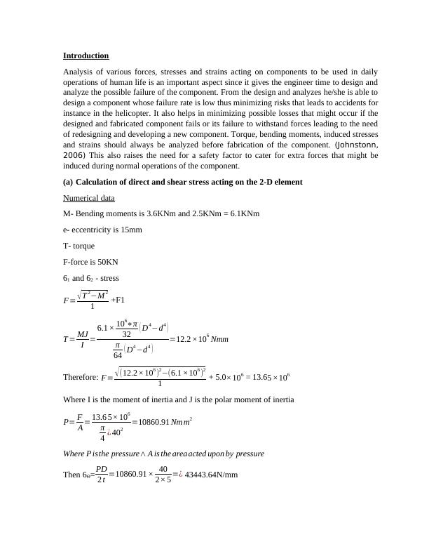
Thus 61 = 38013.185 + 5495.32 = 43508.505N/mm
62 = 38013.185 – 5495.32 = 32517.865N/mm
Then maximum shear stress(Ʈmax) =
1
2
(6 z6 Ѳ)2+ 4 Ʈxy2
1 =1
2
(32582.733443.64)2+ 4 (841.816)2
1 =5495.32 N / mm
CITATION DrT12 \l 1033 (MEGSON, 2012)
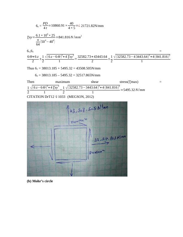
(b) Mohr’s circle
Analysis of Various Forces Stresses Assignment_2
(Ibrahim, 2013)
From the diagram, principal stresses are
Max principal stress = N = 59.4N
Min principal stress = M = -13N
Max shear stress = Ʈmax = 3.78
Angle = 1
2 × φ= 1
2 × 47=23.5°
(c) From the formulae principal stress are
Max principal = 61 =
6 Ѳ+ 6 z
2 + 1
2
(6 z6 Ѳ)2 + 4 Ʈxy2
1 = 50+3.6
2 + 1
2
(503.6)2 + 4(2.5)2
1 =50.1343 KNm
CITATION RCH09 \l 1033 (Hibbeler, 2009)
Analysis of Various Forces Stresses Assignment_3

End of preview

Want to access all the pages? Upload your documents or become a member.

Related Documents
Engineering Mechanics | Report
|14
|2338
|36