Comparative Study of AM and FM Modulation Techniques
VerifiedAdded on 2020/05/28
|18
|2426
|90
AI Summary
In this study, we delve into amplitude modulation's fundamental principles by examining signal behavior through experimental analysis using a spectrum analyzer (Rhode & Schwarz HMS-X), oscilloscope (Keysight Infiniivision DSO-X 2002A), and waveform generator (Keysight 33500B). By varying the carrier frequency at 500 kHz with modulating frequencies set at 50 kHz, modulation depths were adjusted to 30%, 40%, and 50%. The experiment scrutinizes how these changes influence sideband visibility and spectrum characteristics. We observed that reducing the amplitude of the modulating signal below a modulation index of 0.3 results in only one observable sideband due to low modulation depth. Conversely, increasing the modulation amplitude causes significant reduction or invisibility of certain spectral components like J0m in the analyzer. This assignment highlights the correlation between theoretical predictions and empirical findings regarding AM's behavior, noting minimal discrepancies attributed to measurement errors. The comparative analysis of AM with frequency modulation underscores FM’s superior noise resistance despite its broader bandwidth, emphasizing its effectiveness over AM in various applications.
Running head: AM AND FM EXPERIMENT 0
AM AND FM EXPERIMENT
Name of Student
Institution Affiliation
AM AND FM EXPERIMENT
Name of Student
Institution Affiliation
Paraphrase This Document
Need a fresh take? Get an instant paraphrase of this document with our AI Paraphraser
AM AND FM EXPERIMENT 2
AIM
To compare and contrast the amplitude modulation and Frequency modulation for both the
frequency domain and time domain.
Introduction
In a radio system, there are higher frequency signals of the sinewave which are modulated by
a message signal. These signals are as well referred to as carrier wave. This is achieved through
modulating it with a signal having a relatively lower frequency. This is very important because it
is challenging to convey the message signal in a straight line from the transmitter to the receiver.
Modulating signal may vary in three different types. All the types of the modulation are analog
and are employed in the transmission of the signal through wireless. And for any analog
modulator, there is always two input with just one output. These two inputs are the carrier signal
waveform and the analog signal to be transmitted while the output is the modulated output. We
will hence discuss these two types of modulations;
1. Frequency Modulation (FM)
2. Amplitude Modulation ( AM)
AM AND FM EXPERIMENT 3
Frequency Modulation (FM)
In this form of modulation the carrier frequency changes due to the analog baseband
info signal ready to be conveyed via wireless devices. This modulation is essentially treated to be
better than the AM because it of better noise immunity it has and its capacity to reject the
interfering signals because of the capture effect. The equation below help to obtain modulation
depth
m= Δf
fm ……………………………………………………………………………………..i
Where Δf is the frequency deviation and fm is the frequency of the modulating signal.
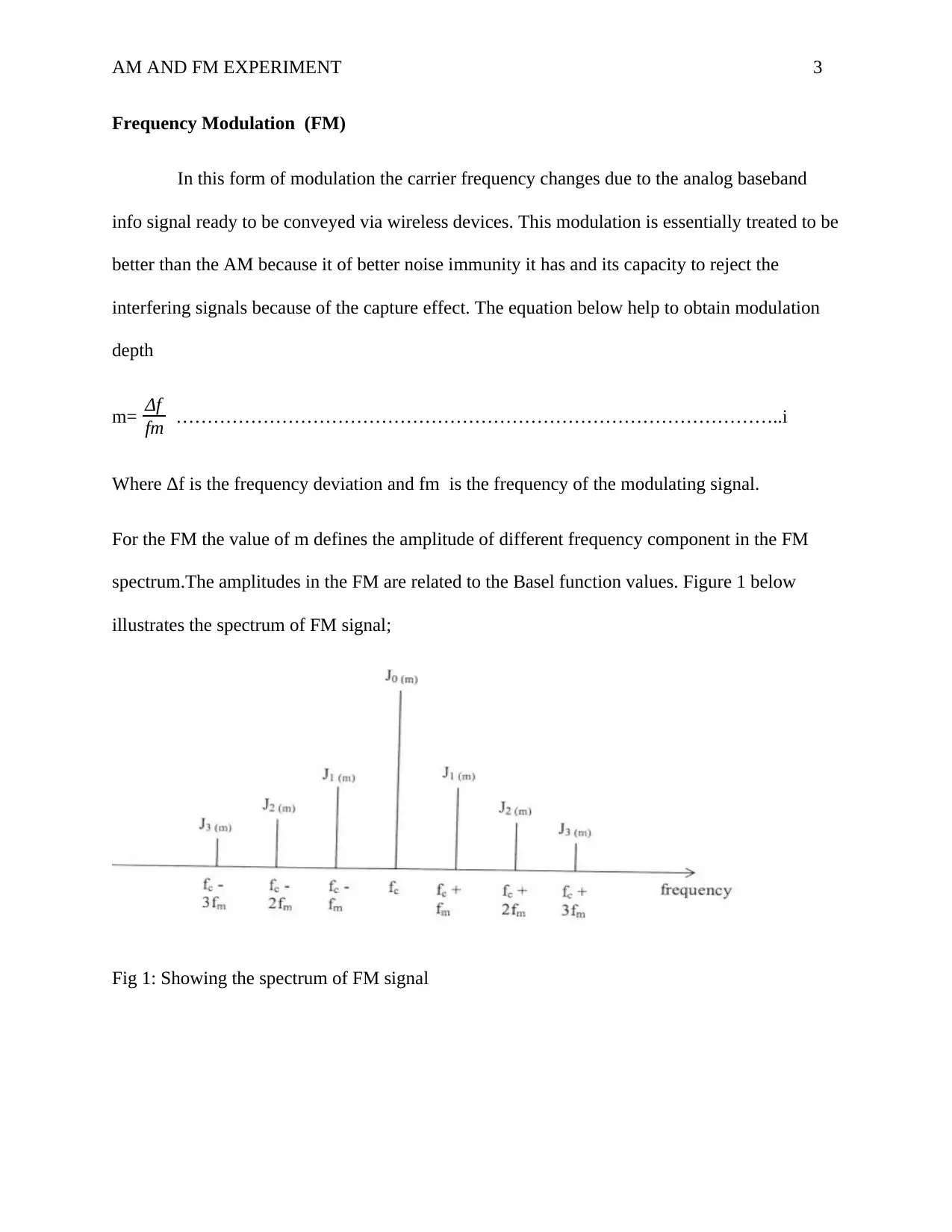
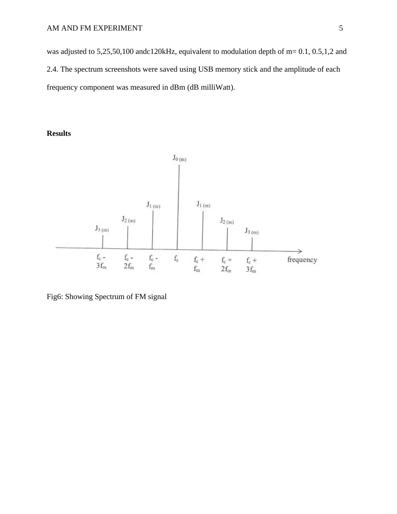
For the FM the value of m defines the amplitude of different frequency component in the FM
spectrum.The amplitudes in the FM are related to the Basel function values. Figure 1 below
illustrates the spectrum of FM signal;
Fig 1: Showing the spectrum of FM signal
⊘ This is a preview!⊘
Do you want full access?
Subscribe today to unlock all pages.

Trusted by 1+ million students worldwide
AM AND FM EXPERIMENT 4
The utmost common technique of applying modulation to a signal is by overlaying the audio
signal onto the amplitude of the carrier. When employing frequency modulation, extra advancements in
signal to noise ratio can be realized only if the audio signal is stressed. To obtain this there must be an
amplification of lower level high frequency sounds to a higher degree than the lower frequency sounds
before they are conveyed. As soon as the receiver the signals are passed via a network with the reverse
effect to reinstate a flat response frequency.
The transmitter and receiver networks must match one another. For broadcasting in North
America values of 75μs with a break frequency of 2.1 kHz is used. Frequency modulation is used in a
wide variety or radio communications applications from broadcasting to two-way radio communications
links as well as mobile radio communications. It possesses many advantages over amplitude modulation
and this is the reason for its widespread use. Nowadays, many digital forms of radio communications are
being introduced, but despite this the use of frequency modulation, FM will undoubtedly continue for
many years to come in many areas of radio communications.
Equipment
1. Spectrum Analyser- Rhode & Schwarz HMS-X
2. Oscilloscope- Keysight Infiniivision DSO- X 2002A, 70 MHz, 2GGSa/sec, Digital
Storage Oscilloscope (DSO).
3. Waveform Generator – Keysight 33500B.
Procedure
A carrier frequency of 500 kHz for the modulated and frequency of the 50 kHz audio signal. The
amplitude of the FM signal was confirmed that it was not varying. The deviation of frequency
Paraphrase This Document
Need a fresh take? Get an instant paraphrase of this document with our AI Paraphraser
AM AND FM EXPERIMENT 5
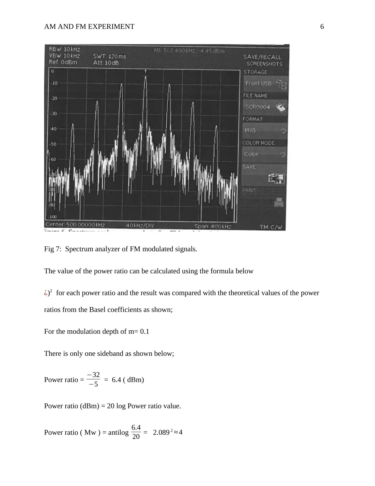
was adjusted to 5,25,50,100 andc120kHz, equivalent to modulation depth of m= 0.1, 0.5,1,2 and
2.4. The spectrum screenshots were saved using USB memory stick and the amplitude of each
frequency component was measured in dBm (dB milliWatt).
Results
Fig6: Showing Spectrum of FM signal
was adjusted to 5,25,50,100 andc120kHz, equivalent to modulation depth of m= 0.1, 0.5,1,2 and
2.4. The spectrum screenshots were saved using USB memory stick and the amplitude of each
frequency component was measured in dBm (dB milliWatt).
Results
Fig6: Showing Spectrum of FM signal
AM AND FM EXPERIMENT 6
Fig 7: Spectrum analyzer of FM modulated signals.
The value of the power ratio can be calculated using the formula below
¿)2 for each power ratio and the result was compared with the theoretical values of the power
ratios from the Basel coefficients as shown;
For the modulation depth of m= 0.1
There is only one sideband as shown below;
Power ratio = −32
−5 = 6.4 ( dBm)
Power ratio (dBm) = 20 log Power ratio value.
Power ratio ( Mw ) = antilog 6.4
20 = 2.089 2 ≈ 4
⊘ This is a preview!⊘
Do you want full access?
Subscribe today to unlock all pages.

Trusted by 1+ million students worldwide
AM AND FM EXPERIMENT 7
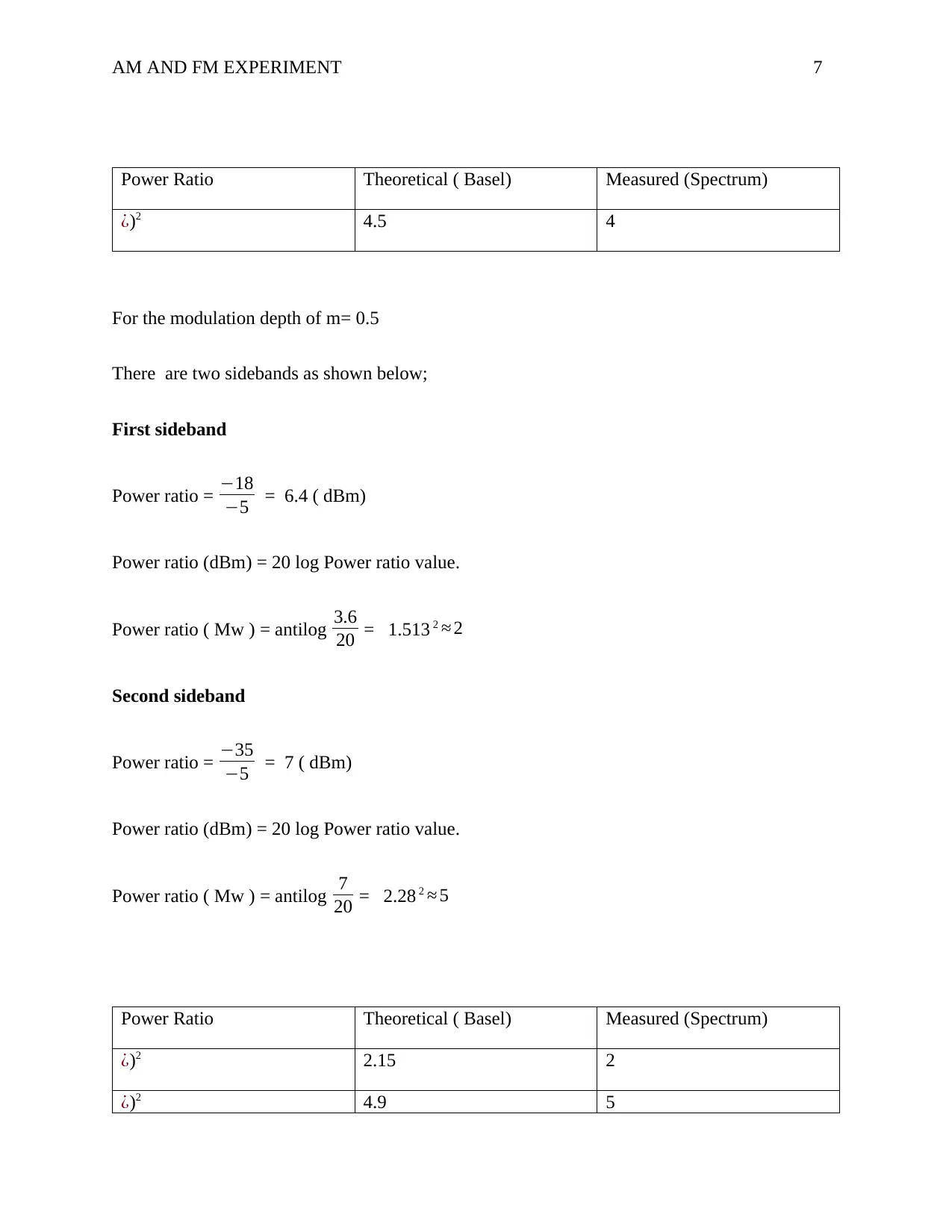
Power Ratio Theoretical ( Basel) Measured (Spectrum)
¿)2 4.5 4
For the modulation depth of m= 0.5
There are two sidebands as shown below;
First sideband
Power ratio = −18
−5 = 6.4 ( dBm)
Power ratio (dBm) = 20 log Power ratio value.
Power ratio ( Mw ) = antilog 3.6
20 = 1.513 2 ≈ 2
Second sideband
Power ratio = −35
−5 = 7 ( dBm)
Power ratio (dBm) = 20 log Power ratio value.
Power ratio ( Mw ) = antilog 7
20 = 2.28 2 ≈ 5
Power Ratio Theoretical ( Basel) Measured (Spectrum)
¿)2 2.15 2
¿)2 4.9 5
Power Ratio Theoretical ( Basel) Measured (Spectrum)
¿)2 4.5 4
For the modulation depth of m= 0.5
There are two sidebands as shown below;
First sideband
Power ratio = −18
−5 = 6.4 ( dBm)
Power ratio (dBm) = 20 log Power ratio value.
Power ratio ( Mw ) = antilog 3.6
20 = 1.513 2 ≈ 2
Second sideband
Power ratio = −35
−5 = 7 ( dBm)
Power ratio (dBm) = 20 log Power ratio value.
Power ratio ( Mw ) = antilog 7
20 = 2.28 2 ≈ 5
Power Ratio Theoretical ( Basel) Measured (Spectrum)
¿)2 2.15 2
¿)2 4.9 5
Paraphrase This Document
Need a fresh take? Get an instant paraphrase of this document with our AI Paraphraser
AM AND FM EXPERIMENT 8
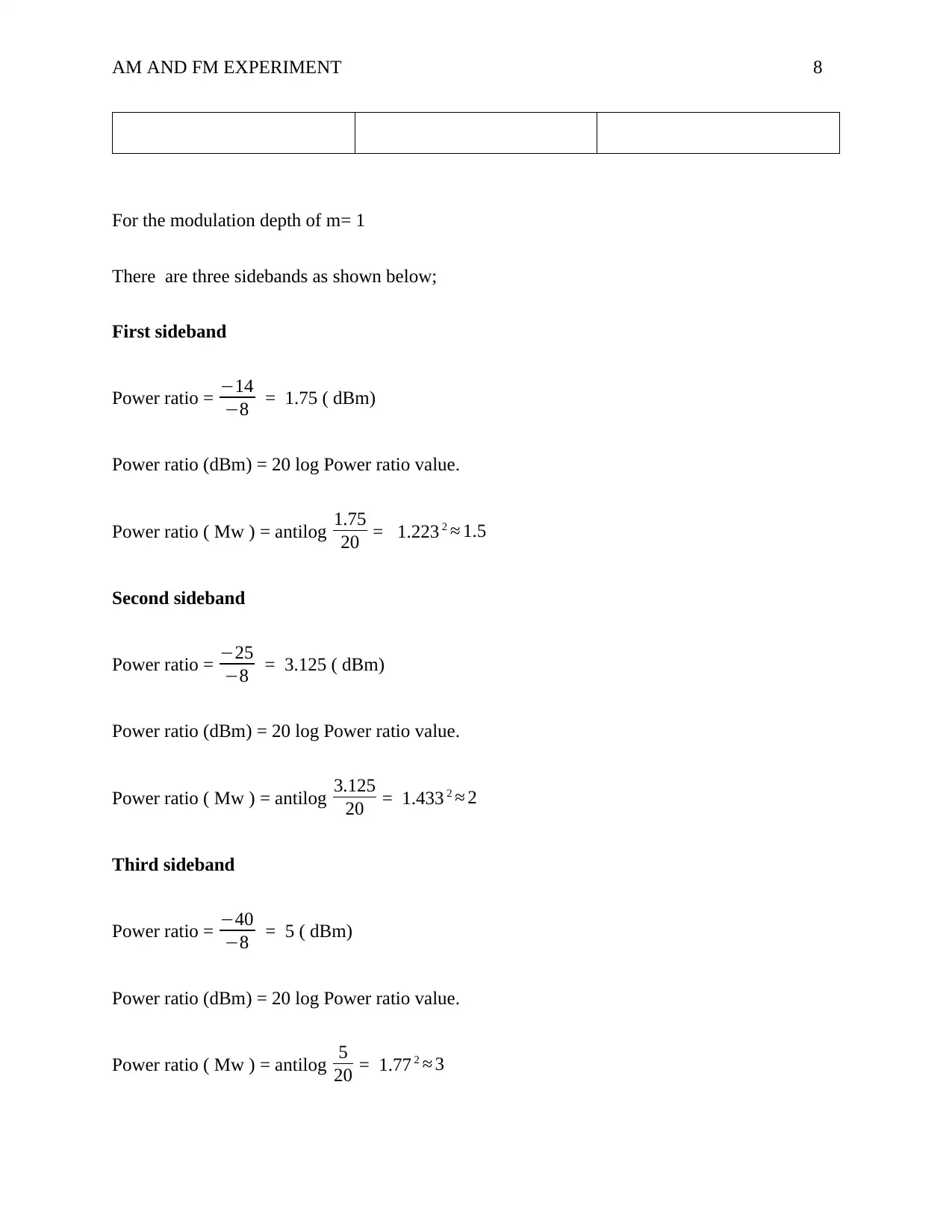
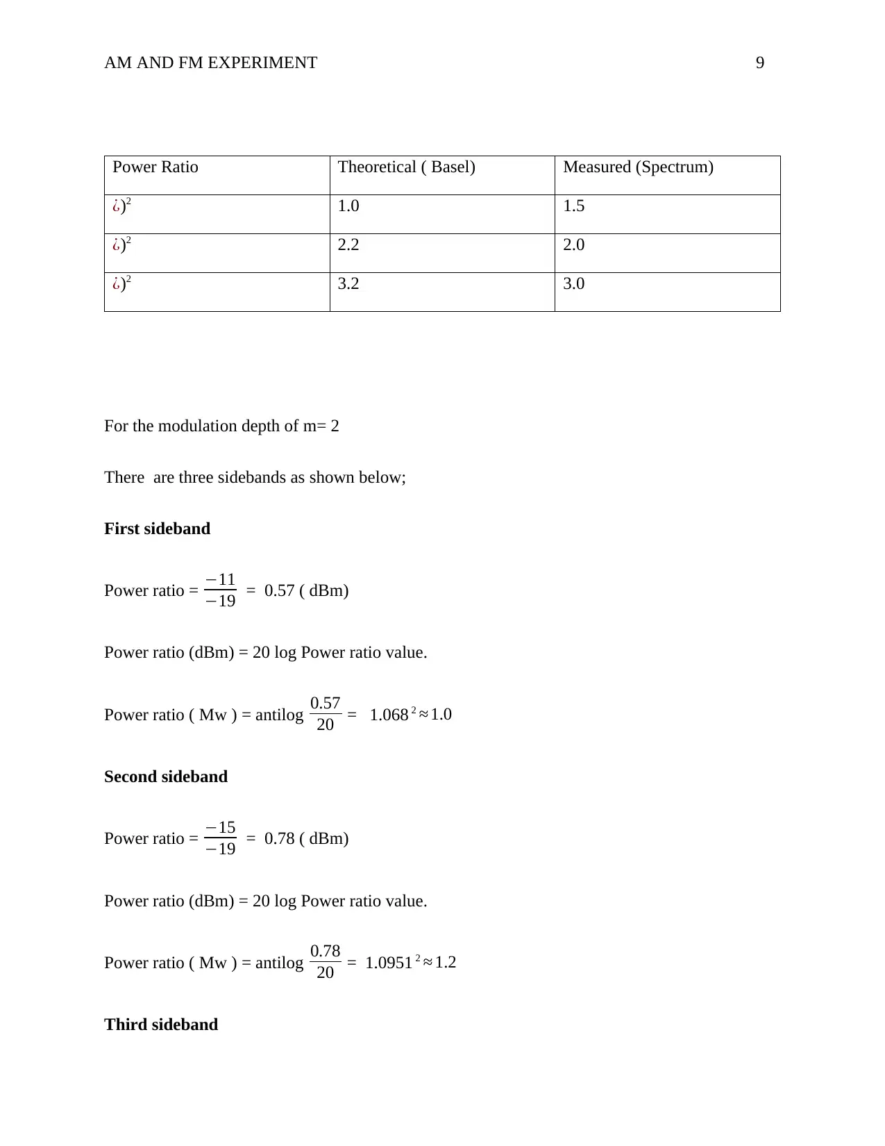
For the modulation depth of m= 1
There are three sidebands as shown below;
First sideband
Power ratio = −14
−8 = 1.75 ( dBm)
Power ratio (dBm) = 20 log Power ratio value.
Power ratio ( Mw ) = antilog 1.75
20 = 1.223 2 ≈ 1.5
Second sideband
Power ratio = −25
−8 = 3.125 ( dBm)
Power ratio (dBm) = 20 log Power ratio value.
Power ratio ( Mw ) = antilog 3.125
20 = 1.433 2 ≈ 2
Third sideband
Power ratio = −40
−8 = 5 ( dBm)
Power ratio (dBm) = 20 log Power ratio value.
Power ratio ( Mw ) = antilog 5
20 = 1.77 2 ≈ 3
AM AND FM EXPERIMENT 9
Power Ratio Theoretical ( Basel) Measured (Spectrum)
¿)2 1.0 1.5
¿)2 2.2 2.0
¿)2 3.2 3.0
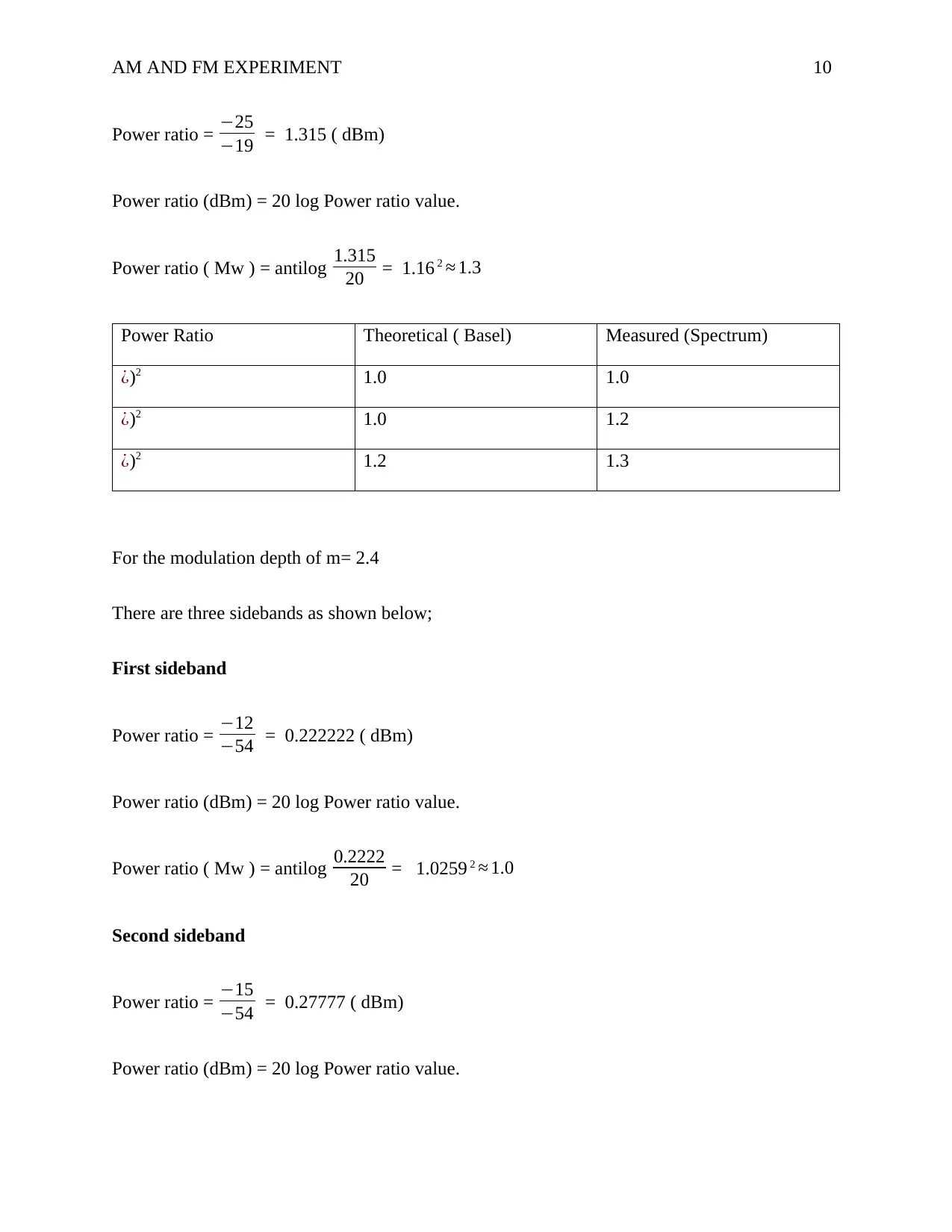
For the modulation depth of m= 2
There are three sidebands as shown below;
First sideband
Power ratio = −11
−19 = 0.57 ( dBm)
Power ratio (dBm) = 20 log Power ratio value.
Power ratio ( Mw ) = antilog 0.57
20 = 1.068 2 ≈ 1.0
Second sideband
Power ratio = −15
−19 = 0.78 ( dBm)
Power ratio (dBm) = 20 log Power ratio value.
Power ratio ( Mw ) = antilog 0.78
20 = 1.0951 2 ≈ 1.2
Third sideband
⊘ This is a preview!⊘
Do you want full access?
Subscribe today to unlock all pages.

Trusted by 1+ million students worldwide
AM AND FM EXPERIMENT 10
Power ratio = −25
−19 = 1.315 ( dBm)
Power ratio (dBm) = 20 log Power ratio value.
Power ratio ( Mw ) = antilog 1.315
20 = 1.16 2 ≈ 1.3
Power Ratio Theoretical ( Basel) Measured (Spectrum)
¿)2 1.0 1.0
¿)2 1.0 1.2
¿)2 1.2 1.3
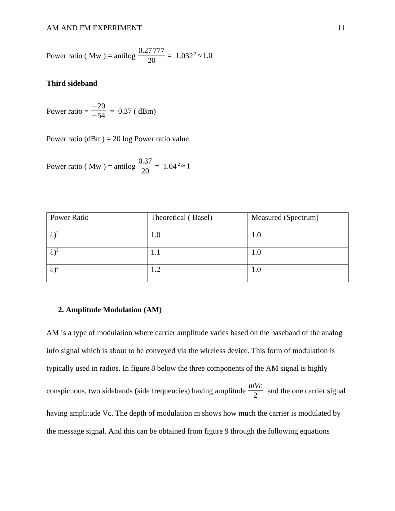
For the modulation depth of m= 2.4
There are three sidebands as shown below;
First sideband
Power ratio = −12
−54 = 0.222222 ( dBm)
Power ratio (dBm) = 20 log Power ratio value.
Power ratio ( Mw ) = antilog 0.2222
20 = 1.0259 2 ≈ 1.0
Second sideband
Power ratio = −15
−54 = 0.27777 ( dBm)
Power ratio (dBm) = 20 log Power ratio value.
Paraphrase This Document
Need a fresh take? Get an instant paraphrase of this document with our AI Paraphraser
AM AND FM EXPERIMENT 11
Power ratio ( Mw ) = antilog 0.27 777
20 = 1.032 2 ≈ 1.0
Third sideband
Power ratio = −20
−54 = 0.37 ( dBm)
Power ratio (dBm) = 20 log Power ratio value.
Power ratio ( Mw ) = antilog 0.37
20 = 1.04 2 ≈ 1
Power Ratio Theoretical ( Basel) Measured (Spectrum)
¿)2 1.0 1.0
¿)2 1.1 1.0
¿)2 1.2 1.0
2. Amplitude Modulation (AM)
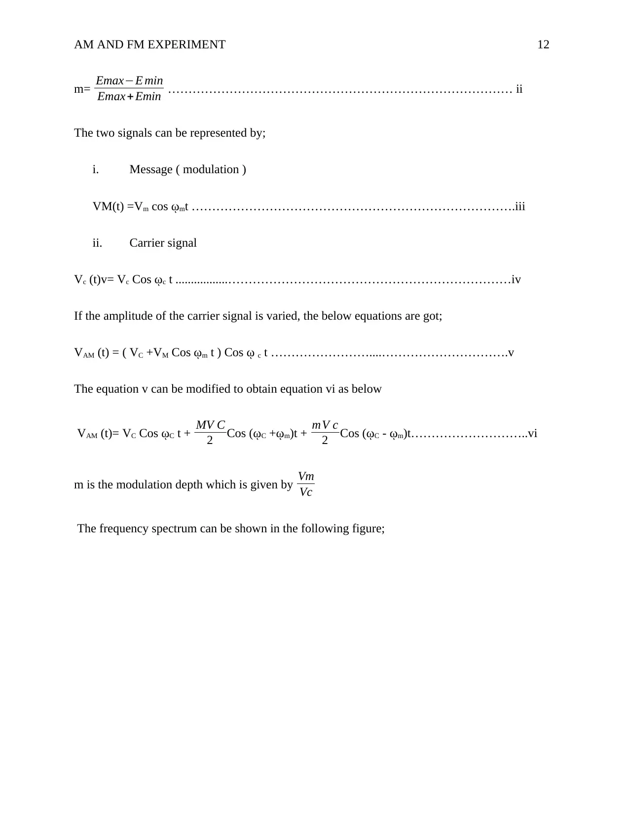
AM is a type of modulation where carrier amplitude varies based on the baseband of the analog
info signal which is about to be conveyed via the wireless device. This form of modulation is
typically used in radios. In figure 8 below the three components of the AM signal is highly
conspicuous, two sidebands (side frequencies) having amplitude mVc
2 and the one carrier signal
having amplitude Vc. The depth of modulation m shows how much the carrier is modulated by
the message signal. And this can be obtained from figure 9 through the following equations
AM AND FM EXPERIMENT 12
m= Emax−E min
Emax + Emin ………………………………………………………………………… ii
The two signals can be represented by;
i. Message ( modulation )
VM(t) =Vm cos ῳmt …………………………………………………………………….iii
ii. Carrier signal
Vc (t)v= Vc Cos ῳc t .................……………………………………………………………iv
If the amplitude of the carrier signal is varied, the below equations are got;
VAM (t) = ( VC +VM Cos ῳm t ) Cos ῳ c t ……………………....………………………….v
The equation v can be modified to obtain equation vi as below
VAM (t)= VC Cos ῳC t + MV C
2 Cos (ῳC +ῳm)t + mV c
2 Cos (ῳC - ῳm)t………………………..vi
m is the modulation depth which is given by Vm
Vc
The frequency spectrum can be shown in the following figure;
⊘ This is a preview!⊘
Do you want full access?
Subscribe today to unlock all pages.

Trusted by 1+ million students worldwide
1 out of 18
Related Documents
Your All-in-One AI-Powered Toolkit for Academic Success.
+13062052269
info@desklib.com
Available 24*7 on WhatsApp / Email
![[object Object]](/_next/static/media/star-bottom.7253800d.svg)
Unlock your academic potential
Copyright © 2020–2025 A2Z Services. All Rights Reserved. Developed and managed by ZUCOL.


