Web and Database Concepts: System Design and Diagrams - Assessment 1
VerifiedAdded on 2022/12/15
|19
|1755
|51
Report
AI Summary
This report provides a comprehensive overview of web and database concepts, focusing on system design techniques and various diagrams. It begins with an introduction to database management systems and data analysis, emphasizing their importance in modern organizations. The main body delves into system design techniques such as structure charts, data flow-oriented design, data structure-oriented design, and object-oriented design, explaining their methodologies and applications. The report then explores the use of Entity Relationship Diagrams (ERD), Use Case diagrams, Activity Diagrams, Sequence Diagrams, and Class Diagrams in the context of an online catering services system, providing visual representations and explanations of each. The conclusion reinforces the significance of these concepts for efficient business management, especially with the advancement of technology. References to relevant books and journals are also included.
Introduction to Web
and Database Concepts
Assessment 1
and Database Concepts
Assessment 1
Paraphrase This Document
Need a fresh take? Get an instant paraphrase of this document with our AI Paraphraser
Table of Contents
INTRODUCTION...........................................................................................................................1
MAIN BODY...................................................................................................................................1
System design techniques...........................................................................................................1
Entity Relationship Diagram.......................................................................................................6
Use Case diagram......................................................................................................................12
Activity Diagram.......................................................................................................................13
Sequence Diagram....................................................................................................................14
Class Diagram...........................................................................................................................15
CONCLUSION..............................................................................................................................16
References:.....................................................................................................................................17
INTRODUCTION
Database management system can be defined as the handling and managing the large or
small data or information in an organization in order to add, retrieve, modify and delete the
information, this is done so that functioning of an organization can be smooth in future (Zerkin
and Pritychenko, 2018). Data analysis through online systems is an easy manner to perform so
that convenient way can be pick out to examine the data and information for better future
considerations. The following discussions is made on the system design techniques, entity
relationship diagram, use case diagram, activity diagram, sequence diagram and class diagram in
context of the given case study with proper findings and conclusion in order to develop the
online catering services system to manage the customers and stakeholders in an effective and
efficient manner.
MAIN BODY
System design techniques
Structure charts
It is defined as the fundamental method of structured system design, it is considered as
the graphic representation of the modular hierarchy and the relationships among them
(Altenhoff, Glover, Train and Redestig, 2018). It is mainly of two types, structured charts and
program structured charts. Former one represents the brief breakdown of the functions of the
software without taking any consideration like package into account. Latter one depicts the
actual programs and processes which are to be build up or developed. Structure charts represents
the structure of the system. It is also can be used to showcase the information flow among
modules. It is not responsible for the illustration of the flow of control and more over it also not
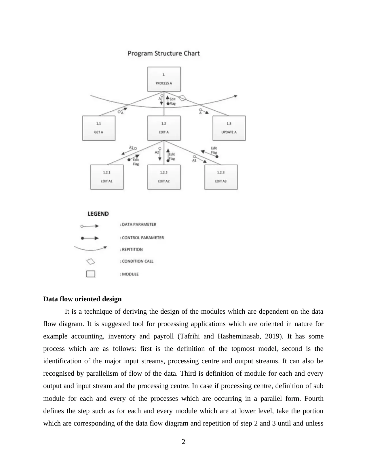
renders any information about the sequencing of events and condition tests. The below figure is
of the program structure chart which illustrates the assorted symbols that can be utilised. A box
depicts the module, lines which are connecting the modules are representing the calling
hierarchy. Parameters, conditional calls and loops are also can be illustrated on the structured
charts as well by using the symbols shown.
1
⊘ This is a preview!⊘
Do you want full access?
Subscribe today to unlock all pages.

Trusted by 1+ million students worldwide
Data flow oriented design
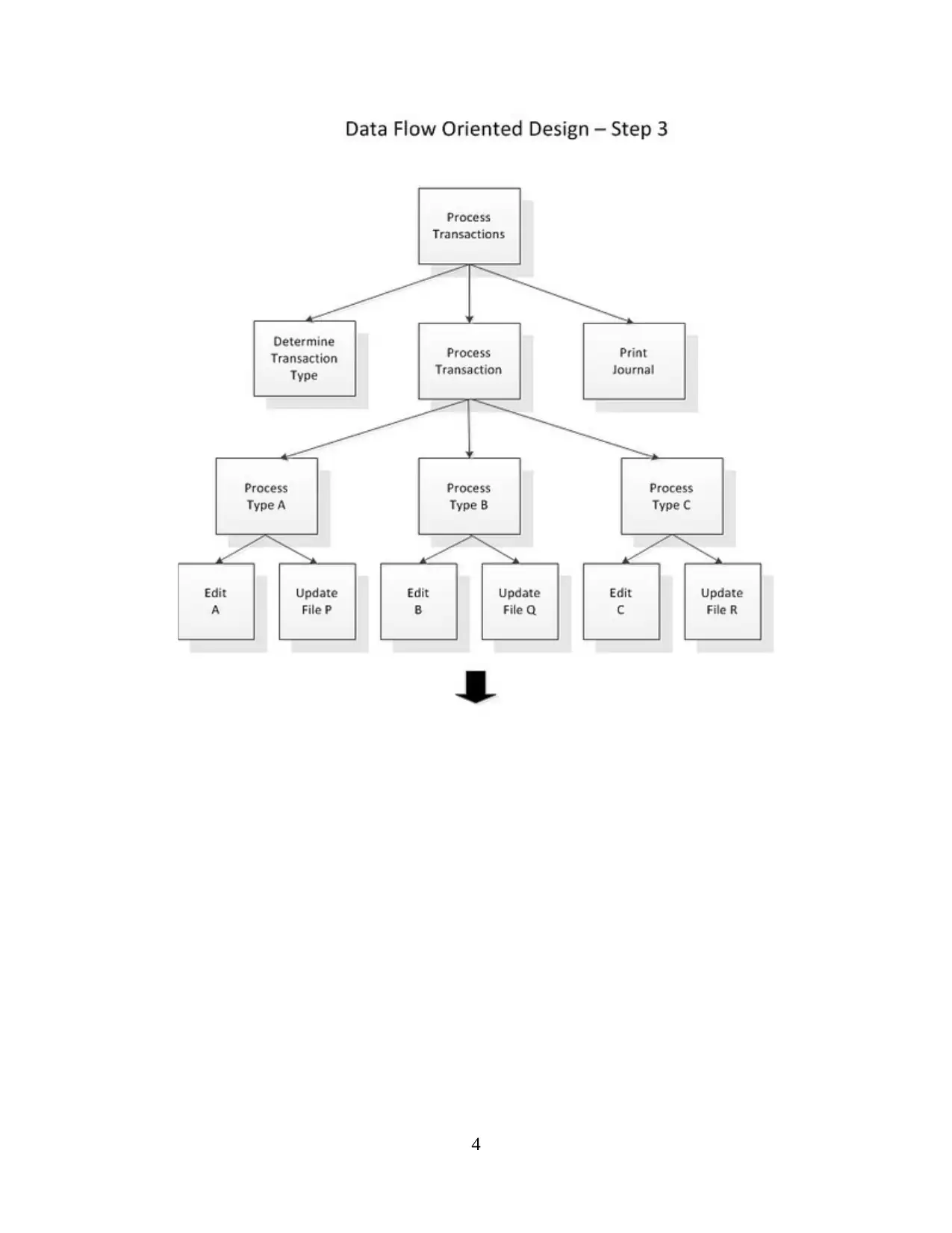
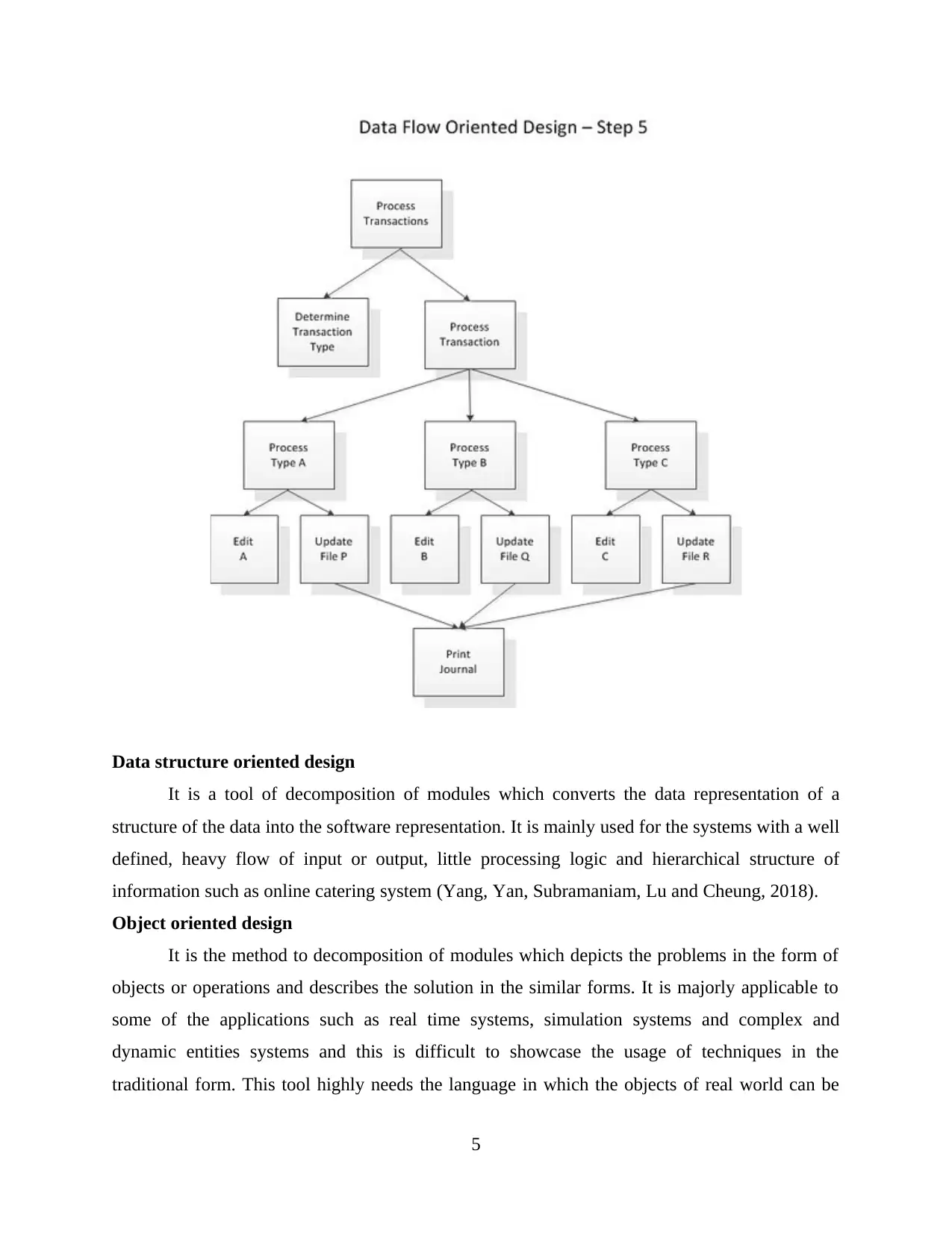
It is a technique of deriving the design of the modules which are dependent on the data
flow diagram. It is suggested tool for processing applications which are oriented in nature for
example accounting, inventory and payroll (Tafrihi and Hasheminasab, 2019). It has some
process which are as follows: first is the definition of the topmost model, second is the
identification of the major input streams, processing centre and output streams. It can also be
recognised by parallelism of flow of the data. Third is definition of module for each and every
output and input stream and the processing centre. In case if processing centre, definition of sub
module for each and every of the processes which are occurring in a parallel form. Fourth
defines the step such as for each and every module which are at lower level, take the portion
which are corresponding of the data flow diagram and repetition of step 2 and 3 until and unless
2
Paraphrase This Document
Need a fresh take? Get an instant paraphrase of this document with our AI Paraphraser
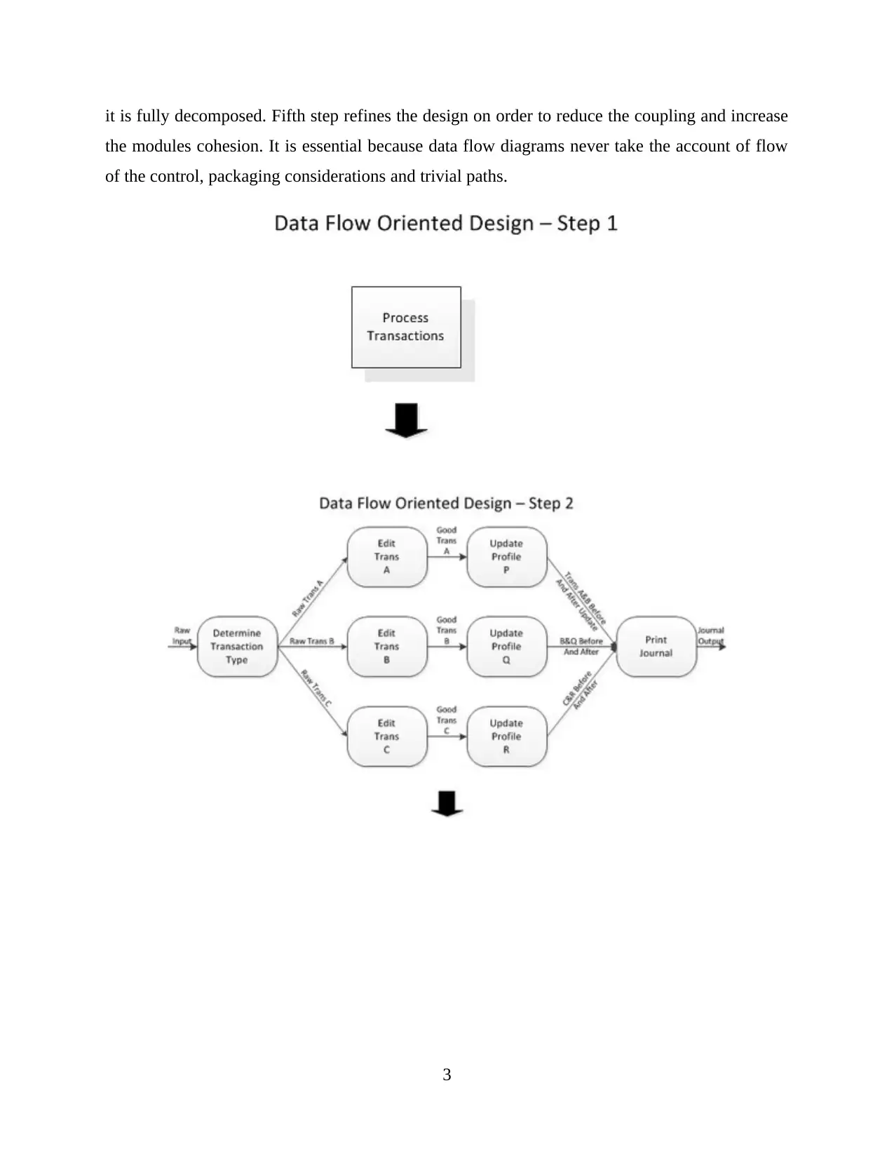
it is fully decomposed. Fifth step refines the design on order to reduce the coupling and increase
the modules cohesion. It is essential because data flow diagrams never take the account of flow
of the control, packaging considerations and trivial paths.
3
the modules cohesion. It is essential because data flow diagrams never take the account of flow
of the control, packaging considerations and trivial paths.
3
4
⊘ This is a preview!⊘
Do you want full access?
Subscribe today to unlock all pages.

Trusted by 1+ million students worldwide
Data structure oriented design
It is a tool of decomposition of modules which converts the data representation of a
structure of the data into the software representation. It is mainly used for the systems with a well
defined, heavy flow of input or output, little processing logic and hierarchical structure of
information such as online catering system (Yang, Yan, Subramaniam, Lu and Cheung, 2018).
Object oriented design
It is the method to decomposition of modules which depicts the problems in the form of
objects or operations and describes the solution in the similar forms. It is majorly applicable to
some of the applications such as real time systems, simulation systems and complex and
dynamic entities systems and this is difficult to showcase the usage of techniques in the
traditional form. This tool highly needs the language in which the objects of real world can be
5
Paraphrase This Document
Need a fresh take? Get an instant paraphrase of this document with our AI Paraphraser
illustrated, such languages typically develop the classes of an object in a particular application
(Majeed and Rauf, 2018). For each and every class, the properties and attributes in each and
every object in the class share are described. The activity with each and every object cab execute
are defined. Such things are written in the terms of messages to which each and every object in
the class can be able to respond. It is resulted that all communication among any two of the
objects even when are they from the different classes or not is executed by sending the messages.
Therefore, object oriented languages are containing the high degree of encapsulation feature in
them in which each and every object is accountable for their own operations and not an another
object can have a access on their structure in a direct way. Hence, the total result is that each and
every messages is similar to the separate black box, which is a property which formulates the
designing of the system in a more manageable manner.
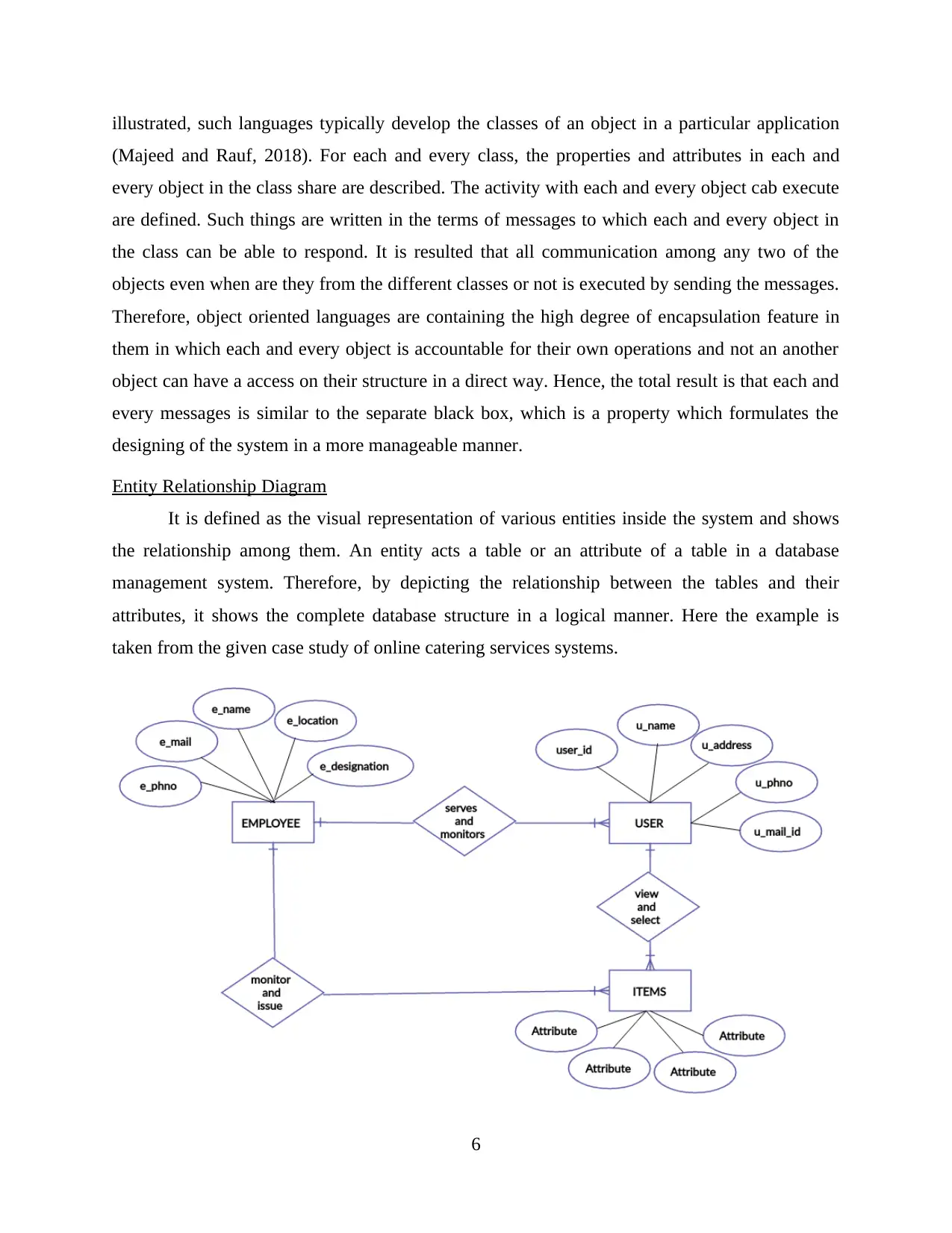
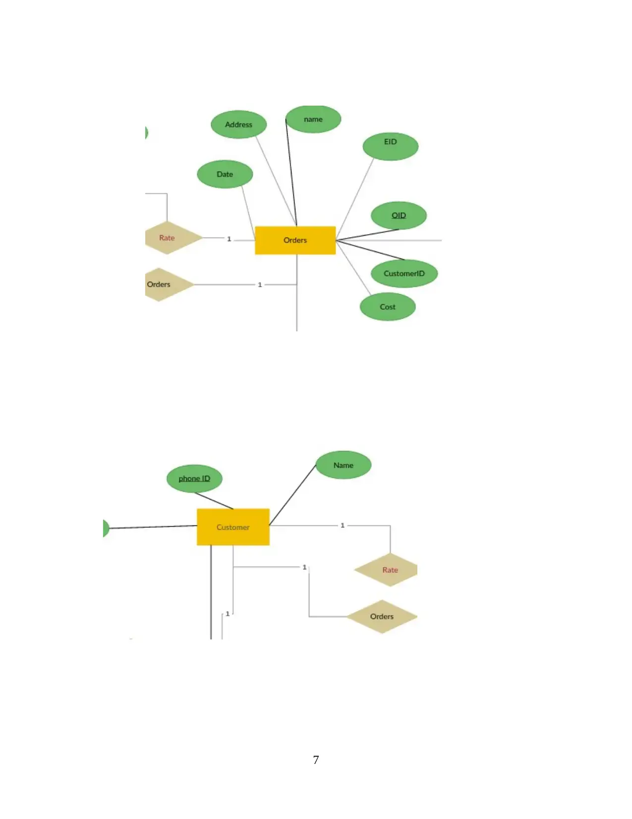
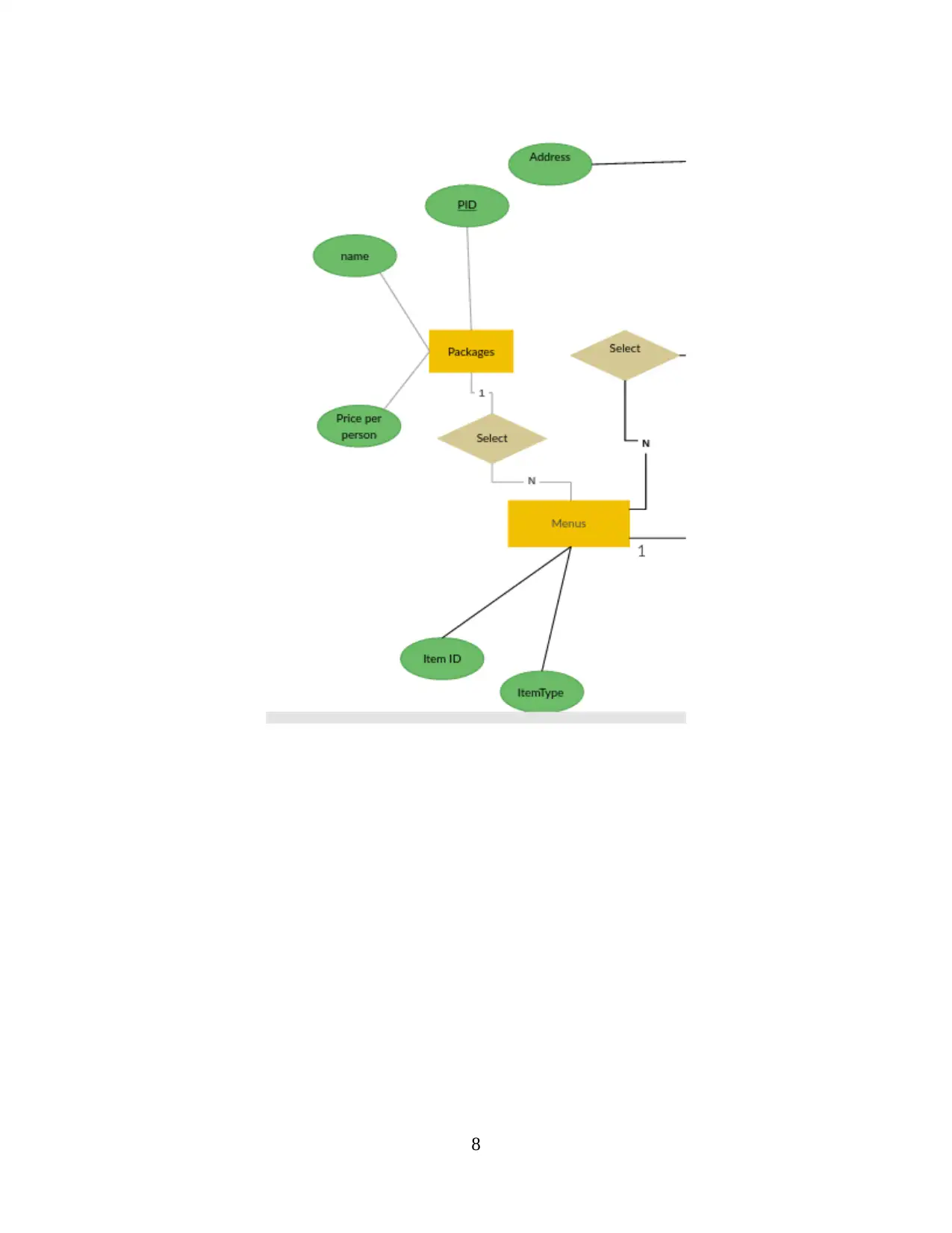
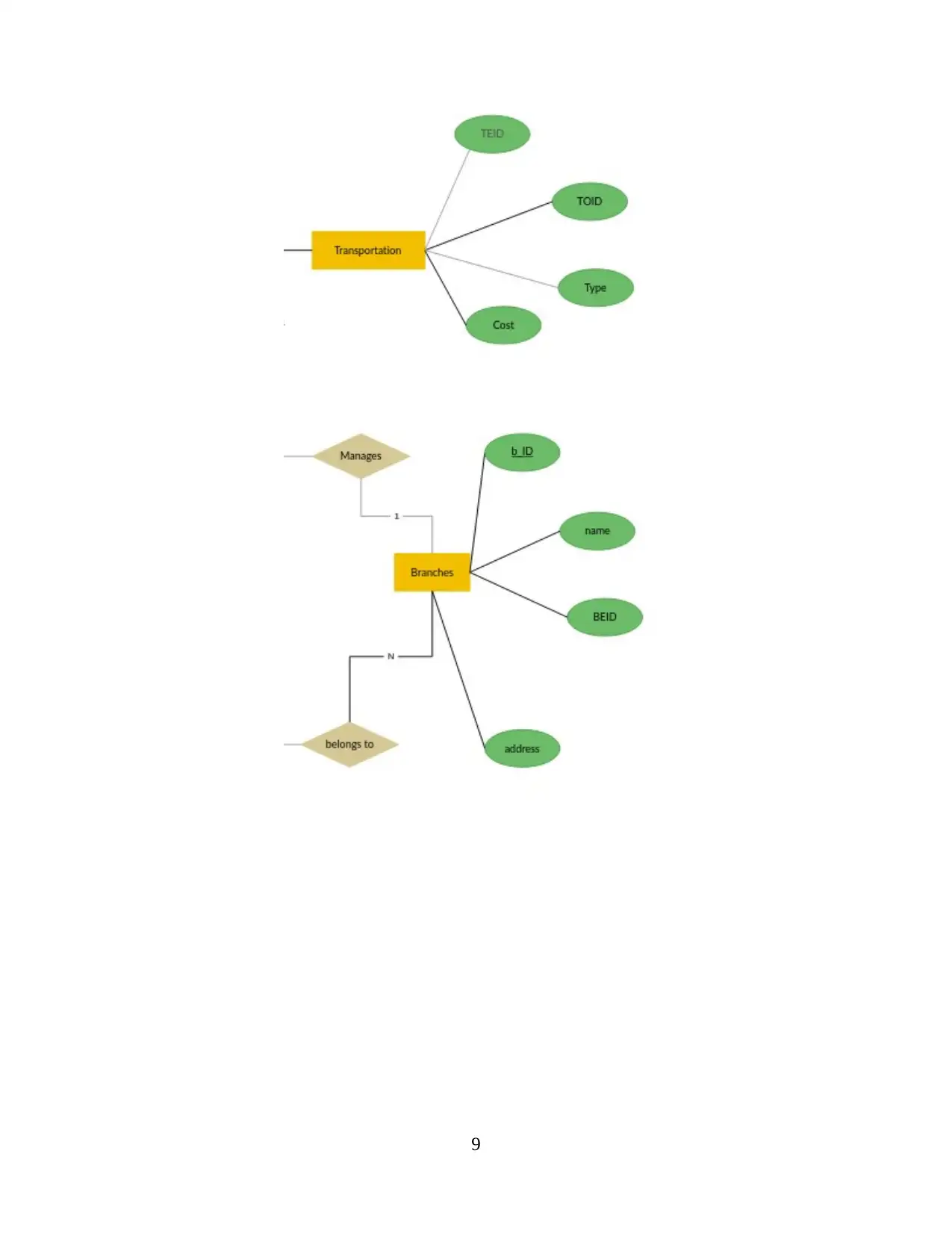
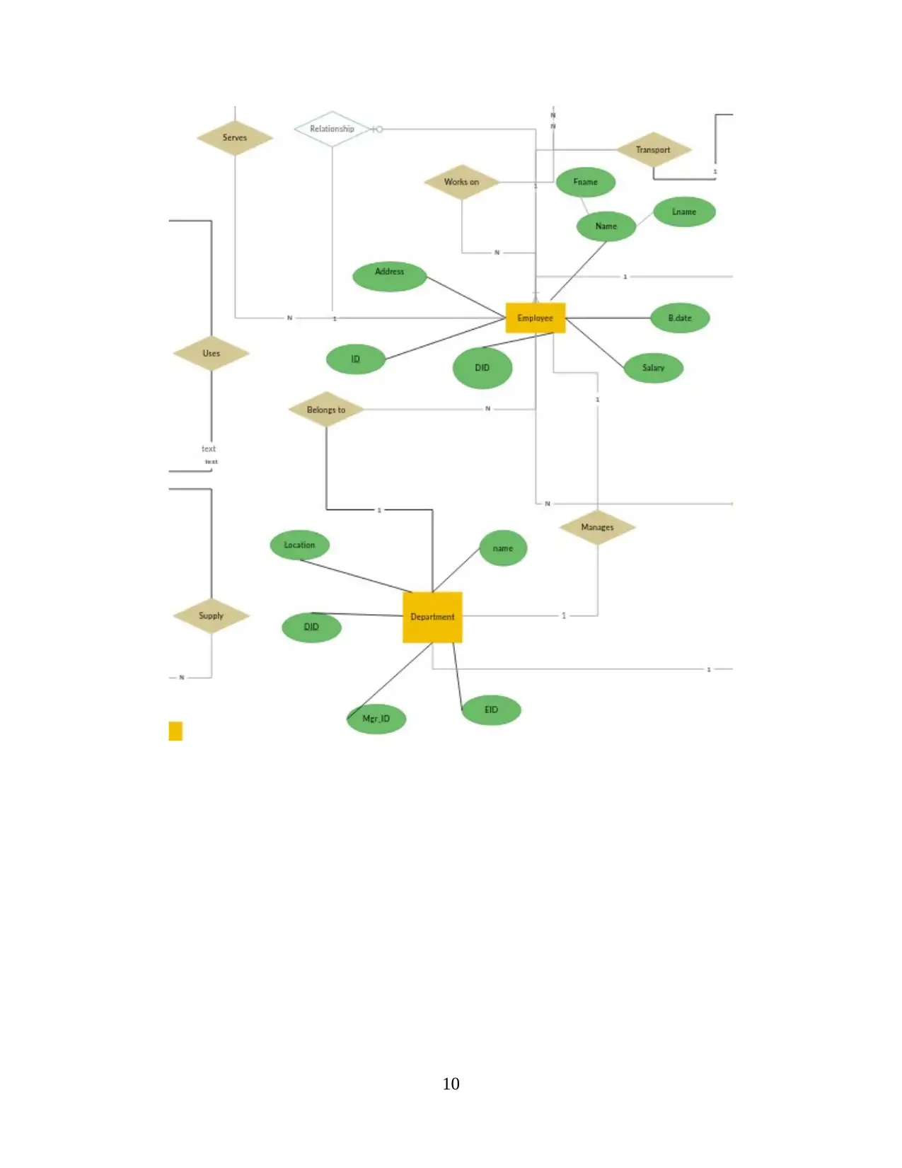
Entity Relationship Diagram
It is defined as the visual representation of various entities inside the system and shows
the relationship among them. An entity acts a table or an attribute of a table in a database
management system. Therefore, by depicting the relationship between the tables and their
attributes, it shows the complete database structure in a logical manner. Here the example is
taken from the given case study of online catering services systems.
6
7
⊘ This is a preview!⊘
Do you want full access?
Subscribe today to unlock all pages.

Trusted by 1+ million students worldwide
8
Paraphrase This Document
Need a fresh take? Get an instant paraphrase of this document with our AI Paraphraser
9
10
⊘ This is a preview!⊘
Do you want full access?
Subscribe today to unlock all pages.

Trusted by 1+ million students worldwide
1 out of 19
Related Documents
Your All-in-One AI-Powered Toolkit for Academic Success.
+13062052269
info@desklib.com
Available 24*7 on WhatsApp / Email
![[object Object]](/_next/static/media/star-bottom.7253800d.svg)
Unlock your academic potential
Copyright © 2020–2025 A2Z Services. All Rights Reserved. Developed and managed by ZUCOL.


