Local Area Network Technologies: Design, Implementation & Analysis
VerifiedAdded on 2023/05/29
|26
|5223
|104
Report
AI Summary
This report provides a comprehensive solution to a Local Area Network (LAN) assignment, covering various aspects of LAN technologies, design, implementation, and management. It begins with a critical analysis of different network topologies, including Bus, Ring, Star, and Mesh, ultimately selecting Star topology for its robustness and suitability for the given scenario. The report details the design of a hierarchical network infrastructure using CISCO's Network Lab Simulator, incorporating 121 computers, 4 printers, and 4 servers, segmented into Finance, HR, Design, and Sales departments, each utilizing Star topology and VLAN configurations. The evaluation of network components and design is discussed, followed by the implementation steps and configuration of the network. Furthermore, the report explores tools for monitoring the LAN, strategies for enhancing its immunity from attacks, and methods for improving its overall performance, security, and reliability through hierarchical network design principles.

LOCAL AREA NETWORK
ASSIGNMENT
Student name:
Student ID:
ASSIGNMENT
Student name:
Student ID:
Paraphrase This Document
Need a fresh take? Get an instant paraphrase of this document with our AI Paraphraser
Table of Contents
Task 1 :Understand the impact of LAN technologies.....................................................................3
1.1 Critical Analysis among the Network Topologies for choosing the best for Design............3
1.2 Robustness of LAN................................................................................................................7
1.3 Imposing Hierarchical Network over LAN for Security, Reliability & Performance...........8
Task 2 :Be able to design LAN infrastructures.............................................................................10
2.1 Design network infrastructure to fulfill the requirement of above scenario........................10
2.2 Evaluation of network components and design...................................................................13
Task 3 :Be able to implement LAN infrastructures.......................................................................16
3.1. Build and configure the entire network...............................................................................16
Task 4 :Be able to manage LAN infrastructures...........................................................................23
4.1 Tools to Monitor LAN.........................................................................................................23
4.2 Immunity of LAN from attack.............................................................................................23
4.3 Improvement of LAN...........................................................................................................24
References......................................................................................................................................25
2
Task 1 :Understand the impact of LAN technologies
1.1 Critical Analysis among the Network Topologies for choosing the best for Design
In a large building, or in a business area or in an office, all the systems are connected using Local
Area Network or LAN. In this section we will discuss about the analysis of the existing network
topologies with their sound attributes. After analysis is done, we will consider the particular
topology to be suitable for our design.
Bus Topology
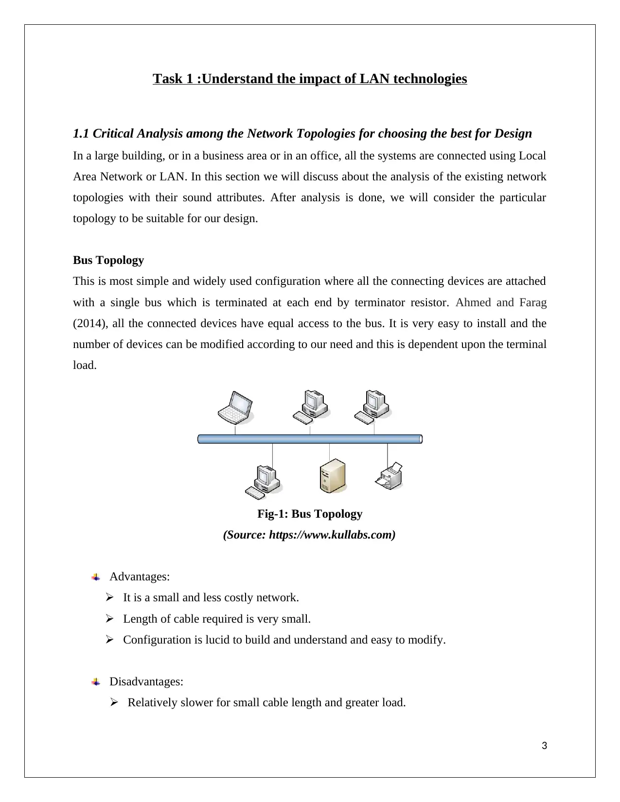
This is most simple and widely used configuration where all the connecting devices are attached
with a single bus which is terminated at each end by terminator resistor. Ahmed and Farag
(2014), all the connected devices have equal access to the bus. It is very easy to install and the
number of devices can be modified according to our need and this is dependent upon the terminal
load.
Fig-1: Bus Topology
(Source: https://www.kullabs.com)
Advantages:
It is a small and less costly network.
Length of cable required is very small.
Configuration is lucid to build and understand and easy to modify.
Disadvantages:
Relatively slower for small cable length and greater load.
3
⊘ This is a preview!⊘
Do you want full access?
Subscribe today to unlock all pages.

Trusted by 1+ million students worldwide
If any part of the cable creates any problem for data transmission, the whole system
faces the similar problem.
Ring Topology
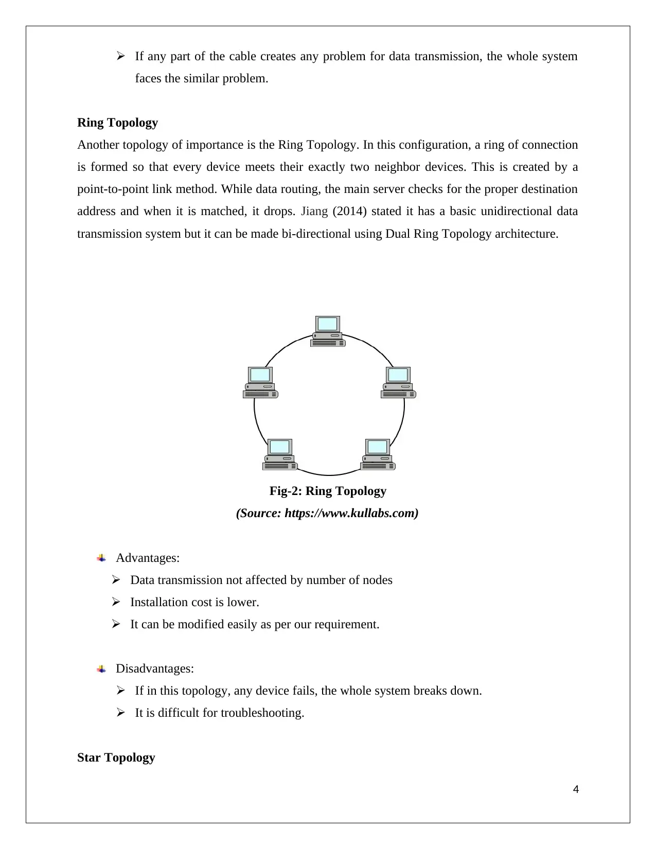
Another topology of importance is the Ring Topology. In this configuration, a ring of connection
is formed so that every device meets their exactly two neighbor devices. This is created by a
point-to-point link method. While data routing, the main server checks for the proper destination
address and when it is matched, it drops. Jiang (2014) stated it has a basic unidirectional data
transmission system but it can be made bi-directional using Dual Ring Topology architecture.
Fig-2: Ring Topology
(Source: https://www.kullabs.com)
Advantages:
Data transmission not affected by number of nodes
Installation cost is lower.
It can be modified easily as per our requirement.
Disadvantages:
If in this topology, any device fails, the whole system breaks down.
It is difficult for troubleshooting.
Star Topology
4
Paraphrase This Document
Need a fresh take? Get an instant paraphrase of this document with our AI Paraphraser
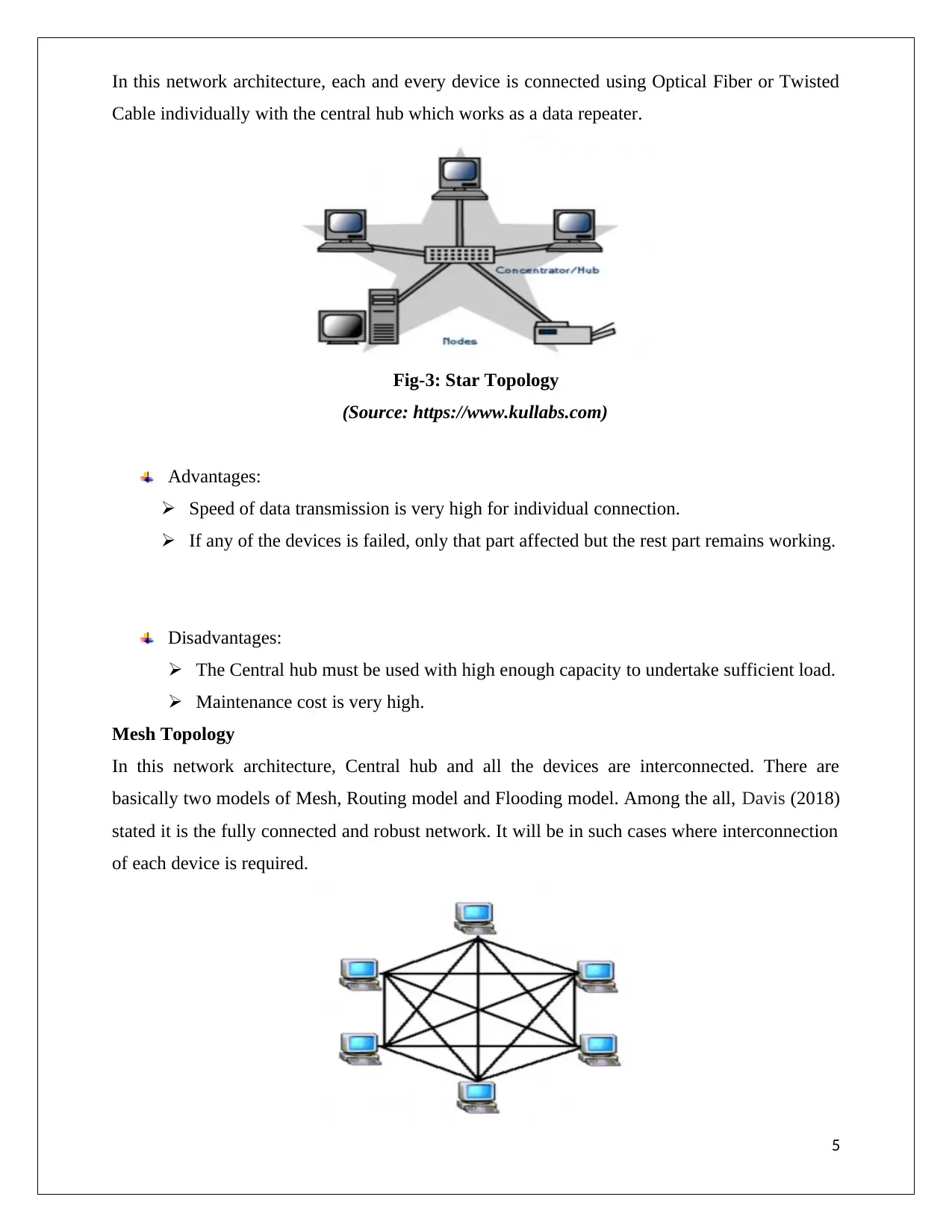
In this network architecture, each and every device is connected using Optical Fiber or Twisted
Cable individually with the central hub which works as a data repeater.
Fig-3: Star Topology
(Source: https://www.kullabs.com)
Advantages:
Speed of data transmission is very high for individual connection.
If any of the devices is failed, only that part affected but the rest part remains working.
Disadvantages:
The Central hub must be used with high enough capacity to undertake sufficient load.
Maintenance cost is very high.
Mesh Topology
In this network architecture, Central hub and all the devices are interconnected. There are
basically two models of Mesh, Routing model and Flooding model. Among the all, Davis (2018)
stated it is the fully connected and robust network. It will be in such cases where interconnection
of each device is required.
5
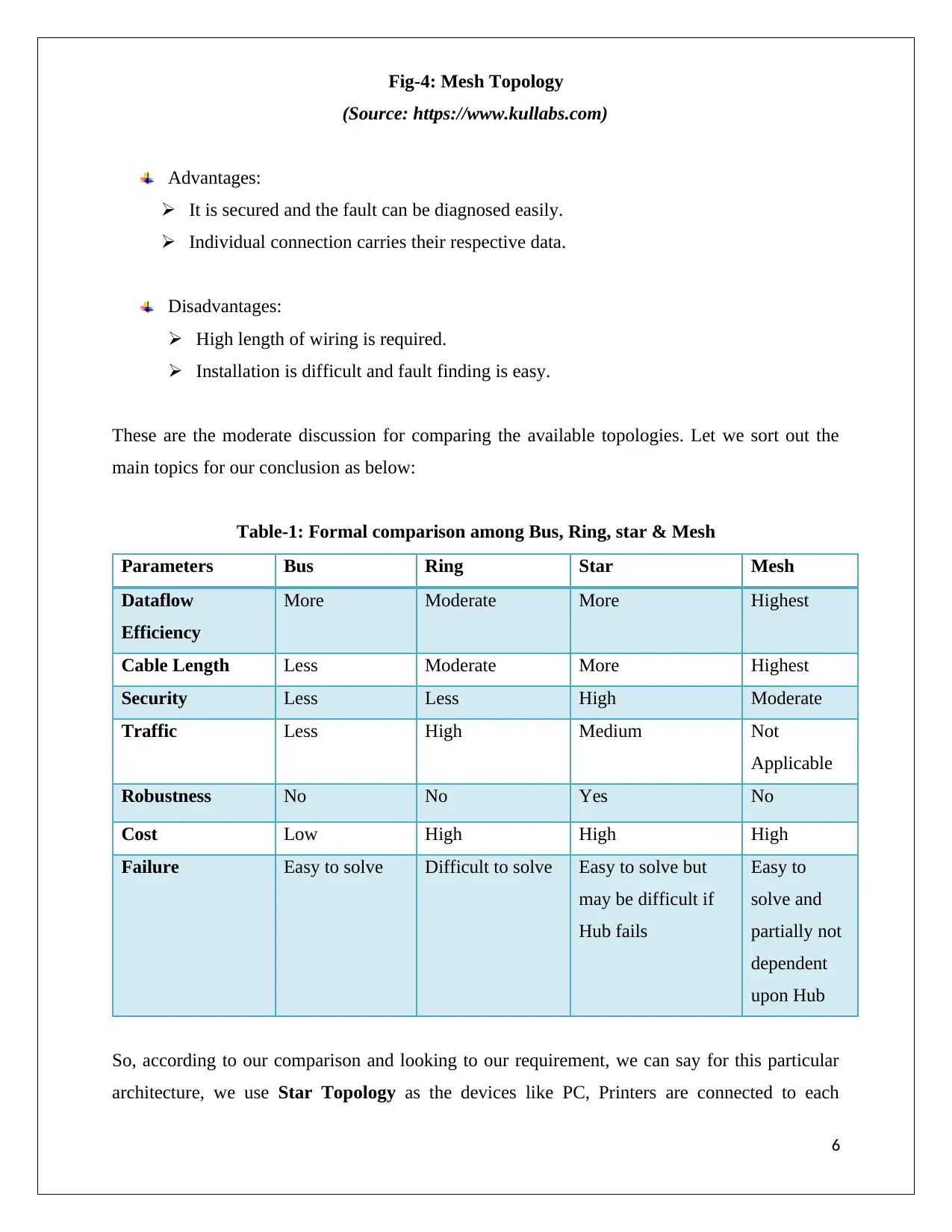
Fig-4: Mesh Topology
(Source: https://www.kullabs.com)
Advantages:
It is secured and the fault can be diagnosed easily.
Individual connection carries their respective data.
Disadvantages:
High length of wiring is required.
Installation is difficult and fault finding is easy.
These are the moderate discussion for comparing the available topologies. Let we sort out the
main topics for our conclusion as below:
Table-1: Formal comparison among Bus, Ring, star & Mesh
Parameters Bus Ring Star Mesh
Dataflow
Efficiency
More Moderate More Highest
Cable Length Less Moderate More Highest
Security Less Less High Moderate
Traffic Less High Medium Not
Applicable
Robustness No No Yes No
Cost Low High High High
Failure Easy to solve Difficult to solve Easy to solve but
may be difficult if
Hub fails
Easy to
solve and
partially not
dependent
upon Hub
So, according to our comparison and looking to our requirement, we can say for this particular
architecture, we use Star Topology as the devices like PC, Printers are connected to each
6
⊘ This is a preview!⊘
Do you want full access?
Subscribe today to unlock all pages.

Trusted by 1+ million students worldwide
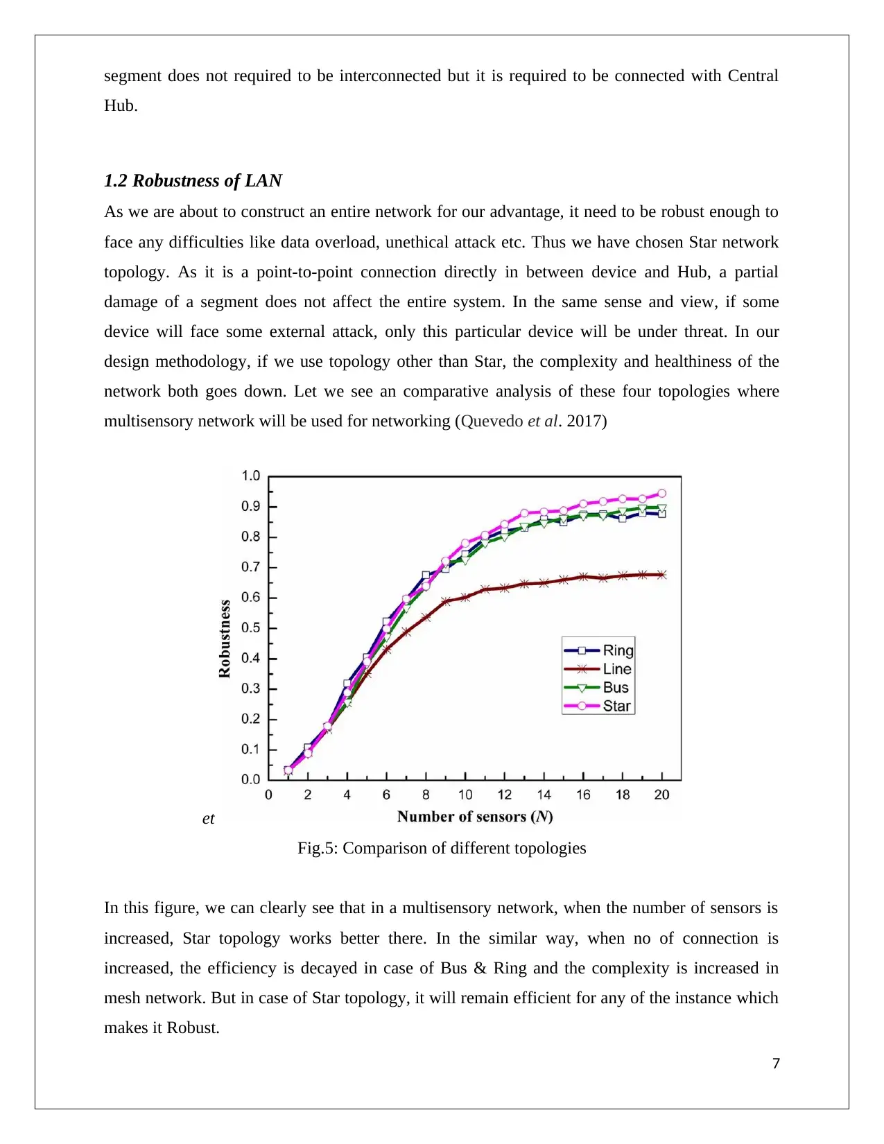
segment does not required to be interconnected but it is required to be connected with Central
Hub.
1.2 Robustness of LAN
As we are about to construct an entire network for our advantage, it need to be robust enough to
face any difficulties like data overload, unethical attack etc. Thus we have chosen Star network
topology. As it is a point-to-point connection directly in between device and Hub, a partial
damage of a segment does not affect the entire system. In the same sense and view, if some
device will face some external attack, only this particular device will be under threat. In our
design methodology, if we use topology other than Star, the complexity and healthiness of the
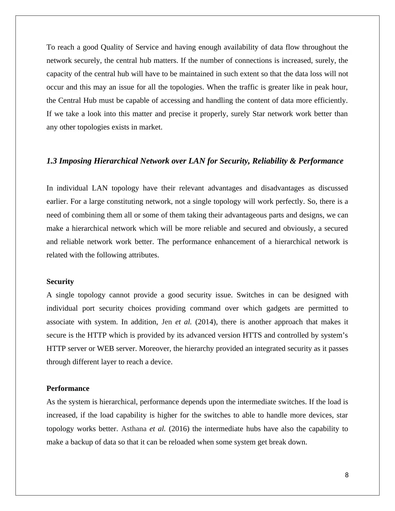
network both goes down. Let we see an comparative analysis of these four topologies where
multisensory network will be used for networking (Quevedo et al. 2017)
et
Fig.5: Comparison of different topologies
In this figure, we can clearly see that in a multisensory network, when the number of sensors is
increased, Star topology works better there. In the similar way, when no of connection is
increased, the efficiency is decayed in case of Bus & Ring and the complexity is increased in
mesh network. But in case of Star topology, it will remain efficient for any of the instance which
makes it Robust.
7
Paraphrase This Document
Need a fresh take? Get an instant paraphrase of this document with our AI Paraphraser
To reach a good Quality of Service and having enough availability of data flow throughout the
network securely, the central hub matters. If the number of connections is increased, surely, the
capacity of the central hub will have to be maintained in such extent so that the data loss will not
occur and this may an issue for all the topologies. When the traffic is greater like in peak hour,
the Central Hub must be capable of accessing and handling the content of data more efficiently.
If we take a look into this matter and precise it properly, surely Star network work better than
any other topologies exists in market.
1.3 Imposing Hierarchical Network over LAN for Security, Reliability & Performance
In individual LAN topology have their relevant advantages and disadvantages as discussed
earlier. For a large constituting network, not a single topology will work perfectly. So, there is a
need of combining them all or some of them taking their advantageous parts and designs, we can
make a hierarchical network which will be more reliable and secured and obviously, a secured
and reliable network work better. The performance enhancement of a hierarchical network is
related with the following attributes.
Security
A single topology cannot provide a good security issue. Switches in can be designed with
individual port security choices providing command over which gadgets are permitted to
associate with system. In addition, Jen et al. (2014), there is another approach that makes it
secure is the HTTP which is provided by its advanced version HTTS and controlled by system’s
HTTP server or WEB server. Moreover, the hierarchy provided an integrated security as it passes
through different layer to reach a device.
Performance
As the system is hierarchical, performance depends upon the intermediate switches. If the load is
increased, if the load capability is higher for the switches to able to handle more devices, star
topology works better. Asthana et al. (2016) the intermediate hubs have also the capability to
make a backup of data so that it can be reloaded when some system get break down.
8

Reliability
Reliability is a very basic feature of hierarchical network. These configuration supports multi
layered data transmission. So, for each layer, Li et al. (2015) stated the data or packet is being
checked so that there is a reliable transmission of data routing may take place. For multi layer
data routing, each and every hub can store the report of the data transmission.
9
⊘ This is a preview!⊘
Do you want full access?
Subscribe today to unlock all pages.

Trusted by 1+ million students worldwide
Task 2 :Be able to design LAN infrastructures
2.1 Design network infrastructure to fulfill the requirement of above scenario
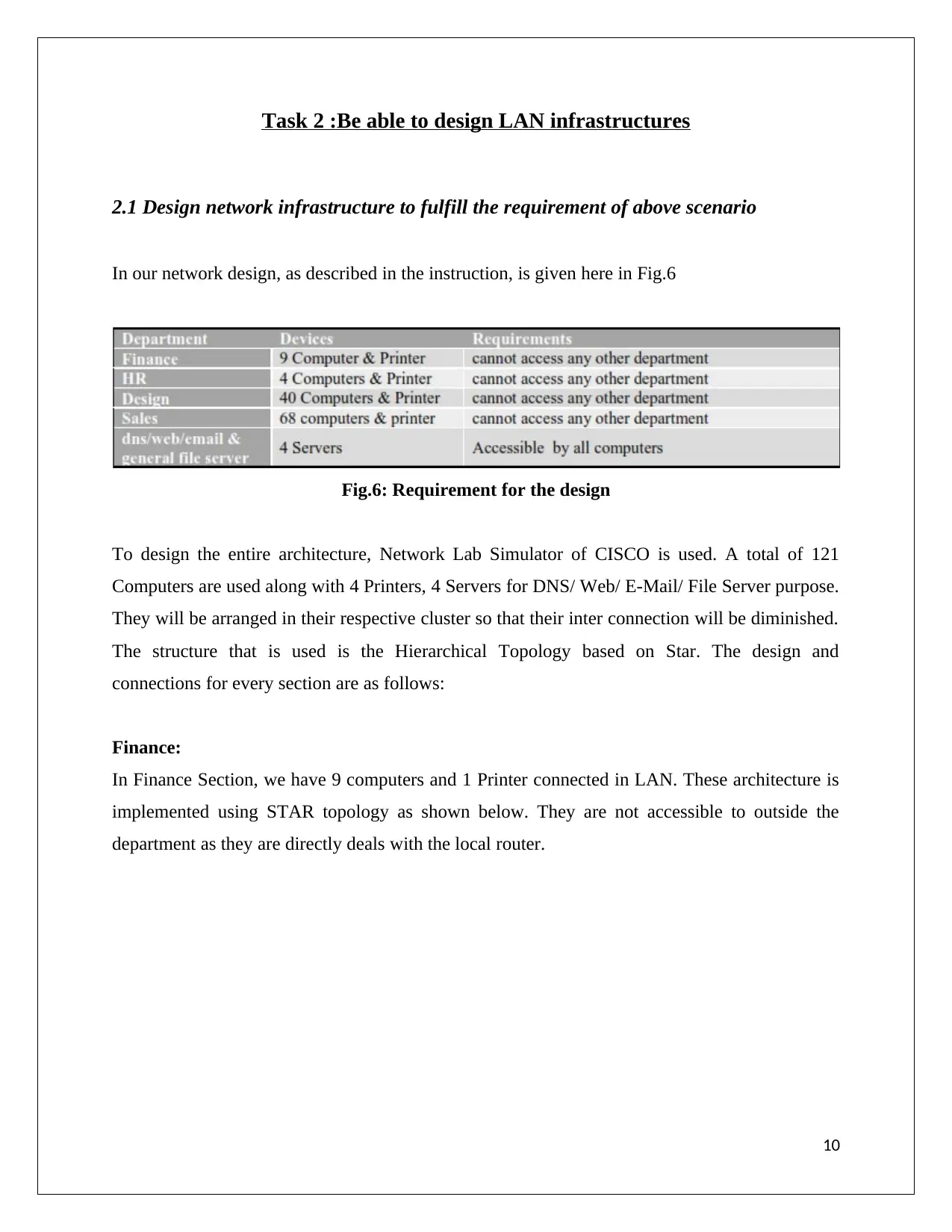
In our network design, as described in the instruction, is given here in Fig.6
Fig.6: Requirement for the design
To design the entire architecture, Network Lab Simulator of CISCO is used. A total of 121
Computers are used along with 4 Printers, 4 Servers for DNS/ Web/ E-Mail/ File Server purpose.
They will be arranged in their respective cluster so that their inter connection will be diminished.
The structure that is used is the Hierarchical Topology based on Star. The design and
connections for every section are as follows:
Finance:
In Finance Section, we have 9 computers and 1 Printer connected in LAN. These architecture is
implemented using STAR topology as shown below. They are not accessible to outside the
department as they are directly deals with the local router.
10
Paraphrase This Document
Need a fresh take? Get an instant paraphrase of this document with our AI Paraphraser
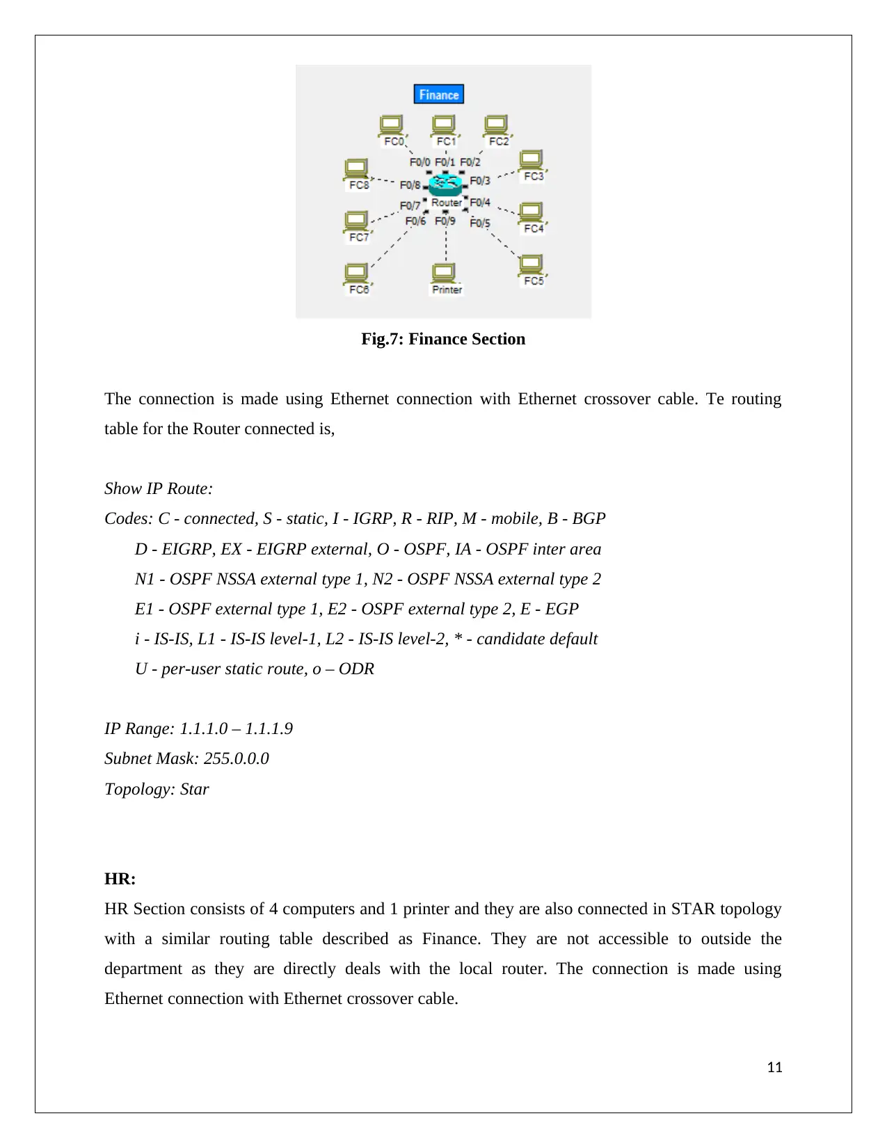
Fig.7: Finance Section
The connection is made using Ethernet connection with Ethernet crossover cable. Te routing
table for the Router connected is,
Show IP Route:
Codes: C - connected, S - static, I - IGRP, R - RIP, M - mobile, B - BGP
D - EIGRP, EX - EIGRP external, O - OSPF, IA - OSPF inter area
N1 - OSPF NSSA external type 1, N2 - OSPF NSSA external type 2
E1 - OSPF external type 1, E2 - OSPF external type 2, E - EGP
i - IS-IS, L1 - IS-IS level-1, L2 - IS-IS level-2, * - candidate default
U - per-user static route, o – ODR
IP Range: 1.1.1.0 – 1.1.1.9
Subnet Mask: 255.0.0.0
Topology: Star
HR:
HR Section consists of 4 computers and 1 printer and they are also connected in STAR topology
with a similar routing table described as Finance. They are not accessible to outside the
department as they are directly deals with the local router. The connection is made using
Ethernet connection with Ethernet crossover cable.
11
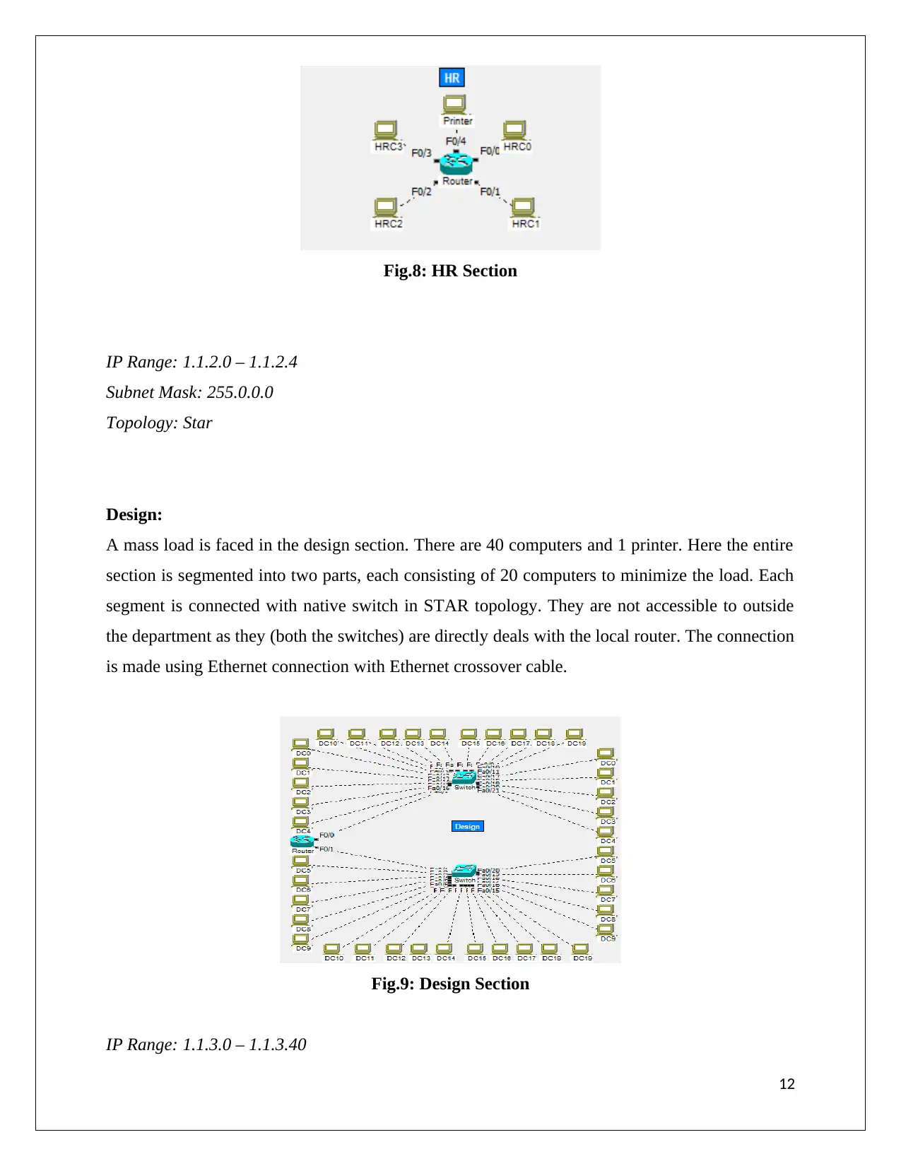
Fig.8: HR Section
IP Range: 1.1.2.0 – 1.1.2.4
Subnet Mask: 255.0.0.0
Topology: Star
Design:
A mass load is faced in the design section. There are 40 computers and 1 printer. Here the entire
section is segmented into two parts, each consisting of 20 computers to minimize the load. Each
segment is connected with native switch in STAR topology. They are not accessible to outside
the department as they (both the switches) are directly deals with the local router. The connection
is made using Ethernet connection with Ethernet crossover cable.
Fig.9: Design Section
IP Range: 1.1.3.0 – 1.1.3.40
12
⊘ This is a preview!⊘
Do you want full access?
Subscribe today to unlock all pages.

Trusted by 1+ million students worldwide
1 out of 26
Related Documents
Your All-in-One AI-Powered Toolkit for Academic Success.
+13062052269
info@desklib.com
Available 24*7 on WhatsApp / Email
![[object Object]](/_next/static/media/star-bottom.7253800d.svg)
Unlock your academic potential
Copyright © 2020–2025 A2Z Services. All Rights Reserved. Developed and managed by ZUCOL.


