Mechanical Engineering Principles: Case Study Analysis and Solutions
VerifiedAdded on 2023/05/30
|32
|1720
|335
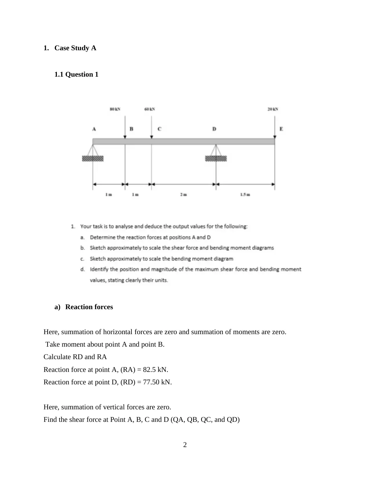
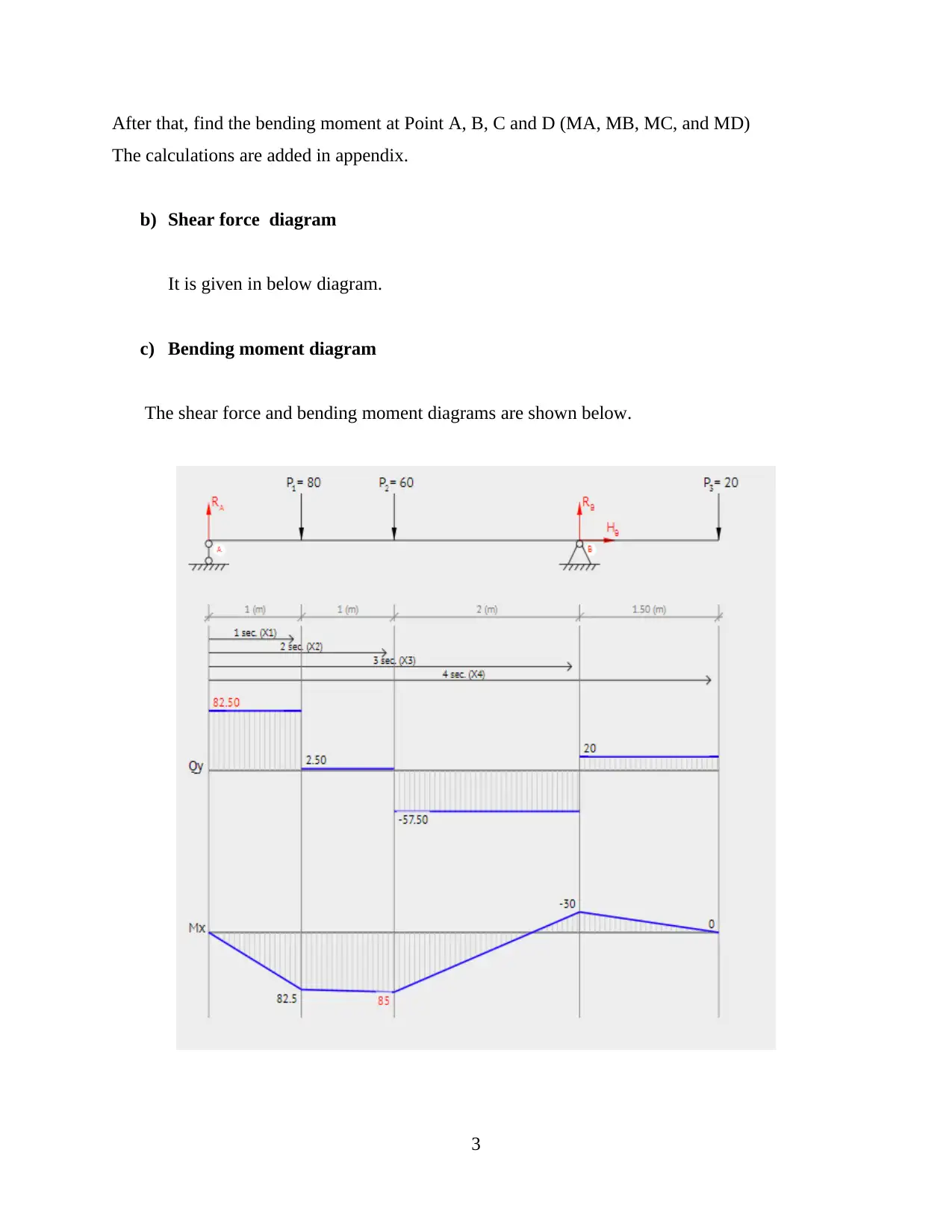
Case Study
AI Summary
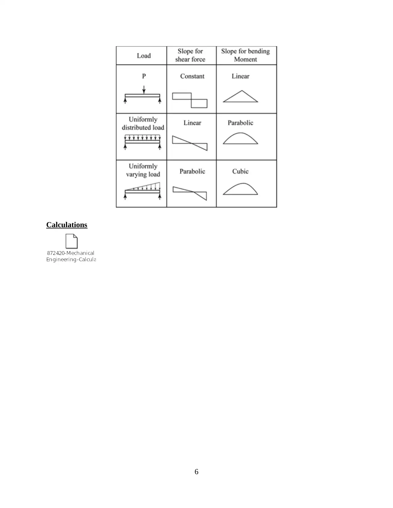
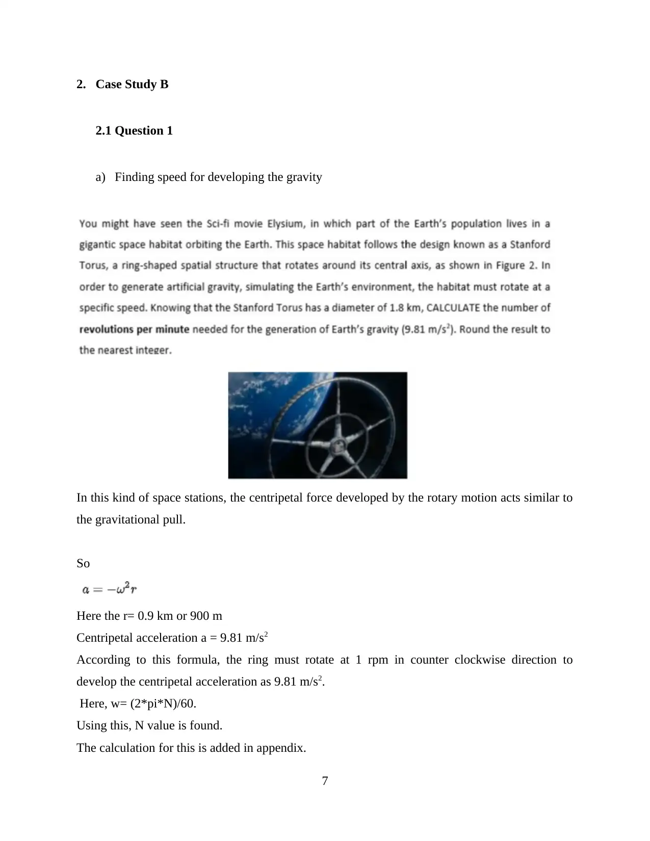
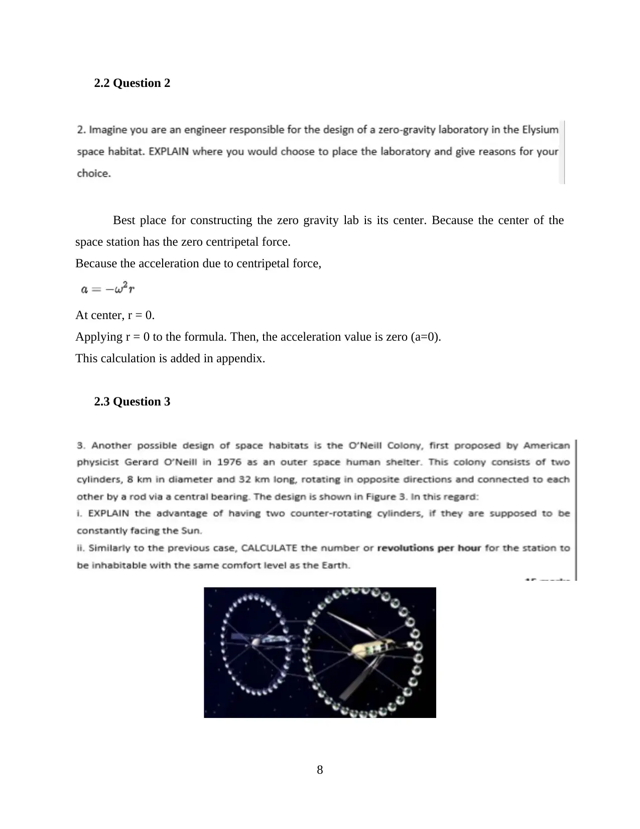
This document presents a comprehensive Mechanical Engineering case study, addressing various mechanical engineering principles through detailed analysis and solutions. The case study covers topics such as beam analysis, including the calculation of reaction forces, shear force diagrams, and bending moment diagrams. It delves into the properties of beams, different types of loadings, and beam classifications. Furthermore, the assignment explores concepts related to centripetal acceleration in space stations, the advantages of counter-rotating cylinders for sunlight harvesting, and calculations related to buoyancy forces and cargo capacity of barges. The document also examines pressure calculations at different depths and the need for ballast tanks in platform systems. Excel calculations are included to support the analysis. The assignment provides a practical application of mechanical engineering principles to solve real-world problems. This assignment is a valuable resource for students seeking to understand and apply mechanical engineering concepts.


1 out of 32
Related Documents


Your All-in-One AI-Powered Toolkit for Academic Success.
+13062052269
info@desklib.com
Available 24*7 on WhatsApp / Email
![[object Object]](/_next/static/media/star-bottom.7253800d.svg)
Copyright © 2020–2025 A2Z Services. All Rights Reserved. Developed and managed by ZUCOL.