logo

Bending Stress in Beam


Added on  2023-01-19

11 Pages1045 Words99 Views
Mechanics of materials 1
MECHANICS OF MATERIAL
Name of Student
Institution Affiliation
Bending Stress in Beam_1
Mechanics of materials 2
Title: BENDING STRESS IN BEAM
Objective
To avoid the normal stresses in a section of beam under bending
Theory
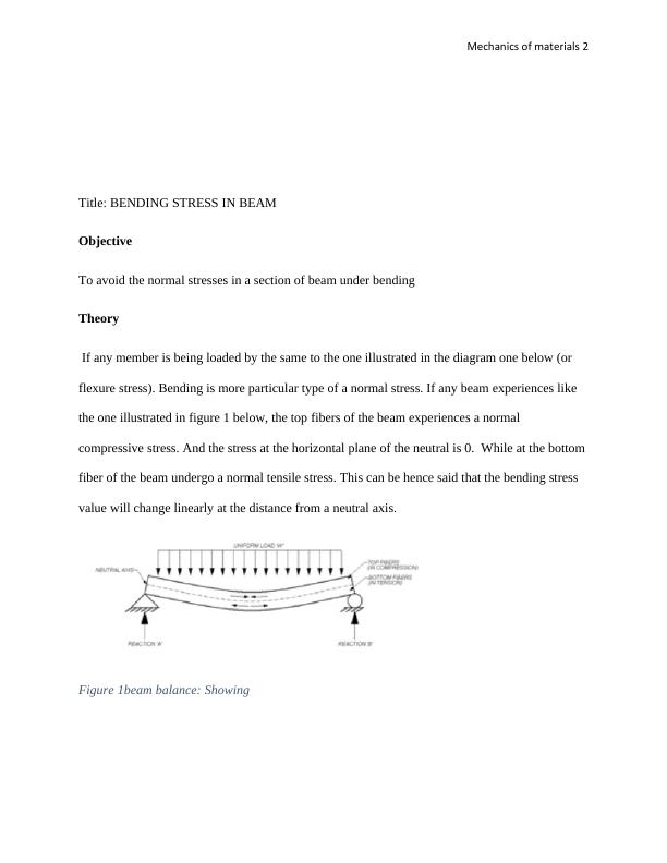
If any member is being loaded by the same to the one illustrated in the diagram one below (or
flexure stress). Bending is more particular type of a normal stress. If any beam experiences like
the one illustrated in figure 1 below, the top fibers of the beam experiences a normal
compressive stress. And the stress at the horizontal plane of the neutral is 0. While at the bottom
fiber of the beam undergo a normal tensile stress. This can be hence said that the bending stress
value will change linearly at the distance from a neutral axis.
Figure 1beam balance: Showing
Bending Stress in Beam_2
Mechanics of materials 3
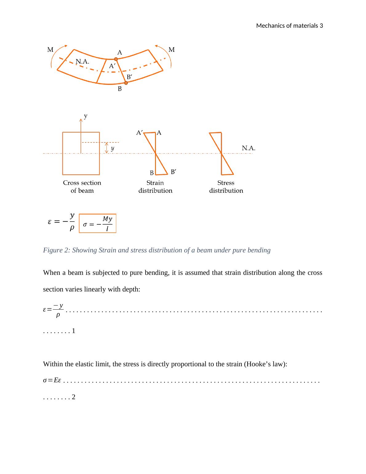
Figure 2: Showing Strain and stress distribution of a beam under pure bending
When a beam is subjected to pure bending, it is assumed that strain distribution along the cross
section varies linearly with depth:
ε = y
ρ . . . . . . . . . . . . . . . . . . . . . . . . . . . . . . . . . . . . . . . . . . . . . . . . . . . . . . . . . . . . . . . . . . . . . . . .
. . . . . . . . 1
Within the elastic limit, the stress is directly proportional to the strain (Hooke’s law):
σ = . . . . . . . . . . . . . . . . . . . . . . . . . . . . . . . . . . . . . . . . . . . . . . . . . . . . . . . . . . . . . . . . . . . . . . . .
. . . . . . . . 2
Bending Stress in Beam_3
Mechanics of materials 4
Therefore, a linear stress distribution across the section is expected (Figure 2), which can be
expressed by the flexural formula:
σ =My
I . . . . . . . . . . . . . . . . . . . . . . . . . . . . . . . . . . . . . . . . . . . . . . . . . . . . . . . . . . . . . . . . . . . . . .
. . . . . . . . . 3
Where;
ε = strain
σ = Stress (N/m2)
y = displacement w.r.t. neutral axis (m)
E = Young’s modulus (N/m2)
ρ = radius of curvature (m)
I = moment of inertia (m4)
Equipment used in the experiment
The equipment for this experiment is shown in Figure 3. It consists of:
A loading frame to apply 2 symmetrical point loads.
A load cell to measure the magnitude of force applied.
A number of strain gauges to measure strains at several locations across the beam
section.
A thumbwheel on the load cell to apply downwards load.
Bending Stress in Beam_4

End of preview

Want to access all the pages? Upload your documents or become a member.

Related Documents
Mechanics of Solids Report
|4
|594
|311

Thesis Title. Bending behaviour of steel fibre
|18
|4216
|22

Mechanical System
|8
|578
|76

Euler-Bernoulli Beam Theory in a Simply Supported Beam without Reinforcement
|12
|2463
|60

MECH204: Mechanics of Solids
|8
|1219
|229

Developing Sigma-Epsilon Curve for Bone Structure with Beam Theory
|8
|866
|67