ME503: Microwave Link Design for CPA & MIT, Melbourne, Australia
VerifiedAdded on 2023/06/13
|10
|2220
|189
Report
AI Summary
This report presents the design of a microwave communication link between Certified Practicing Accountants (CPA) and Melbourne Institute of Technology (MIT) in Melbourne, Australia. The report begins with an introduction to wireless communication, focusing on terrestrial microwave systems and their advantages, including higher data transmission rates and focused beams. It details the methodology for establishing a microwave link, including frequency planning, path profile construction, and Fresnel zone clearance. The report addresses atmospheric effects like rain and electromagnetic interference and their impact on signal propagation. A link budget analysis is performed, considering factors like transmitted power, antenna gains, and free-space loss, to ensure link feasibility. An economic evaluation, including cost-benefit analysis, is also conducted to assess the system's effectiveness. The design considers two possible solutions for a multimedia communication link between the organizations, with justification for the chosen implementation. The report concludes with references to relevant literature in the field of microwave communication systems. Desklib provides access to similar solved assignments and study resources for students.
UNIVERSITY AFFILIATION
DEPARTMENT OR FACULTY
COURSE ID & COURSE NAME
TITLE: DESIGN OF A COMMUNICATION LINK TO INTERCONNECT TWO
LOCATIONS
STUDENT NAME
STUDENT REGISTRATION NUMBER
DATE OF SUBMISSION
PROFESSOR (SUPERVISOR)
2018
DEPARTMENT OR FACULTY
COURSE ID & COURSE NAME
TITLE: DESIGN OF A COMMUNICATION LINK TO INTERCONNECT TWO
LOCATIONS
STUDENT NAME
STUDENT REGISTRATION NUMBER
DATE OF SUBMISSION
PROFESSOR (SUPERVISOR)
2018
Paraphrase This Document
Need a fresh take? Get an instant paraphrase of this document with our AI Paraphraser
DIGITAL MICROWAVE RADIO SYSTEMS
Introduction
Wireless communication has become a major means of communication since the 20th
century and it uses either the microwave or the radio waves. Terrestrial communication systems
enable wireless communication from one point to another with the transmit and receive signals
propagating in the atmosphere. Another alternative to the terrestrial communication system is the
satellite communication [1]. The choice of terrestrial communication is highly based on the
distance required to propagate a signal and the interferences in between the transceivers. Mobile
communication requires duplex communication for effective communication. most radio
channels are adopted when the communication techniques are half-duplex for instance, radio
broadcasting and the police walkie-talkie phones. All communication systems must contend with
noise or any other form of unwanted interference to guarantee quality of service. In any given
communication systems, there is a transmitter, encoder, and modulator [2]. The radio waves are
created using amplitude modulation whereby a message signal is transmitted by varying the
amplitude of a radio frequency carrier wave of fixed amplitude. During reception, the am
modulated wave is received, it undergoes a diode rectification and the radio frequency is filtered
using the appropriate well-designed filters to obtain the audio frequency signal [3]. For digital
encoding the pulse code modulation is implemented on the carrier wave to transmit the message
signal. The frequency range of a radio communication system lies between 3 to 300 Mhz.
Microwave systems allow for more data transmission based on high frequency where there is an
increased bandwidth and higher speeds. For some systems where the distances are relatively
short, the microwave antenna dimensions are altered to use smaller antennas and when longer
distances are required, larger antennas are used [4]. The small antenna can easily produce more
focused beams which are quite difficult to intercept or alter during transmission because of the
power density.
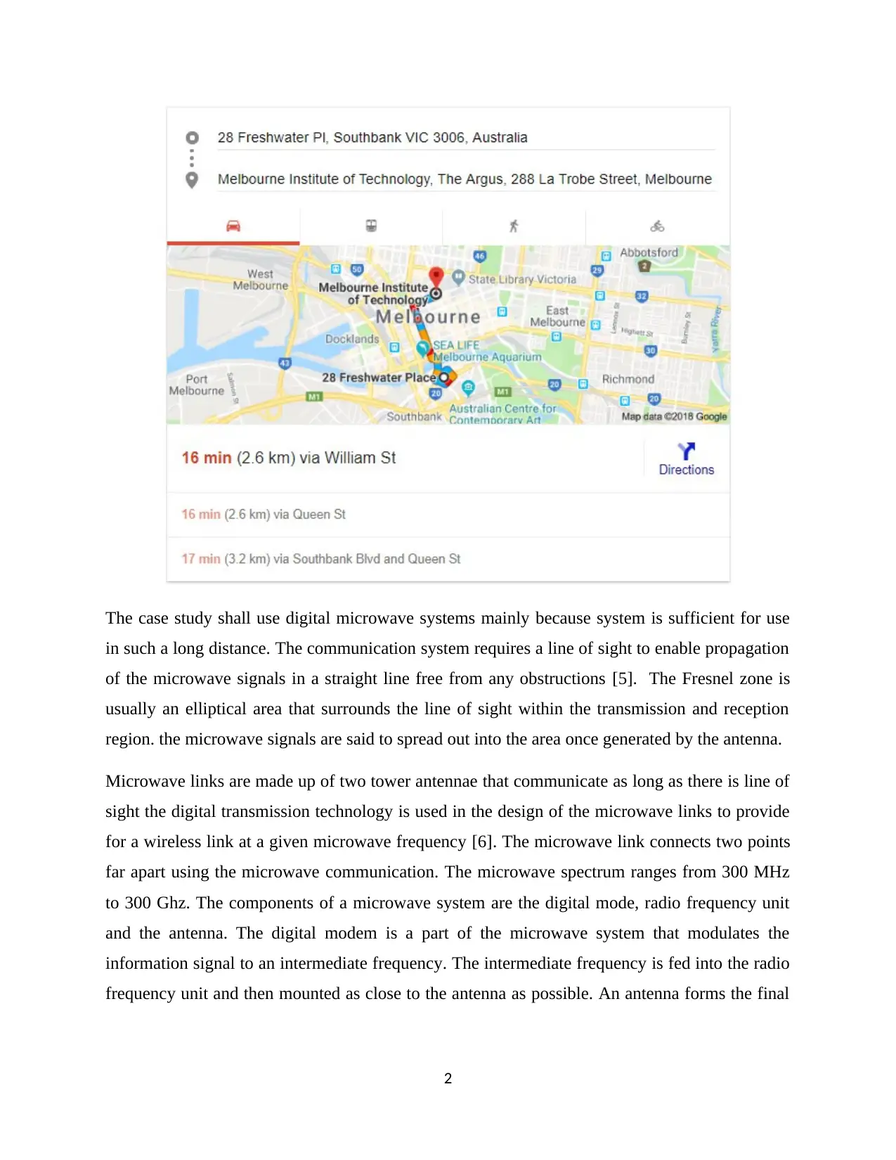
The case study here seeks to establish a microwave link between the CPA located at 28
Freshwater, PI, Southbank, Melbourne VIC 3006 and the Melbourne Institute of Technology
located on La Trobe St. VIC 3000 Melbourne. Implementing a microwave link between the two
buildings which are 2.6km apart,
1
The case study shall use digital microwave systems mainly because system is sufficient for use
in such a long distance. The communication system requires a line of sight to enable propagation
of the microwave signals in a straight line free from any obstructions [5]. The Fresnel zone is
usually an elliptical area that surrounds the line of sight within the transmission and reception
region. the microwave signals are said to spread out into the area once generated by the antenna.
Microwave links are made up of two tower antennae that communicate as long as there is line of
sight the digital transmission technology is used in the design of the microwave links to provide
for a wireless link at a given microwave frequency [6]. The microwave link connects two points
far apart using the microwave communication. The microwave spectrum ranges from 300 MHz
to 300 Ghz. The components of a microwave system are the digital mode, radio frequency unit
and the antenna. The digital modem is a part of the microwave system that modulates the
information signal to an intermediate frequency. The intermediate frequency is fed into the radio
frequency unit and then mounted as close to the antenna as possible. An antenna forms the final
2
⊘ This is a preview!⊘
Do you want full access?
Subscribe today to unlock all pages.

Trusted by 1+ million students worldwide
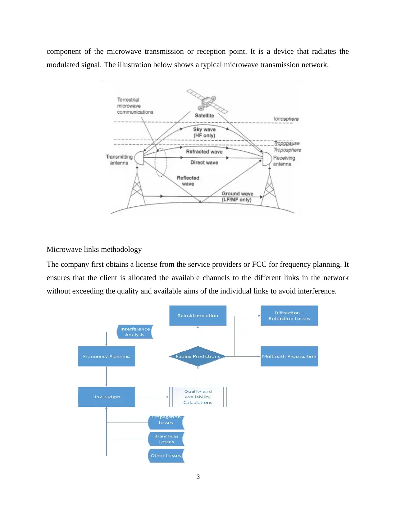
component of the microwave transmission or reception point. It is a device that radiates the
modulated signal. The illustration below shows a typical microwave transmission network,
Microwave links methodology
The company first obtains a license from the service providers or FCC for frequency planning. It
ensures that the client is allocated the available channels to the different links in the network
without exceeding the quality and available aims of the individual links to avoid interference.
3
Paraphrase This Document
Need a fresh take? Get an instant paraphrase of this document with our AI Paraphraser
Path profile construction
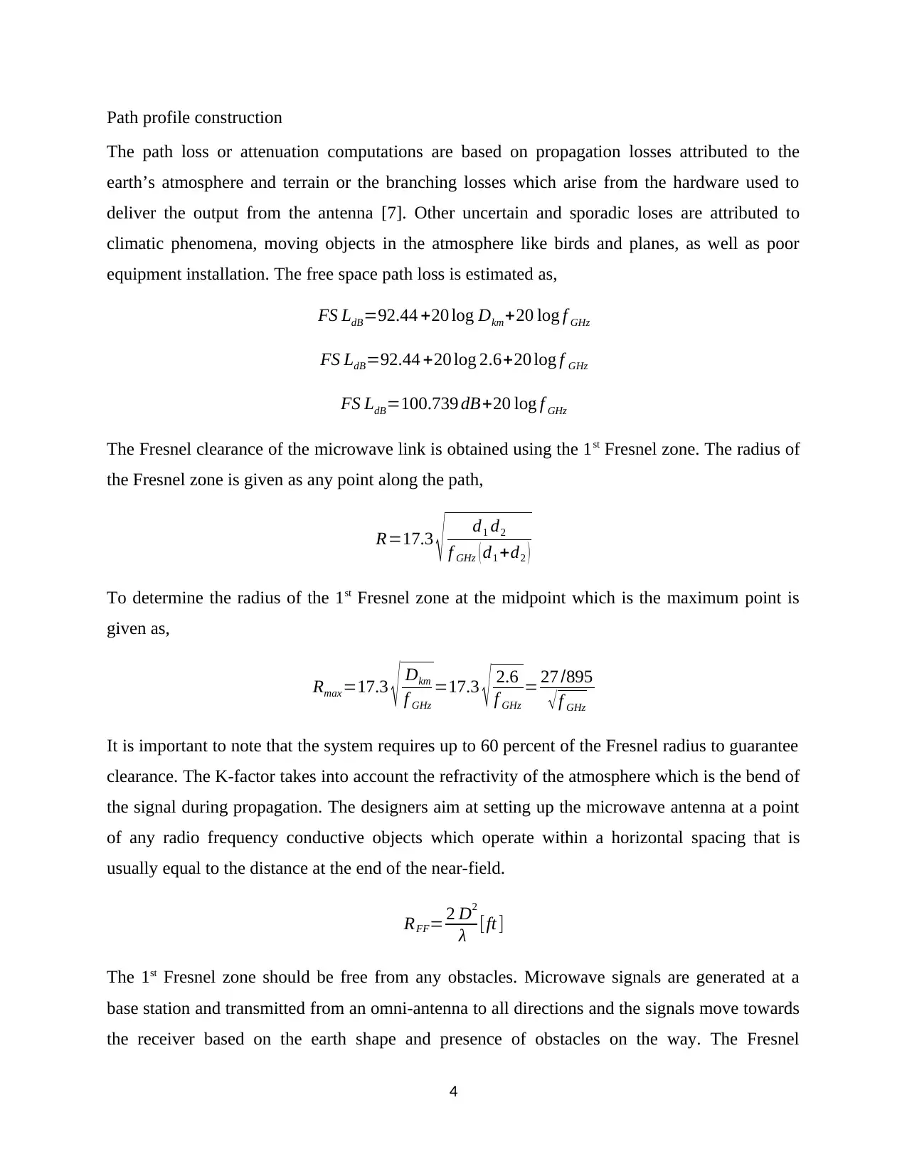
The path loss or attenuation computations are based on propagation losses attributed to the
earth’s atmosphere and terrain or the branching losses which arise from the hardware used to
deliver the output from the antenna [7]. Other uncertain and sporadic loses are attributed to
climatic phenomena, moving objects in the atmosphere like birds and planes, as well as poor
equipment installation. The free space path loss is estimated as,
FS LdB=92.44 +20 log Dkm+20 log f GHz
FS LdB=92.44 +20 log 2.6+20 log f GHz
FS LdB=100.739 dB+20 log f GHz
The Fresnel clearance of the microwave link is obtained using the 1st Fresnel zone. The radius of
the Fresnel zone is given as any point along the path,
R=17.3 √ d1 d2
f GHz ( d1 +d2 )
To determine the radius of the 1st Fresnel zone at the midpoint which is the maximum point is
given as,
Rmax =17.3 √ Dkm
f GHz
=17.3 √ 2.6
f GHz
= 27 /895
√f GHz
It is important to note that the system requires up to 60 percent of the Fresnel radius to guarantee
clearance. The K-factor takes into account the refractivity of the atmosphere which is the bend of
the signal during propagation. The designers aim at setting up the microwave antenna at a point
of any radio frequency conductive objects which operate within a horizontal spacing that is
usually equal to the distance at the end of the near-field.
RFF= 2 D2
λ [ft ]
The 1st Fresnel zone should be free from any obstacles. Microwave signals are generated at a
base station and transmitted from an omni-antenna to all directions and the signals move towards
the receiver based on the earth shape and presence of obstacles on the way. The Fresnel
4
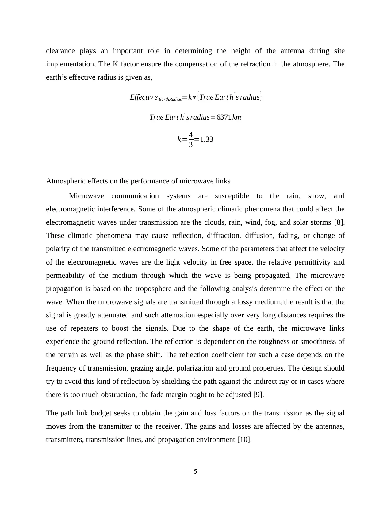
clearance plays an important role in determining the height of the antenna during site
implementation. The K factor ensure the compensation of the refraction in the atmosphere. The
earth’s effective radius is given as,
Effectiv e EarthRadius=k∗ ( True Eart h' s radius )
True Eart h' s radius=6371km
k = 4
3 =1.33
Atmospheric effects on the performance of microwave links
Microwave communication systems are susceptible to the rain, snow, and
electromagnetic interference. Some of the atmospheric climatic phenomena that could affect the
electromagnetic waves under transmission are the clouds, rain, wind, fog, and solar storms [8].
These climatic phenomena may cause reflection, diffraction, diffusion, fading, or change of
polarity of the transmitted electromagnetic waves. Some of the parameters that affect the velocity
of the electromagnetic waves are the light velocity in free space, the relative permittivity and
permeability of the medium through which the wave is being propagated. The microwave
propagation is based on the troposphere and the following analysis determine the effect on the
wave. When the microwave signals are transmitted through a lossy medium, the result is that the
signal is greatly attenuated and such attenuation especially over very long distances requires the
use of repeaters to boost the signals. Due to the shape of the earth, the microwave links
experience the ground reflection. The reflection is dependent on the roughness or smoothness of
the terrain as well as the phase shift. The reflection coefficient for such a case depends on the
frequency of transmission, grazing angle, polarization and ground properties. The design should
try to avoid this kind of reflection by shielding the path against the indirect ray or in cases where
there is too much obstruction, the fade margin ought to be adjusted [9].
The path link budget seeks to obtain the gain and loss factors on the transmission as the signal
moves from the transmitter to the receiver. The gains and losses are affected by the antennas,
transmitters, transmission lines, and propagation environment [10].
5
⊘ This is a preview!⊘
Do you want full access?
Subscribe today to unlock all pages.

Trusted by 1+ million students worldwide
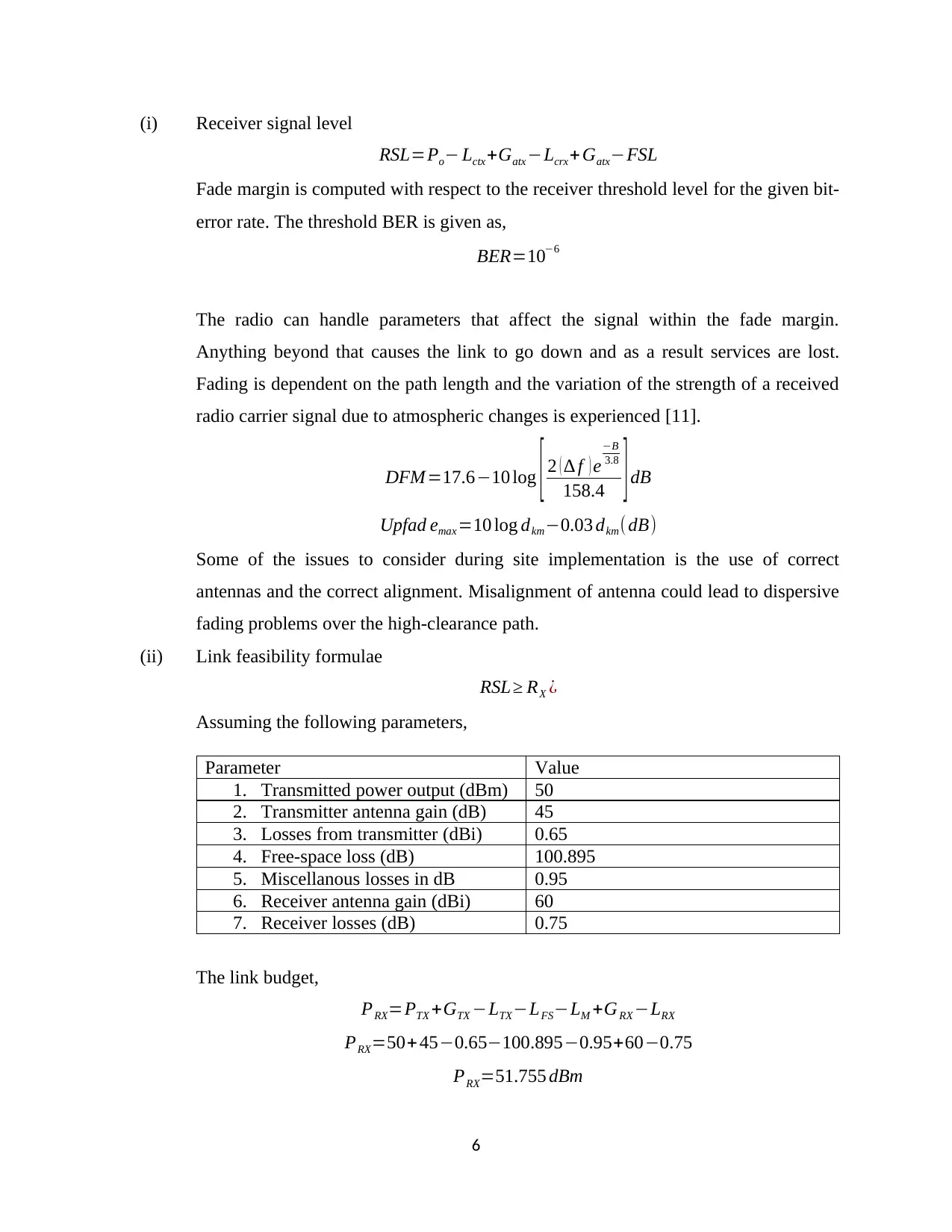
(i) Receiver signal level
RSL=Po− Lctx+Gatx −Lcrx+Gatx−FSL
Fade margin is computed with respect to the receiver threshold level for the given bit-
error rate. The threshold BER is given as,
BER=10−6
The radio can handle parameters that affect the signal within the fade margin.
Anything beyond that causes the link to go down and as a result services are lost.
Fading is dependent on the path length and the variation of the strength of a received
radio carrier signal due to atmospheric changes is experienced [11].
DFM =17.6−10 log [ 2 ( ∆ f ) e
−B
3.8
158.4 ]dB
Upfad emax =10 log dkm−0.03 dkm( dB)
Some of the issues to consider during site implementation is the use of correct
antennas and the correct alignment. Misalignment of antenna could lead to dispersive
fading problems over the high-clearance path.
(ii) Link feasibility formulae
RSL≥ RX ¿
Assuming the following parameters,
Parameter Value
1. Transmitted power output (dBm) 50
2. Transmitter antenna gain (dB) 45
3. Losses from transmitter (dBi) 0.65
4. Free-space loss (dB) 100.895
5. Miscellanous losses in dB 0.95
6. Receiver antenna gain (dBi) 60
7. Receiver losses (dB) 0.75
The link budget,
PRX=PTX +GTX −LTX−LFS−LM +GRX −LRX
PRX=50+ 45−0.65−100.895−0.95+60−0.75
PRX=51.755 dBm
6
Paraphrase This Document
Need a fresh take? Get an instant paraphrase of this document with our AI Paraphraser
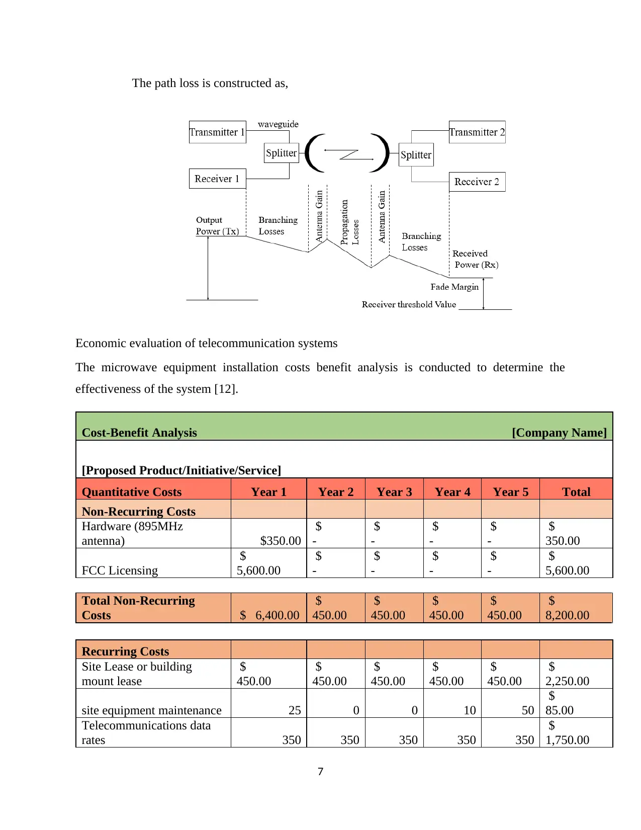
The path loss is constructed as,
Economic evaluation of telecommunication systems
The microwave equipment installation costs benefit analysis is conducted to determine the
effectiveness of the system [12].
Cost-Benefit Analysis [Company Name]
[Proposed Product/Initiative/Service]
Quantitative Costs Year 1 Year 2 Year 3 Year 4 Year 5 Total
Non-Recurring Costs
Hardware (895MHz
antenna) $350.00
$
-
$
-
$
-
$
-
$
350.00
FCC Licensing
$
5,600.00
$
-
$
-
$
-
$
-
$
5,600.00
Total Non-Recurring
Costs $ 6,400.00
$
450.00
$
450.00
$
450.00
$
450.00
$
8,200.00
Recurring Costs
Site Lease or building
mount lease
$
450.00
$
450.00
$
450.00
$
450.00
$
450.00
$
2,250.00
site equipment maintenance 25 0 0 10 50
$
85.00
Telecommunications data
rates 350 350 350 350 350
$
1,750.00
7
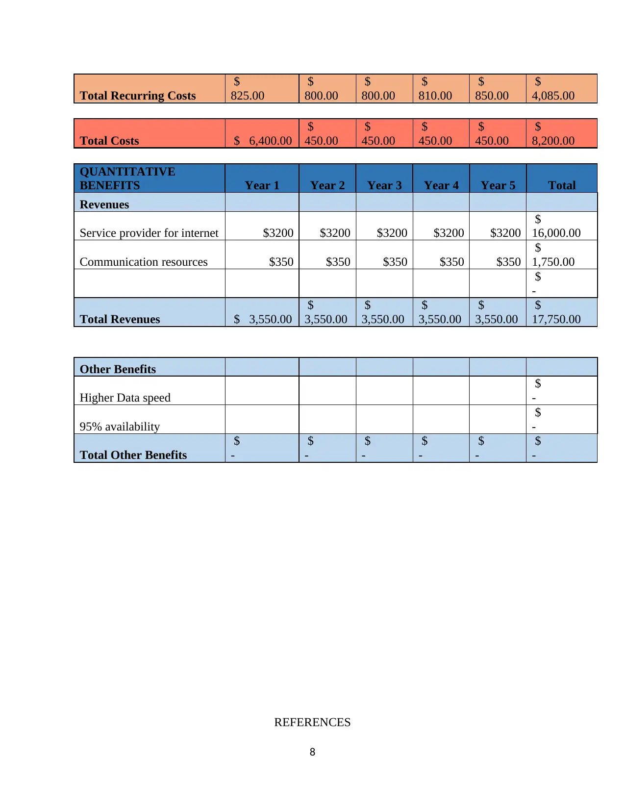
Total Recurring Costs
$
825.00
$
800.00
$
800.00
$
810.00
$
850.00
$
4,085.00
Total Costs $ 6,400.00
$
450.00
$
450.00
$
450.00
$
450.00
$
8,200.00
QUANTITATIVE
BENEFITS Year 1 Year 2 Year 3 Year 4 Year 5 Total
Revenues
Service provider for internet $3200 $3200 $3200 $3200 $3200
$
16,000.00
Communication resources $350 $350 $350 $350 $350
$
1,750.00
$
-
Total Revenues $ 3,550.00
$
3,550.00
$
3,550.00
$
3,550.00
$
3,550.00
$
17,750.00
Other Benefits
Higher Data speed
$
-
95% availability
$
-
Total Other Benefits
$
-
$
-
$
-
$
-
$
-
$
-
REFERENCES
8
$
825.00
$
800.00
$
800.00
$
810.00
$
850.00
$
4,085.00
Total Costs $ 6,400.00
$
450.00
$
450.00
$
450.00
$
450.00
$
8,200.00
QUANTITATIVE
BENEFITS Year 1 Year 2 Year 3 Year 4 Year 5 Total
Revenues
Service provider for internet $3200 $3200 $3200 $3200 $3200
$
16,000.00
Communication resources $350 $350 $350 $350 $350
$
1,750.00
$
-
Total Revenues $ 3,550.00
$
3,550.00
$
3,550.00
$
3,550.00
$
3,550.00
$
17,750.00
Other Benefits
Higher Data speed
$
-
95% availability
$
-
Total Other Benefits
$
-
$
-
$
-
$
-
$
-
$
-
REFERENCES
8
⊘ This is a preview!⊘
Do you want full access?
Subscribe today to unlock all pages.

Trusted by 1+ million students worldwide
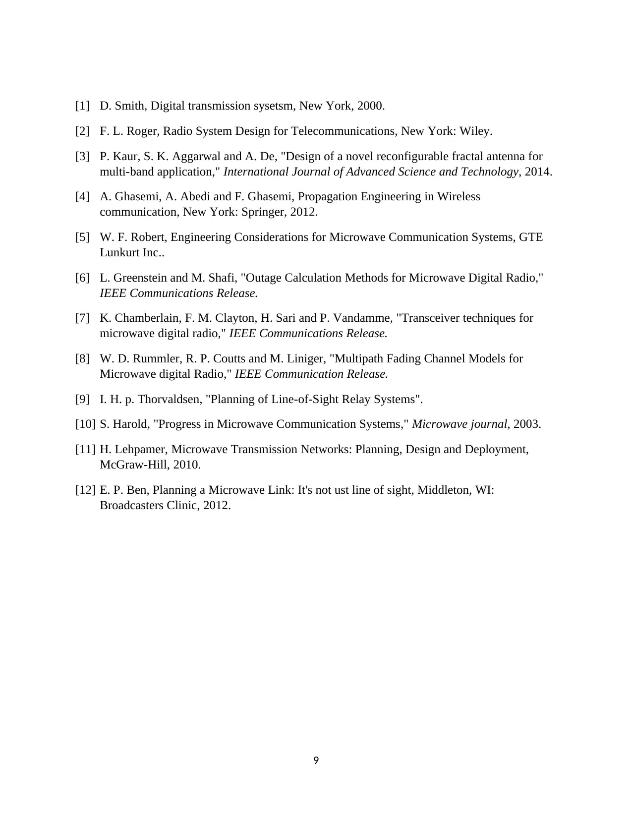
[1] D. Smith, Digital transmission sysetsm, New York, 2000.
[2] F. L. Roger, Radio System Design for Telecommunications, New York: Wiley.
[3] P. Kaur, S. K. Aggarwal and A. De, "Design of a novel reconfigurable fractal antenna for
multi-band application," International Journal of Advanced Science and Technology, 2014.
[4] A. Ghasemi, A. Abedi and F. Ghasemi, Propagation Engineering in Wireless
communication, New York: Springer, 2012.
[5] W. F. Robert, Engineering Considerations for Microwave Communication Systems, GTE
Lunkurt Inc..
[6] L. Greenstein and M. Shafi, "Outage Calculation Methods for Microwave Digital Radio,"
IEEE Communications Release.
[7] K. Chamberlain, F. M. Clayton, H. Sari and P. Vandamme, "Transceiver techniques for
microwave digital radio," IEEE Communications Release.
[8] W. D. Rummler, R. P. Coutts and M. Liniger, "Multipath Fading Channel Models for
Microwave digital Radio," IEEE Communication Release.
[9] I. H. p. Thorvaldsen, "Planning of Line-of-Sight Relay Systems".
[10] S. Harold, "Progress in Microwave Communication Systems," Microwave journal, 2003.
[11] H. Lehpamer, Microwave Transmission Networks: Planning, Design and Deployment,
McGraw-Hill, 2010.
[12] E. P. Ben, Planning a Microwave Link: It's not ust line of sight, Middleton, WI:
Broadcasters Clinic, 2012.
9
1 out of 10
Related Documents
Your All-in-One AI-Powered Toolkit for Academic Success.
+13062052269
info@desklib.com
Available 24*7 on WhatsApp / Email
![[object Object]](/_next/static/media/star-bottom.7253800d.svg)
Unlock your academic potential
Copyright © 2020–2026 A2Z Services. All Rights Reserved. Developed and managed by ZUCOL.


