logo

Modeling and Simulation: Enhancing System Performance and Design Optimization

Apply simulation tools to assess the mechanical performance of a component and optimize it to meet design objectives.

12 Pages3003 Words71 Views
   

Added on  2023-04-25

About This Document

In this document we will discuss about Modeling and Simulation and below are the summary points of this document:-

Modeling and Simulation: Enhancing System Performance and Design Optimization

Apply simulation tools to assess the mechanical performance of a component and optimize it to meet design objectives.

   Added on 2023-04-25

ShareRelated Documents
Modeling and Simulation
Name
Institution
Modeling and Simulation: Enhancing System Performance and Design Optimization_1
Executive Summary
Modeling and Simulation: Enhancing System Performance and Design Optimization_2
Modeling and Simulation
Introduction
In the contemporary world, many research projects and industry applications have embraced and
adopted the use of development systems in the study and design of different systems, as it takes
advantage of modeling and simulation to understand the performance of these systems, and thus
their optimization for improvement. Modeling and simulation refers to the creation and analysis
of a digital prototype of a design model in order to allow for the prediction of the performance of
this prototype when it is used for its intended applications in the real world. In so doing,
simulation modeling can be very useful for scientist and engineers who seek to understand the
mechanical performance of a system in order to establish the chances and conditions of failure,
by simulating the loads that the system can withstand (Hoogland, Karn, and Newhouse, 2010, p.
331). Simulation modeling has also found application in the fields of heat transfer and fluid flow
in the event that the mechanical performance of the system being designed will be affected by
either fluid flow or heat transfer. The simulation manages to assess the mechanical performance
of a system by making use of simulation software on the modeled digital prototype, such that the
loading conditions when the system is used for its intended purpose works remain within the
right range to predict any form of failure and thus prepare the system for these forces. For this
reason, simulation is specifically important for designing products in industry and validating
their structural integrity as it allows for the working conditions of the system to be simulated and
confirmed before the actual prototype is built (Ferreira, et al., 2013, p.42). This allows for the
optimization of the system design aspects like the mass, dimensions, volume, material type, and
cost, ensuring the system remains compatible with its intended purposes over time for an
increased effectiveness and precision in mechanical design.
The simulation process uses a digital prototype in either three dimensions or in planar form
which can be easily developed from a CAD tool. The CAD tool is then meshed in order to
identify the finite elements that will be used to model the variation of the conditions being
investigated on the digital prototype. Meshing is achieved through the use of algorithms which
break the entire design being simulated into a finite number of elements whose actual values for
each element can be easily calculated. The analysis of data for each of the finite element is done
considering the conditions being investigated, the constraints and the material used. The
boundary conditions greatly determine the distribution of the parameter we are interested in
within the system designed (Hoogland, Karn, and Newhouse, 2010, p. 331). The results obtained
are then used to make engineering decisions as may be required based on the goal of simulation.
Examples of software used in mechanical engineering design include ANSYS, MATLAB,
Solidworks, Anylogic, and the Autodesk framework, among others.
Objective
Modeling and Simulation: Enhancing System Performance and Design Optimization_3
In this study, the use of simulation tools was required for the design of a cantilever bracket in
order to assess if the design has met the design criteria that was specified for it and thus the
mechanical performance of the bracket as well as optimizing it to suit the specific objective of
designing the component. The cantilever design will entail a 10mm thick alloy steel whose
physical properties are:
Elastic Modulus = 210GPa
Poisson's Ratio = 0.28
Yield Strength = 620.42MPa
Density = 7700Kg/m3
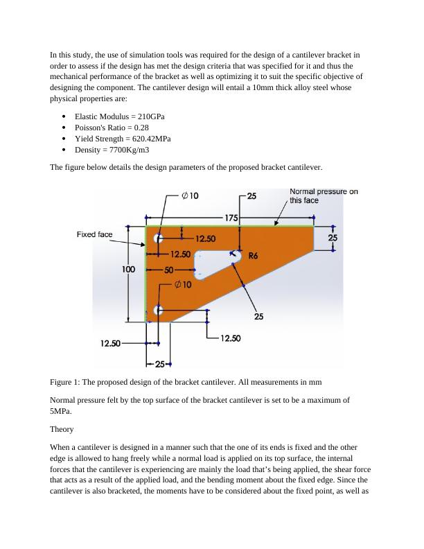
The figure below details the design parameters of the proposed bracket cantilever.
Figure 1: The proposed design of the bracket cantilever. All measurements in mm
Normal pressure felt by the top surface of the bracket cantilever is set to be a maximum of
5MPa.
Theory
When a cantilever is designed in a manner such that the one of its ends is fixed and the other
edge is allowed to hang freely while a normal load is applied on its top surface, the internal
forces that the cantilever is experiencing are mainly the load that’s being applied, the shear force
that acts as a result of the applied load, and the bending moment about the fixed edge. Since the
cantilever is also bracketed, the moments have to be considered about the fixed point, as well as
Modeling and Simulation: Enhancing System Performance and Design Optimization_4

End of preview

Want to access all the pages? Upload your documents or become a member.

Related Documents
Comparison of Inlet and Outlet Velocity of Fluid in Rectangular Pipe
|19
|2311
|451

Nonlinear Elastic Plastic Finite Element Analysis of U-Shaped Plate (2D and 3D)
|8
|2765
|19

Procedia Engineering | Assessment1
|8
|1443
|40

Structural Assessment of Bicycle Crank using Finite Element Analysis
|10
|1288
|301

Assignment on Finite Element Analysis – Vibration of a Box, Stress in a Plate
|15
|1860
|17

Finite Element Analysis
|9
|1446
|365