Communication Systems Assignment: Modulation, Error Detection, WLAN
VerifiedAdded on 2023/06/03
|17
|2315
|81
Homework Assignment
AI Summary
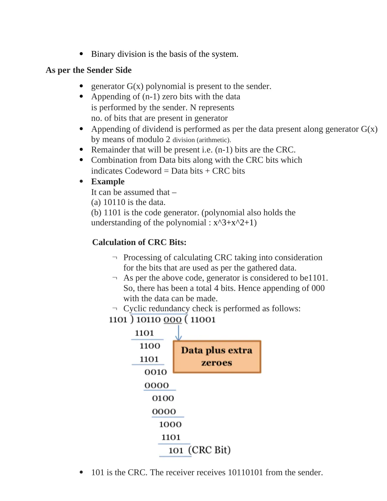
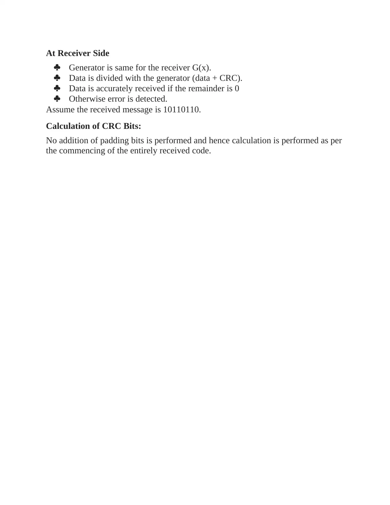
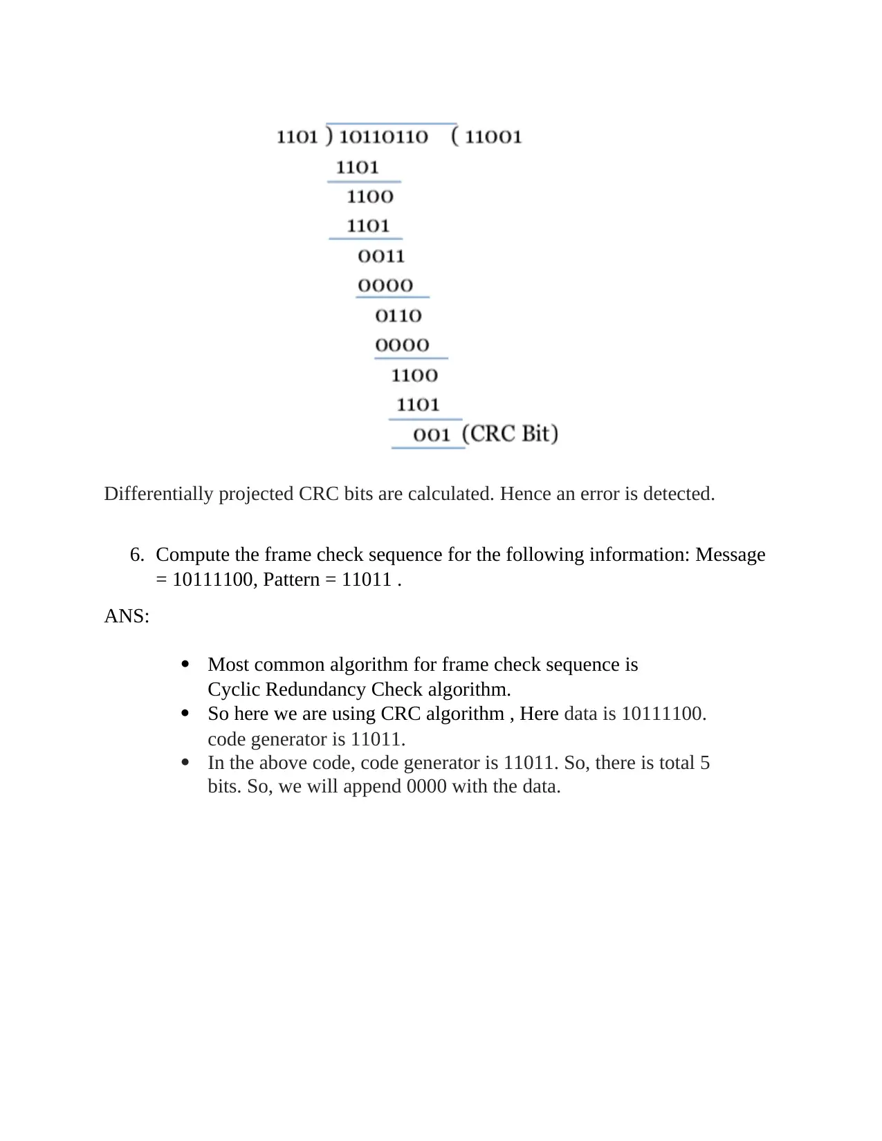
This document provides a comprehensive solution to a communication systems assignment. It begins by detailing various analog modulation techniques, including ASK, FSK, PSK, DPSK, and multilevel ASK and PSK, converting a binary data sequence into analog waveforms. The solution then computes frequency assignments for a 16-level FSK system. Further, it includes drawings of analog and frequency modulation waveforms. The assignment also covers the creation of a 16 QAM constellation diagram and provides a detailed explanation of the error detection process using Cyclic Redundancy Check (CRC), including computations for a given message and pattern. The solution extends to the analysis of Direct Sequence Spread Spectrum (DSSS) signal transmission and compares the differences between infrastructure and ad-hoc modes in WLAN, including comparative illustrations. Finally, the document explains the preference for hexagonal shapes in cellular communication.
1 out of 17
Related Documents


Your All-in-One AI-Powered Toolkit for Academic Success.
+13062052269
info@desklib.com
Available 24*7 on WhatsApp / Email
![[object Object]](/_next/static/media/star-bottom.7253800d.svg)
Copyright © 2020–2026 A2Z Services. All Rights Reserved. Developed and managed by ZUCOL.