VLAN Configuration on Switch and Router
VerifiedAdded on 2020/05/08
|31
|7490
|73
AI Summary
This assignment presents a step-by-step guide to configuring VLANs on both a switch and a router. It details the creation of multiple VLANs (30-60) on the switch, assigning IP addresses within each VLAN, and enabling their interfaces. The configuration also includes setting up a router interface (GigabitEthernet0/0) connected to the switch's VLAN 50, with an appropriate IP address and static route pointing to the VLAN 50 network.
Contribute Materials
Your contribution can guide someone’s learning journey. Share your
documents today.
Running head: IT NETWORKING DESIGNING
IT Networking Designing
Name of the Student
Name of the University
Author’s Note
IT Networking Designing
Name of the Student
Name of the University
Author’s Note
Secure Best Marks with AI Grader
Need help grading? Try our AI Grader for instant feedback on your assignments.
1
IT NETWORKING DESIGNING
Executive Summary
The report is set up for outlining and designing a system utilizing different system interface that
are associated with routers and switches. A layer three switch is utilized for planning the system
and the Pc connected in different department of the head office of Infocolllege.edu College. The
LAN solution is proposed according to the requirement of the organization and different servers
are installed in the network and allowed access from departments for increasing the productivity
of the network. The web server is designed with HTTP for serving the customer clients with the
pages and react to their demand. A firewall is arranged in the system and the router is configured
with access control list for blocking the different departments to communicate with each other
and increase the security of the network.
2
IT NETWORKING DESIGNING
Table of Contents
1. Examination of the different network principles and protocols......................................4
1.1. Introduction...............................................................................................................4
1.2. Benefits and constraints of different types of network and standards......................4
1.3. Impact of the network topology................................................................................5
1.4. Communication and bandwidth requirement............................................................6
2. Network Device and operation........................................................................................9
2.1. Operating principles of networking devices and types of servers............................9
2.2. Inter dependency of workstation hardware and relevant network software...........10
3. Designing efficient network systems.............................................................................11
3.1. Design of the network system.................................................................................11
3.1.1. Description of the LAN technology and topology used in the network..........11
3.2. Testing and evaluation of the design......................................................................12
3.2.1. Description and justification of the device used in the network......................12
3.2.2. Suggestion and maintenance schedule for supporting the network system.....13
3.2.3. Production of test plan.....................................................................................14
4. Implementation of the test and diagnosis of the networked system..............................16
4.1. Implementation of the designed network based on the network specification.......16
4.2. Documentation and analysis of the test result........................................................17
3
IT NETWORKING DESIGNING
4.3. Investigation of the ability of the network for growth and communicating with the
other devices..............................................................................................................................17
5. Conclusion.....................................................................................................................19
References..........................................................................................................................21
Appendices........................................................................................................................26
Configuration of the layer 3 switch installed in the network.........................................26
Secure Best Marks with AI Grader
Need help grading? Try our AI Grader for instant feedback on your assignments.
4
IT NETWORKING DESIGNING
1. Examination of the different network principles and protocols
1.1. Introduction
The report is prepared for infocollege.edu to design the network with a complete LAN
technology and connect the other branches of the college located in Birmingham, Liverpool,
Manchester and Glasgow. The network is designed for the central head office located in London
such that it can communicate with the other branches and manage the information of the college
from a central point. The LAN solution is prepared with the private IP address of 192.168.5.0/ 24
and it is made flexible to adopt the future requirement of the college to grow its network
according to the changes in the requirement of the college. The network solution is designed with
the application of new technologies and different subnets are used for the different departments
for reducing the wastage of the IP address and increasing the efficiency of the proposed network
solution (Witten et al. 2016). An IP addressing plan is created for the network solution and
attached with the report for future assistance and configure the network device according to the
addressing plan. Some extra bits of address are reserved for each of the department of the college
such that the network can accommodate the future growth of the college and the servers are
configured according to the requirement of the college to handle emails and file request from the
college.
1.2. Benefits and constraints of different types of network and standards
The selection of the network topology is important for connecting the different
department in the organization and the structure of the network is used for defining the
communication standards maintained in the proposed network solution. There are advantages
and disadvantages associated with the implementation of the different network topology and
5
IT NETWORKING DESIGNING
each of the elements used in the designing of the network should be listed for making a physical
and logical framework of the network. There are different types of network such as LAN, WAN,
WLAN, MAN, SAN, CAN, PAN and the each have its application in differ5ent field of the
network.
The local area network is used for connecting the device in the network located at a short
distance and it may be home, school buildings, office. It is mainly applied in TCP//IP network
and not used as a single subnet for connecting the devices in the network. The wide area
network is used as a collection of LANs where the router maintains the records of the LANs used
in the network and the WAN spreads over a larger distance than the LAN and a router is used for
inter connecting the devices installed in the network (Sahhaf et al. 2015). In wide area network
the network can be segmented and different subnets and IP address can be used on different
interface of the devices. WAN uses different technology such as frame relay, ATM, etc. for
establishment of a secure connection between the nodes. Moreover there are other types of
network such as metropolitan area network and campus area network that are used for spanning
multiple LANs and connecting different data centers with high speed connection.
1.3. Impact of the network topology
The selection of the right network topology is important for increasing the efficiency of
communication between the nodes connected in the network. The network cabling plan is
important for accommodation of the growing needs of the organization and reducing the
congestion in the network traffic. The network used for head office in London should be fully
connected with the other branches and offices such that the resources of the private college is
available to the network administrator (Rezha and Shin 2014). The cost of the network,
scalability and availability is considered before selection of the network topology and
6
IT NETWORKING DESIGNING
implementation in the head office LAN solution. For securing the different components in the
network privacy should be maintained and proactive routing is configured for communicating
with the other branches and offices of the college. The advantage that can be gained with the
configuration of the router with proactive routing is that the waiting time is less but there is a
disadvantage that with the increase in the traffic in the network the CPU load increases. Thus the
increase in the congestion can decrease the performance of the organization and impact the
growth of the organization (Sadique and Shah 2016). The transmission links used for
interconnecting the devices should be up and a core components of the network such as the
servers and the routers should be kept out of reach from the staffs for reducing the risk of
physical assault.
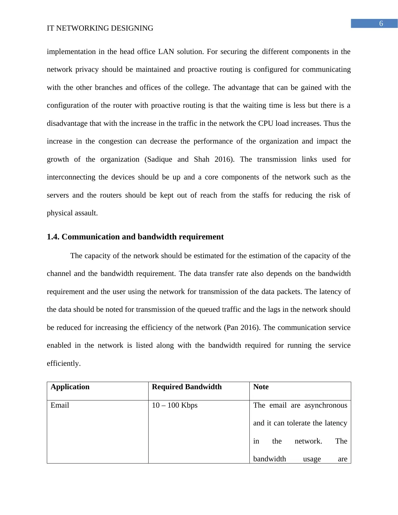
1.4. Communication and bandwidth requirement
The capacity of the network should be estimated for the estimation of the capacity of the
channel and the bandwidth requirement. The data transfer rate also depends on the bandwidth
requirement and the user using the network for transmission of the data packets. The latency of
the data should be noted for transmission of the queued traffic and the lags in the network should
be reduced for increasing the efficiency of the network (Pan 2016). The communication service
enabled in the network is listed along with the bandwidth required for running the service
efficiently.
Application Required Bandwidth Note
Email 10 – 100 Kbps The email are asynchronous
and it can tolerate the latency
in the network. The
bandwidth usage are
Paraphrase This Document
Need a fresh take? Get an instant paraphrase of this document with our AI Paraphraser
7
IT NETWORKING DESIGNING
significant for attachment of
the large doc files, spams,
viruses.
Messaging < 10 Kbps The messaging traffic are
infrequent and thus it can
tolerate high latency in the
network.
Web Browsing 64 – 100+ Kbps It is used for requesting of
data and asynchronous
communication is used and a
fair lag can be tolerated in the
network. The bandwidth
requirement increases with
the increase in the request
from the users for getting
more data, long downloads,
etc.
Audio Streaming 96 -160 Kbps The streaming service
requires a large bandwidth
and a large buffer can be
introduced for reducing the
latency of bandwidth. If
extended period of lag is
8
IT NETWORKING DESIGNING
faced in the network the
streaming can fail and it can
occur outrage of the session.
VOIP 24 – 100+ Kbps It requires constant
bandwidth and no lag in the
network can be tolerated
because it can cause call drop
and miscommunication may
happen.
Video Streaming 96 – 200+ Kbps It is similar with audio
streaming and the latency can
be avoided by using large
buffer size and high
throughput is required for the
working of the video
streaming properly.
File Sharing 0 – infinity Mbps For setting up a peer to peer
network the any amount of
latency can be tolerated and
the throughput can be used
for transmission of the data to
the clients connected in the
network.
9
IT NETWORKING DESIGNING
Thus for the estimation of the bandwidth necessary for the communication the expected
number of users are multiplied by the application used by them and calculate the total bandwidth.
2. Network Device and operation
2.1. Operating principles of networking devices and types of servers
The different networking connected in the network operates on different principles and
different medium can be used for the establishment of the connection between the nodes installed
in the network. The devices uses the different layers of the OSI model and the devices are
categorized into five different categories for transmission of the data packets in the network. The
categories are gateway, routing or layer three switch, layer 2 switch or bridge, hub or repeater
and passive hubs (Quinn and Guichard 2014). The switch is used as the central point for
connecting the different devices and the switch are of different types such as the layer 3 and
layer 2 switch. Several number of network cables can be plugged from different device for
communicating with each other. The business policy of the organization is configured in the
network for restricting the departments to communicate with the other department (Lu et al.
2016). The repeater are used for long distance communication and regeneration of the signal for
reducing the loss of data in the network. Bridge or layer 2 switch is used for checking the
destination address and forwarding the data packets in the destination network. The traffic in the
network can be filtered by creation of different vlans for the different departments and blocking
the vlan to communicate with the departments (Lu, Yu and Yao 2014). The layer three switch is
configured with access control list according to the business policy for meeting the requirement
of the organization and maintaining a smooth transition in the network. Different types of servers
are usd in the network such as the email, web, dns and file server and the servers are connected
Secure Best Marks with AI Grader
Need help grading? Try our AI Grader for instant feedback on your assignments.
10
IT NETWORKING DESIGNING
in a different vlan and allowed access to all the departments for increasing the performance of
the network solution.
2.2. Inter dependency of workstation hardware and relevant network software
The hardware of the workstation used in the organization is interdependent with the
application and network software installed in the machines. Some of the network software are
designed for handling multiple processing and consumes large amount of memory and thus the
workstation hardware should be compatible to run different application software. The traditional
workstation uses PCI 32 bit version and it may be insufficient for handling huge number of
request and wider bus with high data transmission rate should be installed (Oinas-Kukkonen
2013). The network server used in the network are installed with a network operating system for
the management of the entire network and respond to the request coming from different clients in
the network (Larsson et al. 2014). If the load of the network increases and the hardware should
support virtualization for handling the request and reducing the load on the network. The
virtualization of the network server can increase the efficiency of the network and reduce the
waiting time of the user and thus improving the overall production of the organization
(Mehrpouyan et al. 2014). The interdependency should be identified during the design phase and
the security measures should be applied for the improvement of the organizational framework.
The security measures should be applied and the network should be tested for ensuring that the
unforeseen vulnerabilities in the network are identified (Oliviero and Woodward 2014). Training
should be given to the users such that the staffs does not installs unwanted applications in the
workstation because it may open path for the hackers to intrude into the organizational network
and hack the organizational data.
11
IT NETWORKING DESIGNING
3. Designing efficient network systems
3.1. Design of the network system
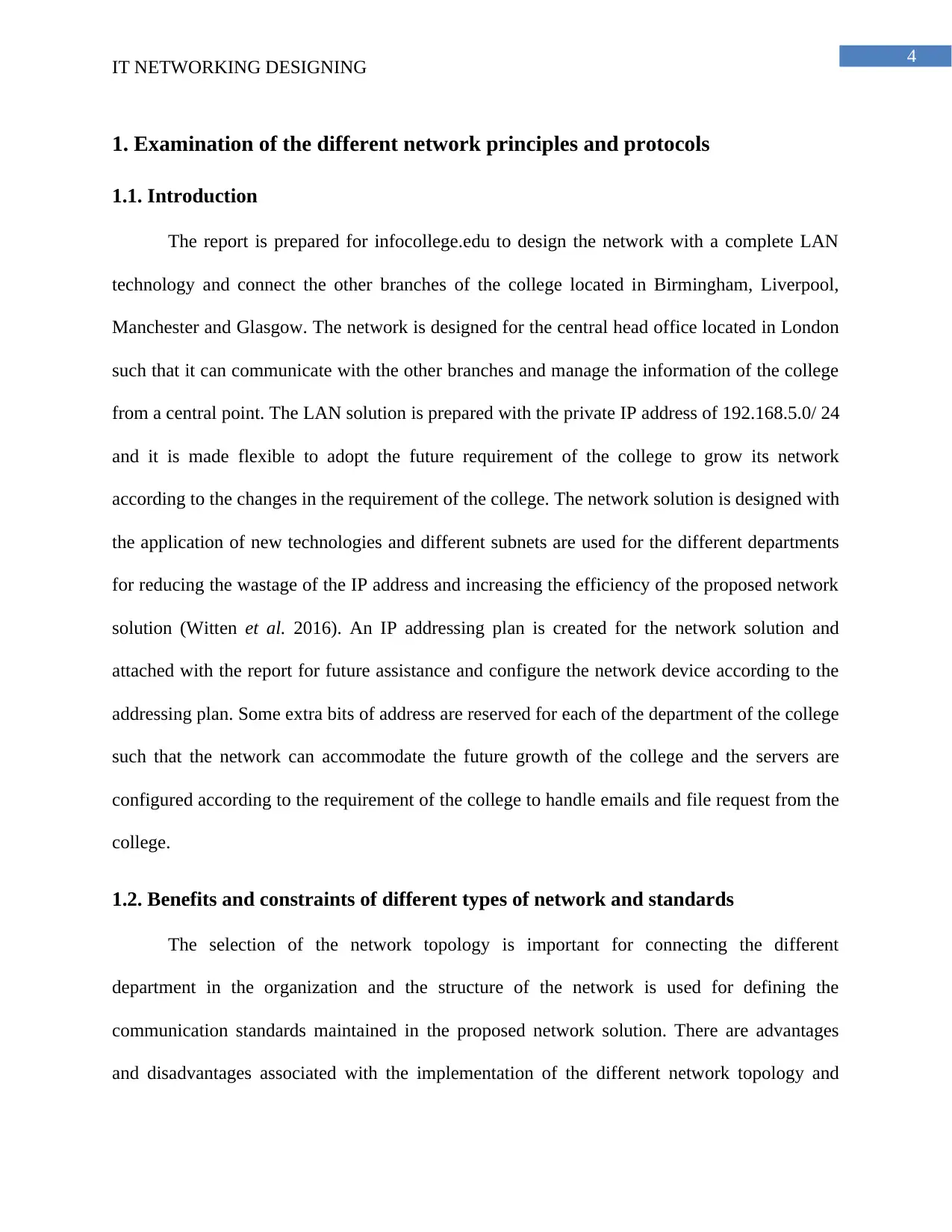
Figure 1: Physical topology of the proposed network solution
(Source: Created by author)
3.1.1. Description of the LAN technology and topology used in the network
A hybrid framework is followed for designing the local area network of the London
office and separate vlans are created for the different departments of the office. The servers are
connected to a separate vlan and a layer three switch is used for management of the LAN and
routing between the different devices connected in the network. The three layer topology is used
and it consists of a core layer that consists of the servers and the switches and it connected with
each other. The lan technology works on vlan and creation of the separate vlan increases the
security of the network (Lannoye, Flynn and O'Malley 2015). The department cannot access the
12
IT NETWORKING DESIGNING
nodes of other department directly and they can communicate with each other via the mail, web
or the file server installed in the network. The environment of the local area network is protected
using antivirus software to protect the network from unauthorized agents and security patches are
installed after a regular interval of time for taking precaution against illegal access of the
components of the organizational network solution (Osseiran et al. 2013). The router is
configured with access control list from blocking the unauthorized users to access the main core
components of the network and increase the security of the network (John et al. 2013). The inter
communication between the different departments are blocked according to the business policy
and the unused ports of the switches and the routers are blocked such that it cannot be used for
sending or receiving data packets in the network.
3.2. Testing and evaluation of the design
3.2.1. Description and justification of the device used in the network
For the implementation of the network devices a list of the equipment required, software
and service required is analyzed and a proper cabling plan is created for interconnecting the
devices in the network. A network cables should be tested and a documentation is provided for
certification of the standards maintained in the whole process of cable installation in the network.
The core components should be identified such as the routers, layer three switches and the power
supply should be checked for correct operation and the UPS must be installed for handling
fluctuation of the voltage (Hayajneh et al. 2014). On account of certain high-esteem things of
gear (for instance, a center switch costing a huge number of pounds), the hardware merchant
may complete establishment and testing for the benefit of the customer, and will give all vital
documentation (Sadique and Shah 2016). System availability and access to client information
and applications can be tried by signing into the system from haphazardly chose workstations
Paraphrase This Document
Need a fresh take? Get an instant paraphrase of this document with our AI Paraphraser
13
IT NETWORKING DESIGNING
utilizing a nonexclusive client account (on an expansive system, it may not be handy to check
each and every client account independently). Access to email, the Internet, organize printing
and different administrations will likewise be tried (Gould and Lavu 2014). Once the
association's information has been exchanged from the old framework to the new framework,
reinforcement systems ought to be thoroughly tried to guarantee that they work accurately.
The documentation of the network includes inclusion of the network cabling plan, floor
plan and the schematic for demonstration of the location where the network devices are installed
in the network. The details of the network device should be maintained with the details of the
technical specification and the software license and version used in the device for maintenance of
the network components (Fitouhi and Nourelfath 2014). The MAC and IP address of every
gadget on the system ought to likewise be recorded and cross referenced to a physical area. The
accessibility of point by point and precise system documentation makes the errand of overseeing
and investigating the system and doing routine upkeep and repairs significantly simpler (Shen et
al. 2015). Support can be given to clients much more rapidly and viably if the assistance work
area can distinguish the introduced programming, equipment setup, organize address and
physical area of a client's workstation before an IT professional is dispatched to examine the
issue.
3.2.2. Suggestion and maintenance schedule for supporting the network system
For the implementation of the network the numerous task involved for the development
of the network infrastructure should be commenced and other task should be identified and
description of each of the plan should be given. The start and the end duration of the project
should be developed and the resources should be allocated for completion of each of the phases
of development of the network infrastructure. The network administrator should use network
14
IT NETWORKING DESIGNING
protocol analyzer for identification of the errors in the network and testing should be done to
reach all the parts of the network (Giambene 2014). The ping failure should be checked and the
implementation of the network devices should be controlled for listing the material required for
the completion of the development of the network solution. A unit testing should be performed
such that the post installation process is checked and the activity is performed for scheduling the
maintenance of the network components. An operating system and the antivirus software
installed in the workstations should be updated regularly for defending against the viruses and
spywares and protect the network from unauthorized intruders (Castel and Church 2013). For
maintenance of the network the traffic flow should be monitored and the irregular behavior in the
network traffic should be monitored and analyzed. The device should be password protected and
the communication channel should be encrypted for protecting the network from loss of data.
Regular maintenance of the network device would reduce the risk of network failure and a
backup plan should be created for the management of the emergency situation.
3.2.3. Production of test plan
For the production of the network test plan the following things should be covered up
such as:
Definition of the objectives of the network
It should be ensured that the network is scalable and available all the times and operates
flawlessly with the increase in the load in the network. The transmission speed should not be less
the business rules of the organization should be aligned for the development of the infrastructure
of the network (Dankar et al. 2013). The backup created should work and the network should be
able to recover from any error immediately after any failure. The network should also meet the
security needs and the performance of the network should never be down.
15
IT NETWORKING DESIGNING
Definition of the acceptance criteria
All the result of testing of the network should be positive and an initial run should be
made for the identification of the priority errors and correction of the errors for returning to the
test result (Alonso, Opalko and Dostert 2015). A documentation should be created mentioning
the medium and the low faults in the network and defining the process used for the solvation of
the errors.
Definition of the schedule
The high level activity included in the designing of the network should be included in the
network documentation and the expected start and the completion date for deployment of the
different network device should also be included in the project plan.
Definition of the roles and responsibility
The roles and the responsibility of the development team should be included in the test
plan for minimizing the errors in the project (Barry et al. 2015). A network tester should be
appointed for testing the connectivity of the devices installed in the network and resolve the error
immediately identified during the development of the network infrastructure.
Definition of the resources
The hardware, staffs and the software required for the development of the network
framework should be identified and aligned with the network development stages for
development of the network successfully (Gerçekcioglu 2014). It should be confirmed that the
network deployment plan should meet the requirement.
Definition of the procedures
Secure Best Marks with AI Grader
Need help grading? Try our AI Grader for instant feedback on your assignments.
16
IT NETWORKING DESIGNING
Test cases should be developed and it should be followed during the testing of the
network and the test case should include test script for conducting the test and verification of the
network connectivity between the nodes connected in the network (Hu and Qian 2014). The test
result should be verified and documented for finishing the test.
4. Implementation of the test and diagnosis of the networked system
4.1. Implementation of the designed network based on the network specification
The servers should be configured and a prototype of the network should be created for
the evaluation of the network meeting the requirement of the organization. The users connected
in the network should be blocked from using the core network components and interconnection
between the different branches should be created by configuring the router installed in the head
office (Armbrust et al. 2015). DHCP address is used for the VLANs it should be noted that the
default gateway address used for the vlan should be available for any of the host connected in the
vlan because it can be used for by passing the proxy server and reach the other nodes connected
in the network (Yan et al. 2013). A performance analysis is done on the network core
components and the device available for implementation in the current network solution for
meeting the objectives of the organization. The features and the functionality of the network
solution is identified and test plan is developed performing the task assigned to the testing team
and the use of the spanning tree in the switch for the allocation of the IP address to the different
vlans connected with the layer three switch (Cook et al. 2013). The identification of the
configuration is important and the IP address used on the interface should be analyzed for the
development of the net wok infrastructure without any errors in the final network solution. The
network administrator and the testing team should work as a team for resolving the errors in the
17
IT NETWORKING DESIGNING
network and improve the network performance for reducing the lag and increasing the efficiency
of the organizational network.
4.2. Documentation and analysis of the test result
Test result should be analyzed and a standardized structure should be created and a
quality plan should be created for the verification of the analysis test result and verification if the
documented (Yang, Park and Choi 2017). The test result should meet all the quality aspects of
the network and the major cause of the failure of the network should be aligned of the
development of the network infrastructure. A strategy should be followed for testing the
components in the network and a quality guideline should be created for setting the project and
identification of the key network elements across the network (Katano, Nuggehalli and Kim
2016). The strategy should be followed for the lifecycle of network development and analysis of
the test item should include the features and approach for evaluation of the pass and fail of the
artifacts used in the network. The faulty nodes should be identified and change in the network
topology for meeting the requirement should also be analyzed for increasing the efficiency of the
network and the implementation of the external network components should be used for the
identification of the errors in the network and increasing the efficiency of the network solution
(Huang, Hsieh and Wu 2014). A performance analysis is done on the hardware device installed
in the network and a proper network addressing scheme is used for allocation of the IP address to
the device connected in the network. The device are pinged with the IP address for testing the
connectivity in the network. The calculation of the energy consumption and the transmission
time for the transfer of the data packets should be identified for the connection of the hosts in the
network.
18
IT NETWORKING DESIGNING
4.3. Investigation of the ability of the network for growth and communicating with
the other devices
The created network infrastructure is evaluated for scalability and it is found that the
network can be used for the future growth of the organization following the IP addressing plan.
Extra bits of address are stored in reserve for the accommodation of the increased number of host
and connect in the different vlans of the department for handling more number of customer
request. The servers installed in the network can be virtualized for increasing the efficiency of
the network and handle more number of client request at a time (Cordray et al. 2015). The
physical links between the devices are analyzed for identification of the limitation of the
bandwidth of the network and it is found the network is able to accommodate the new host and
more vlan can be configured for opening new departments and connecting it with the other
department of the head office (Wu et al. 2014). The Ip and DNS management is important for
the expansion of the network and the network service allowed in the network should be allowed
for increasing the productivity of the network. The ports that are blocked should be opened and
investigation must be done on the current configuration for adding more hardware device and
increase the network (Zhu and Zhong 2014). A proper investigation should also be made on the
access control list because addition of more nodes and vlan can open path for the intruders to
access the internal resources of the organization and misuse the data for illegal activities or
monetary benefits. The following new service can be added in the network for increasing the
efficiency such as:
Client administration- This depicts the validation that ought to be given to the physical
gadgets, for example, the Routers, Switches and the Servers. The database ought to likewise be
secured with validation level such to keep up the security of the database (Wright and Cache
Paraphrase This Document
Need a fresh take? Get an instant paraphrase of this document with our AI Paraphraser
19
IT NETWORKING DESIGNING
2015). The head ought to keep up a records of the representatives utilizing the framework and
assign the assets to the workers. The representatives ought not to approach every one of the
assets and they should not be furnished with compose authorization. They ought to enter the
framework after a legitimate confirmation.
Shared printing- A printer is introduced in each floor of the workplace and it is imparted
to the hosts in a similar floor. The sharing of the printer diminishes the cost and the printer can
be utilized productively (Singh et al. 2014). The clients can send prints to the printer and it
would be put away in a line and the chairman must have the capacity to control the printing line
and set need to the line and finish the printing work.
Organization of the framework- the system overseer must screen the system structure
and it must be overhauled relying upon the necessity of the association. The network
administrator selected for the designing of the local area network solution for the private college
should monitor the current activity in the network and identify the errors in the network
(Trabesinger 2017). The defects in the system must be distinguished and ought to be quickly
settled for expanding the security of the system.
5. Conclusion
From the report developed for infocolllege.edu it can be concluded that the local area
network for the head office in London is created according to the requirement of the
organization. Group policy and vlan are used for separating the different departments and
blocking them to access the resources of the other departments. A three layer switch is installed
in the network and configured with access control list for separate vlan are created for each of
the departments. The servers are connected in a separate vlan and it is made accessible to all of
20
IT NETWORKING DESIGNING
the departments. The web server and the email server are configured for enabling the user in
different departments to communicate with each other. A separate file server is installed in the
network such that the users can share files between themselves and increase the productivity of
the workplace. The router is also configured with firewall such that the external agents does not
have the access of the internal resources used for the configuration of the network. There are
different challenges faced during the configuration of the network and they are resolved for the
development of the network. The network is designed such that it is scalable and the resources
available in the network infrastructure are available all the time. The congestion of the network
should be reduced by using different network protocols and creation of different vlans. Different
sources are used for gaining knowledge about the networking concept and develop the network
according to the requirement of the organization.
21
IT NETWORKING DESIGNING
References
Alonso, D., Opalko, O. and Dostert, K., 2015, December. Physical layer performance analysis of
a wireless data transmission approach for automotive lithium-ion batteries. In Vehicular
Networking Conference (VNC), 2015 IEEE (pp. 235-242). IEEE.
Armbrust, M., Xin, R.S., Lian, C., Huai, Y., Liu, D., Bradley, J.K., Meng, X., Kaftan, T.,
Franklin, M.J., Ghodsi, A. and Zaharia, M., 2015, May. Spark sql: Relational data processing in
spark. In Proceedings of the 2015 ACM SIGMOD International Conference on Management of
Data (pp. 1383-1394). ACM.
Barry, R.A., Husak, D.J., Spock, D.E., Morgan, M.W., Everdell, P.B. and Li, R., Plexxi Inc.,
2015. Optical architecture and channel plan employing multi-fiber configurations for data
center network switching. U.S. Patent 9,065,582.
Castel, M. and Church, C., 2013. System and method for providing consumer side maintenance.
U.S. Patent Application 14/048,799.
Cook, D.J., Thompson, J.E., Prinsen, S.K., Dearani, J.A. and Deschamps, C., 2013. Functional
recovery in the elderly after major surgery: assessment of mobility recovery using wireless
technology. The Annals of thoracic surgery, 96(3), pp.1057-1061.
Cordray, C., Link, D., Chart, R. and Ginter, K., Sciencelogic, Inc., 2015. Self configuring
network management system. U.S. Patent 9,077,611.
Dankar, A., Reddy, S., Mortier, M.P., Buhrmann, M.F., Dennis, C.L. and Snyder, R.A.,
Finsphere Corporation, 2013. System and method for automated analysis comparing a wireless
device location with another geographic location. U.S. Patent 8,374,634.
Secure Best Marks with AI Grader
Need help grading? Try our AI Grader for instant feedback on your assignments.
22
IT NETWORKING DESIGNING
Fitouhi, M.C. and Nourelfath, M., 2014. Integrating noncyclical preventive maintenance
scheduling and production planning for multi-state systems. Reliability Engineering & System
Safety, 121, pp.175-186.
Gerçekcioglu, H., 2014. Bit error rate of focused Gaussian beams in weak oceanic turbulence.
JOSA A, 31(9), pp.1963-1968.
Giambene, G., 2014. Introduction to Telecommunication Networks. In Queuing Theory and
Telecommunications (pp. 3-60). Springer US.
Gould, J.F. and Lavu, R.M., Verisign, Inc., 2014. System and method for zone signing and key
management in a DNS system. U.S. Patent 8,645,701.
Hayajneh, T., Almashaqbeh, G., Ullah, S. and Vasilakos, A.V., 2014. A survey of wireless
technologies coexistence in WBAN: analysis and open research issues. Wireless
Networks, 20(8), pp.2165-2199.
Hu, R.Q. and Qian, Y., 2014. An energy efficient and spectrum efficient wireless heterogeneous
network framework for 5G systems. IEEE Communications Magazine, 52(5), pp.94-101.
Huang, L.Y., Hsieh, Y.J. and Wu, Y.C.J., 2014. Gratifications and social network service usage:
The mediating role of online experience. Information & Management, 51(6), pp.774-782.
John, W., Pentikousis, K., Agapiou, G., Jacob, E., Kind, M., Manzalini, A., Risso, F., Staessens,
D., Steinert, R. and Meirosu, C., 2013, November. Research directions in network service
chaining. In Future Networks and Services (SDN4FNS), 2013 IEEE SDN for (pp. 1-7). IEEE.
23
IT NETWORKING DESIGNING
Katano, S., Nuggehalli, J. and Kim, S., Ricoh Company, Ltd., 2016. Approach for printing
policy-enabled electronic documents using locked printing and a shared memory data structure.
U.S. Patent 9,311,031.
Lannoye, E., Flynn, D. and O'Malley, M., 2015. Transmission, variable generation, and power
system flexibility. IEEE Transactions on Power Systems, 30(1), pp.57-66.
Larsson, E.G., Edfors, O., Tufvesson, F. and Marzetta, T.L., 2014. Massive MIMO for next
generation wireless systems. IEEE Communications Magazine, 52(2), pp.186-195.
Lu, C., Saifullah, A., Li, B., Sha, M., Gonzalez, H., Gunatilaka, D., Wu, C., Nie, L. and Chen,
Y., 2016. Real-time wireless sensor-actuator networks for industrial cyber-physical
systems. Proceedings of the IEEE, 104(5), pp.1013-1024.
Lu, J., Lu, C., Yu, C.S. and Yao, J.E., 2014. Exploring factors associated with wireless internet
via mobile technology acceptance in Mainland China. Communications of the IIMA, 3(1), p.9.
Mehrpouyan, H., Khanzadi, M.R., Matthaiou, M., Sayeed, A.M., Schober, R. and Hua, Y., 2014.
Improving bandwidth efficiency in E-band communication systems. IEEE Communications
Magazine, 52(3), pp.121-128.
Oinas-Kukkonen, H., 2013. A foundation for the study of behavior change support systems.
Personal and ubiquitous computing, 17(6), pp.1223-1235.
Oliviero, A. and Woodward, B., 2014. Cabling: the complete guide to copper and fiber-optic
networking. John Wiley & Sons.
Osseiran, A., Braun, V., Hidekazu, T., Marsch, P., Schotten, H., Tullberg, H., Uusitalo, M.A. and
Schellman, M., 2013, June. The foundation of the mobile and wireless communications system
24
IT NETWORKING DESIGNING
for 2020 and beyond: Challenges, enablers and technology solutions. In Vehicular Technology
Conference (VTC Spring), 2013 IEEE 77th (pp. 1-5). IEEE.
Pan, P., Ricoh Company, Ltd., 2016. Simultaneously printing multiple documents to multiple
destinations in cloud printing. U.S. Patent 9,377,970.
Quinn, P. and Guichard, J., 2014. Service function chaining: Creating a service plane via
network service headers. Computer, 47(11), pp.38-44.
Rezha, F.P. and Shin, S.Y., 2014. Performance analysis of ISA100. 11a under interference from
an IEEE 802.11 b wireless network. IEEE Transactions on Industrial Informatics, 10(2), pp.919-
927.
Sadique, S.A.M. and Shah, P.N., 2016, March. To use software defined networking technology
in telecommunication for 5-G network. In Electrical, Electronics, and Optimization Techniques
(ICEEOT), International Conference on (pp. 1046-1049). IEEE.
Sahhaf, S., Tavernier, W., Colle, D. and Pickavet, M., 2015, April. Network service chaining
with efficient network function mapping based on service decompositions. In Network
Softwarization (NetSoft), 2015 1st IEEE Conference on (pp. 1-5). IEEE.
Shen, J., Tan, H.W., Wang, J., Wang, J.W. and Lee, S.Y., 2015. A novel routing protocol providing good
transmission reliability in underwater sensor networks. 網網網網網網網網, 16(1), pp.171-178.
Singh, J., Van Benten, K., Baur, M., Isaksen, J., Roach, P. and Liacouras, C., Aol Inc., 2014. IP
address management of multiple DHCP and DNS servers. U.S. Patent 8,862,735.
Trabesinger, A.H., 2017. Wireless technology: Beaming with energy. Nature Physics, 13(2),
pp.109-109.
Paraphrase This Document
Need a fresh take? Get an instant paraphrase of this document with our AI Paraphraser
25
IT NETWORKING DESIGNING
Witten, I.H., Frank, E., Hall, M.A. and Pal, C.J., 2016. Data Mining: Practical machine learning
tools and techniques. Morgan Kaufmann.
Wright, J. and Cache, J., 2015. Hacking exposed wireless: wireless security secrets & solutions.
McGraw-Hill Education Group.
Wu, X., Zhu, X., Wu, G.Q. and Ding, W., 2014. Data mining with big data. ieee transactions on
knowledge and data engineering, 26(1), pp.97-107.
Yan, Y., Qian, Y., Sharif, H. and Tipper, D., 2013. A survey on smart grid communication
infrastructures: Motivations, requirements and challenges. IEEE communications surveys &
tutorials, 15(1), pp.5-20.
Yang, J., Park, H. and Choi, J.K., 2017. A Study on the Network Resource Openness with
Software Networking toward the Development of theWeb Technology. Software
Networking, 2017(1), pp.1-18.
Zhu, Z. and Zhong, S., Coadna Photonics Inc., 2014. Distributed Optical Switching Architecture
for Data Center Networking. U.S. Patent Application 14/506,466.
26
IT NETWORKING DESIGNING
Appendices
Configuration of the layer 3 switch installed in the network
Switch>
Switch>en
Switch# config t
Enter configuration commands, one per line. End with CNTL/Z.
Switch(config)#int fa 0/2
Switch(config-if)#switchport mode access
Switch(config-if)#switchport access vlan 10
% Access VLAN does not exist. Creating vlan 10
Switch(config-if)#no shut
Switch(config-if)#exit
Switch(config)#vlan 20
Switch(config-vlan)#vlan 30
Switch(config-vlan)#vlan 40
Switch(config-vlan)#vlan 50
Switch(config-vlan)#vlan 60
Switch(config-vlan)#exit
27
IT NETWORKING DESIGNING
Switch(config)#int fa 0/3
Switch(config-if)#switchport mode access
Switch(config-if)#switchport access vlan 20
Switch(config-if)#int fa 0/4
Switch(config-if)#switchport mode access
Switch(config-if)#switchport access vlan 30
Switch(config-if)#int fa 0/5
Switch(config-if)#switchport mode access
Switch(config-if)#switchport access vlan 40
Switch(config-if)#int fa 0/6
Switch(config-if)#switchport access vlan 50
Switch(config-if)#int fa 0/7
Switch(config-if)#switchport access vlan 60
Switch(config-if)#exit
Switch(config)#
Switch#config t
Enter configuration commands, one per line. End with CNTL/Z.
Switch(config)#int vlan 10
Secure Best Marks with AI Grader
Need help grading? Try our AI Grader for instant feedback on your assignments.
28
IT NETWORKING DESIGNING
Switch(config-if)#
%LINK-5-CHANGED: Interface Vlan10, changed state to up
%LINEPROTO-5-UPDOWN: Line protocol on Interface Vlan10, changed state to up
Switch(config-if)#ip add 192.168.6.1 255.255.255.0
Switch(config-if)#no shut
Switch(config-if)#exit
Switch(config)#int vlan 20
Switch(config-if)#
%LINK-5-CHANGED: Interface Vlan20, changed state to up
%LINEPROTO-5-UPDOWN: Line protocol on Interface Vlan20, changed state to up
Switch(config-if)#ip add 192.168.7.1 255.255.255.0
Switch(config-if)#no shut
Switch(config-if)#exit
Switch(config)#int vlan 30
Switch(config-if)#
%LINK-5-CHANGED: Interface Vlan30, changed state to up
%LINEPROTO-5-UPDOWN: Line protocol on Interface Vlan30, changed state to up
Switch(config-if)#ip add 192.168.8.1 255.255.255.0
29
IT NETWORKING DESIGNING
Switch(config-if)#no shut
Switch(config-if)#exit
Switch(config)#int vlan 40
Switch(config-if)#
%LINK-5-CHANGED: Interface Vlan40, changed state to up
%LINEPROTO-5-UPDOWN: Line protocol on Interface Vlan40, changed state to up
Switch(config-if)#ip add 192.168.9.1 255.255.255.0
Switch(config-if)#no shut
Switch(config-if)#exit
Switch(config)#int vlan 50
Switch(config-if)#
%LINK-5-CHANGED: Interface Vlan50, changed state to up
%LINEPROTO-5-UPDOWN: Line protocol on Interface Vlan50, changed state to up
Switch(config-if)#ip add 192.168.10.1 255.255.255.0
Switch(config-if)#no shut
Switch(config-if)#exit
Switch(config)#int vlan 60
Switch(config-if)#
30
IT NETWORKING DESIGNING
%LINK-5-CHANGED: Interface Vlan60, changed state to up
%LINEPROTO-5-UPDOWN: Line protocol on Interface Vlan60, changed state to up
Switch(config-if)#ip add 192.168.11.1 255.255.255.0
Switch(config-if)#no shut
Switch(config-if)#exit
Switch(config)#
Switch(config)#int g0/1
Switch(config-if)#no switchport
Switch(config-if)#
%LINEPROTO-5-UPDOWN: Line protocol on Interface GigabitEthernet0/1, changed
state to down
%LINEPROTO-5-UPDOWN: Line protocol on Interface GigabitEthernet0/1, changed
state to up
Switch(config-if)#ip address 192.168.5.240 255.255.255.0
Switch(config-if)#no shut
Switch(config-if)#exit
Switch(config)#exit
Router Configuration
Router(config)#
1 out of 31
Related Documents
Your All-in-One AI-Powered Toolkit for Academic Success.
+13062052269
info@desklib.com
Available 24*7 on WhatsApp / Email
Unlock your academic potential
© 2024 | Zucol Services PVT LTD | All rights reserved.