This document provides a detailed network design for a local area network. It includes network topology, LAN design, IP addresses, and hardware description. The document is useful for students studying network design.
Contribute Materials
Your contribution can guide someone’s learning journey. Share your
documents today.
Running head: NETWORK DESIGN NETWORK DESIGN Name of the Student: Name of the University: Author Note:
Secure Best Marks with AI Grader
Need help grading? Try our AI Grader for instant feedback on your assignments.
1NETWORK DESIGN Table of Contents Introduction................................................................................................................................2 Design and Description of the Local Area Network..................................................................2 Network Topology.................................................................................................................2 LAN Design...........................................................................................................................3 IP Addresses...........................................................................................................................3 Description of the hardware.......................................................................................................4 Conclusion..................................................................................................................................5 References..................................................................................................................................6
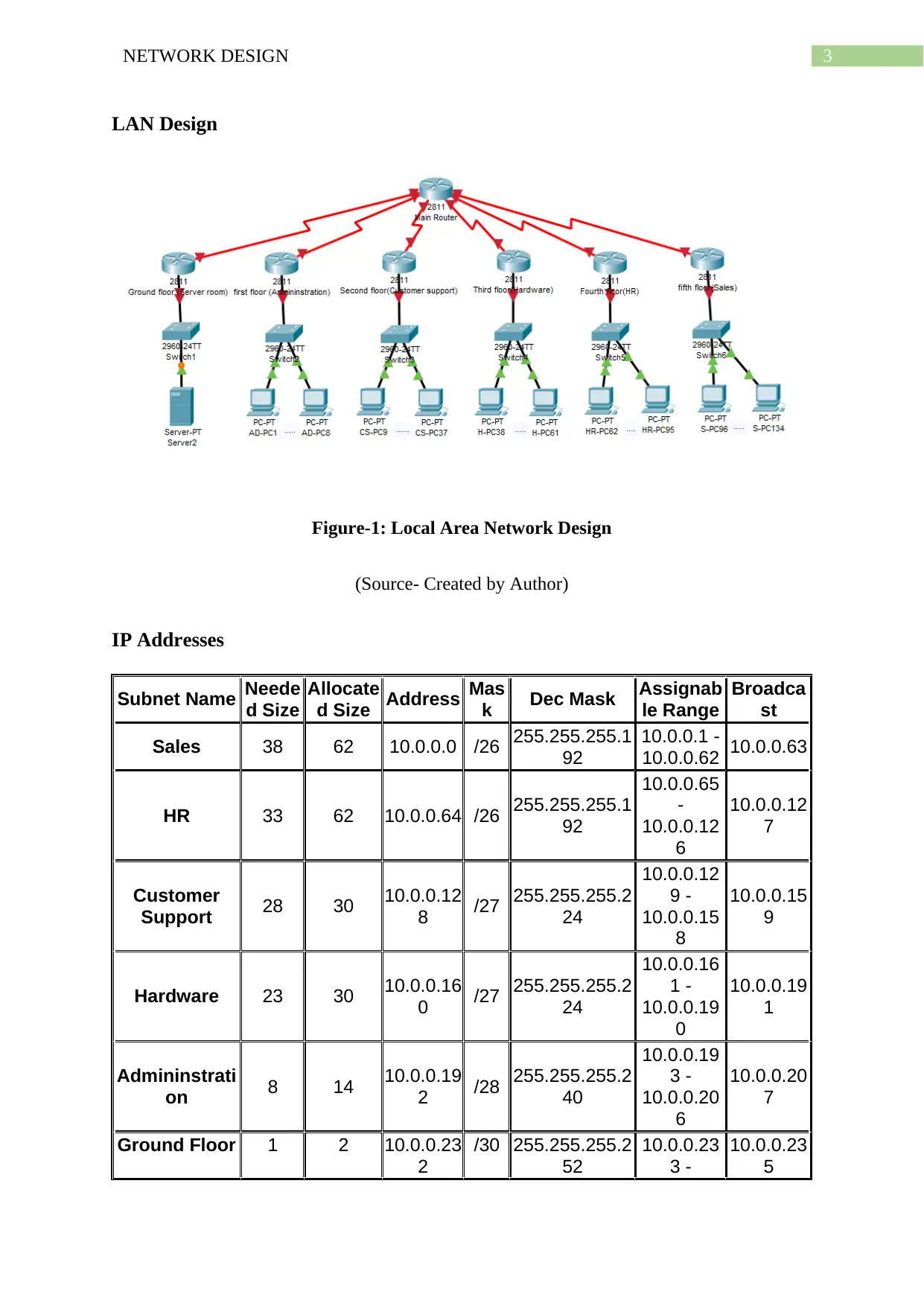
4NETWORK DESIGN 10.0.0.23 4 Description of the hardware The hardware that has been for the setting up of this local area network has been described below in brief (Lyuet al., 2016). These are, Every single department has been provided with a single router along with that of a switch dedicatedly serving every single floor of the five - floor building belonging to the Top Class Network (TCN) organization. The ground floor, which has been referred to as the server room has been provided with the server. This also consists of a separate switch. Each of the routers have been connected with that of the main router with the help of Serial DTE wires (Valizade, Rezaei and Orouji, 2015). Serial DTE cables have been utilized specifically for this connections since, these cables provision with a better shielding as well as an enhanced way of connection with much faster communication getting carried out. All of the routers have been connected to the switch before the switch again forms a specificconnectionwithalltheworkstationspresentwithinthedepartments separately. Connection of the routers to the switches and again the workstations to the switches have been done with the help of Copper Straight-through wires (Liao, Li and Chen, 2016). Copper straight-through wires have been used for an enhanced connection between the communication getting carried out within the switch and the workstations that are present within the network.
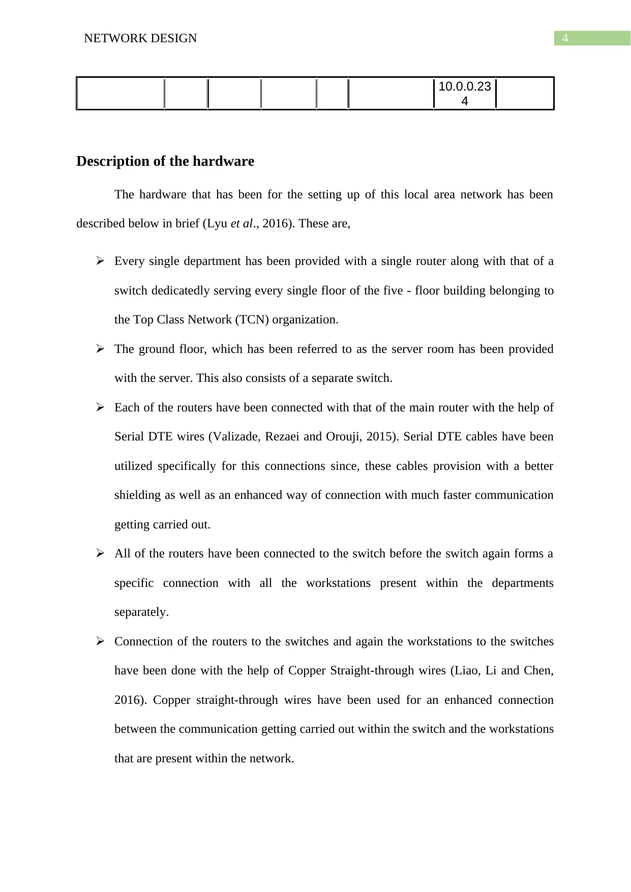
5NETWORK DESIGN The server present in the ground floor has been connected with the switch that has been provided to the first floor with the help of the same copper Straight-through wires. Conclusion As a conclusion to the above discussion, it can be stated that network diagram has been done taking into consideration the fact that shall make the working of the network the most efficient. The network topology has been chosen in accordance with the presence of the number of main router. Following this, the components of the network has been chosen along with the inclusion of the reason for which such components have been chosen as well as the number of each components. The LAN diagram has been given including all the components forming the network. Subnetting of the IP addresses has been in addition to the entire description of each and every software that has been utilized for the formation of the network.