NETWORK DESIGNING AND TROUBLESHOOT
Case study analysis on network design and troubleshooting, assessing principles, processes, business and technical requirements, network infrastructure planning and design, management and implementation strategies, vendor solutions, alternative methods and techniques, and troubleshooting and maintenance of complex networks.
Added on 2022-08-14
Network Designing and Troubleshoot
Name of the Student
Name of the University
Author’s Note

NETWORK DESIGNING AND TROUBLESHOOT
Table of Contents
Introduction......................................................................................................................................2
Knowledge and understanding........................................................................................................3
Application and Analysis.................................................................................................................4
Evaluation and Judgement...............................................................................................................4
Design and Implementation.............................................................................................................5
Testing and documentation............................................................................................................12
Conclusion.....................................................................................................................................15
Reference List................................................................................................................................16
Appendix A....................................................................................................................................19
NETWORK DESIGNING AND TROUBLESHOOT
Introduction
The report is created for speedfix.co.uk that have the need to deploy a network after
analysis of the current business scenario and separating each of the department by assigning
multiple VLANs. An analysis is made on the different network model that can be deployed and
the technologies and protocols that can be used for configuring the network. The functional and
nonfunctional needs of the network are evaluated for finding the relation between them with the
network equipment’s. The company have three department i.e. finance /HR, sales and engineers
and they are needed to be assigned with LAN. The network is needed to be designed such that
servers are installed in separate area and assigned to separate VLAN. A wireless network is also
required to be configured for connecting the wireless network and its access is needed to be
restricted for the other departments.
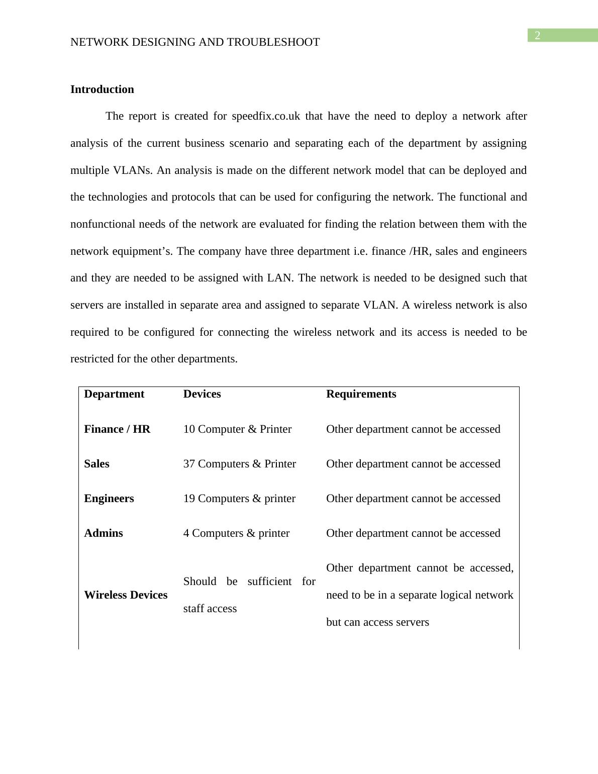
Department Devices Requirements
Finance / HR 10 Computer & Printer Other department cannot be accessed
Sales 37 Computers & Printer Other department cannot be accessed
Engineers 19 Computers & printer Other department cannot be accessed
Admins 4 Computers & printer Other department cannot be accessed
Wireless Devices
Should be sufficient for
staff access
Other department cannot be accessed,
need to be in a separate logical network
but can access servers
NETWORK DESIGNING AND TROUBLESHOOT
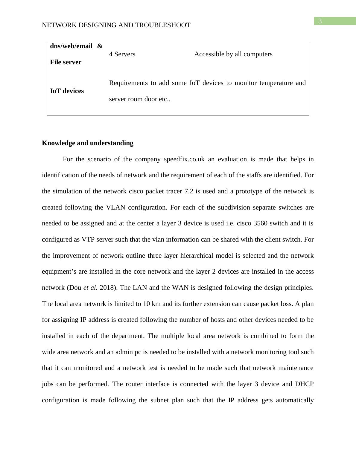
dns/web/email &
File server
4 Servers Accessible by all computers
IoT devices
Requirements to add some IoT devices to monitor temperature and
server room door etc..
Knowledge and understanding
For the scenario of the company speedfix.co.uk an evaluation is made that helps in
identification of the needs of network and the requirement of each of the staffs are identified. For
the simulation of the network cisco packet tracer 7.2 is used and a prototype of the network is
created following the VLAN configuration. For each of the subdivision separate switches are
needed to be assigned and at the center a layer 3 device is used i.e. cisco 3560 switch and it is
configured as VTP server such that the vlan information can be shared with the client switch. For
the improvement of network outline three layer hierarchical model is selected and the network
equipment’s are installed in the core network and the layer 2 devices are installed in the access
network (Dou et al. 2018). The LAN and the WAN is designed following the design principles.
The local area network is limited to 10 km and its further extension can cause packet loss. A plan
for assigning IP address is created following the number of hosts and other devices needed to be
installed in each of the department. The multiple local area network is combined to form the
wide area network and an admin pc is needed to be installed with a network monitoring tool such
that it can monitored and a network test is needed to be made such that network maintenance
jobs can be performed. The router interface is connected with the layer 3 device and DHCP
configuration is made following the subnet plan such that the IP address gets automatically
NETWORK DESIGNING AND TROUBLESHOOT
assigned (Hasan and Mahmood 2019). The configuration of the network device with DHCP
helps in increasing the scalability of the network and it can be configured at the central device
for implementation of the changes.
Application and Analysis
The network is needed to be configured for connecting IoT devices and monitoring the
environment of the server rooms for maintaining an optimal environment. A private IP address
of 192.168.168.0/24 is used for the wired LAN and 10.10.10.0/24 is used for the wireless
network. A network diagram is created with the description of analysis and appropriate subnet
address is created for the configuration of the network. A network model is proposed that would
help in selection of protocol and technology and develop the network following the company
needs (Ortiz 2016). An analysis is also made on the security needs and applied for isolating the
access of each of the department and testing documentation is created for the configuration and
network device and verification of the configuration.
The layer three switch is used for allowing VTP server configuration and allowing the
layer 2 devices configured as client to automatically fetch the VLAN information (Talavera and
Santisteban 2015). The router manages the access of the users of different VLAN to reach the
server and can be configured with access control list for enforcing centralized management and
restrict an IP to access the server.
Evaluation and Judgement
There are multiple departments in the speedfix.co.uk company that is Finance/HR, Sales,
Engineers, Admins. Vlans are needed to be created for the department and the server, wireless
and iot devices network and it is needed to be assigned with a name and number for configuring
NETWORK DESIGNING AND TROUBLESHOOT
the network. The VLAN can be used as a separation for the different departments and it helps in
offering the user to secure and management of network flow and improve the network scalability
(Ahamed 2018). Local area network is used for connecting the computers and the virtual LANs
can be used for connecting with the physical network without the need of multiple cabling set
and network device. The VLAN can help the network administrator grouping the host even if the
network devices are not connected with the same switch directly. VLAN can help in creating a
simple network design and deploy the network for reducing congestion and collision in the
network (Gao et al. 2017). The network can be subdivided into VLANs and configuring the
network equipment’s and partition the network as the physical port.
For the configuration of the layer 3 switch VTP server configuration is analyzed and a
configuration is made for the switch and configuring the VTP domain and named as AAA. The
main layer 3 switch connected with the router interface is configured as VTP server and the
switch installed for providing service to the different departments are configured as VTP client
(Xu et al. 2015). The switchport are configured with trunk for sharing the VLAN information
and allow the host to be assigned with specific IP address created for that dhcp pool.
End of preview
Want to access all the pages? Upload your documents or become a member.