Network Topology and Server Setup
VerifiedAdded on 2023/01/05
|18
|1165
|8
AI Summary
This document provides a detailed guide on network topology and server setup. It covers the design and configuration of routers, switches, servers, and PCs. It also explains the IP addressing scheme and the setup of web server, DNS server, DHCP, and firewall. Additionally, it discusses network simulation and emulation tools.
Contribute Materials
Your contribution can guide someone’s learning journey. Share your
documents today.

Running head: NETWORK TOPOLOGY AND SERVER SETUP
Network Topology and Server Setup
Student Name
University Name
Note by the Author
Network Topology and Server Setup
Student Name
University Name
Note by the Author
Secure Best Marks with AI Grader
Need help grading? Try our AI Grader for instant feedback on your assignments.
1NETWORK TOPOLOGY AND SERVER SETUP
Task 1: Network Design and Setup
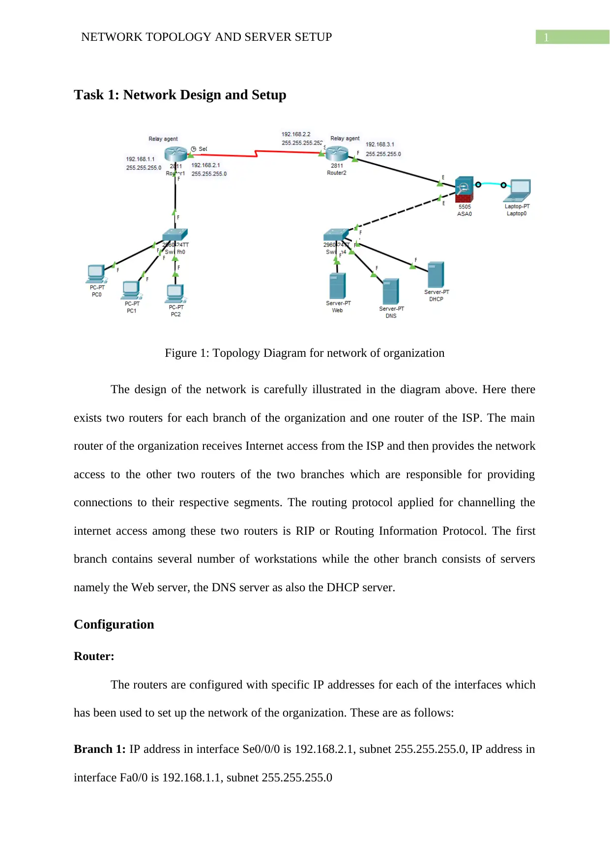
Figure 1: Topology Diagram for network of organization
The design of the network is carefully illustrated in the diagram above. Here there
exists two routers for each branch of the organization and one router of the ISP. The main
router of the organization receives Internet access from the ISP and then provides the network
access to the other two routers of the two branches which are responsible for providing
connections to their respective segments. The routing protocol applied for channelling the
internet access among these two routers is RIP or Routing Information Protocol. The first
branch contains several number of workstations while the other branch consists of servers
namely the Web server, the DNS server as also the DHCP server.
Configuration
Router:
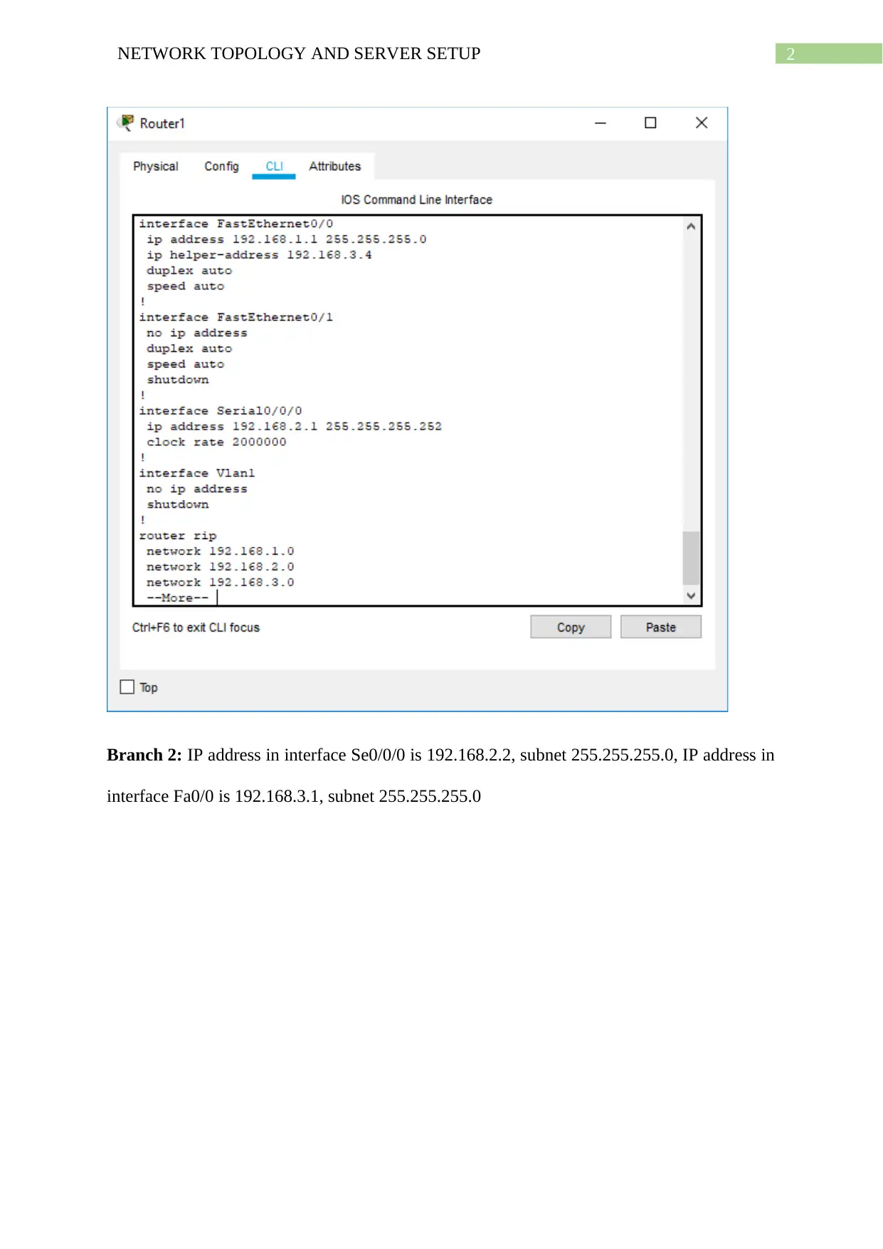
The routers are configured with specific IP addresses for each of the interfaces which
has been used to set up the network of the organization. These are as follows:
Branch 1: IP address in interface Se0/0/0 is 192.168.2.1, subnet 255.255.255.0, IP address in
interface Fa0/0 is 192.168.1.1, subnet 255.255.255.0
2NETWORK TOPOLOGY AND SERVER SETUP
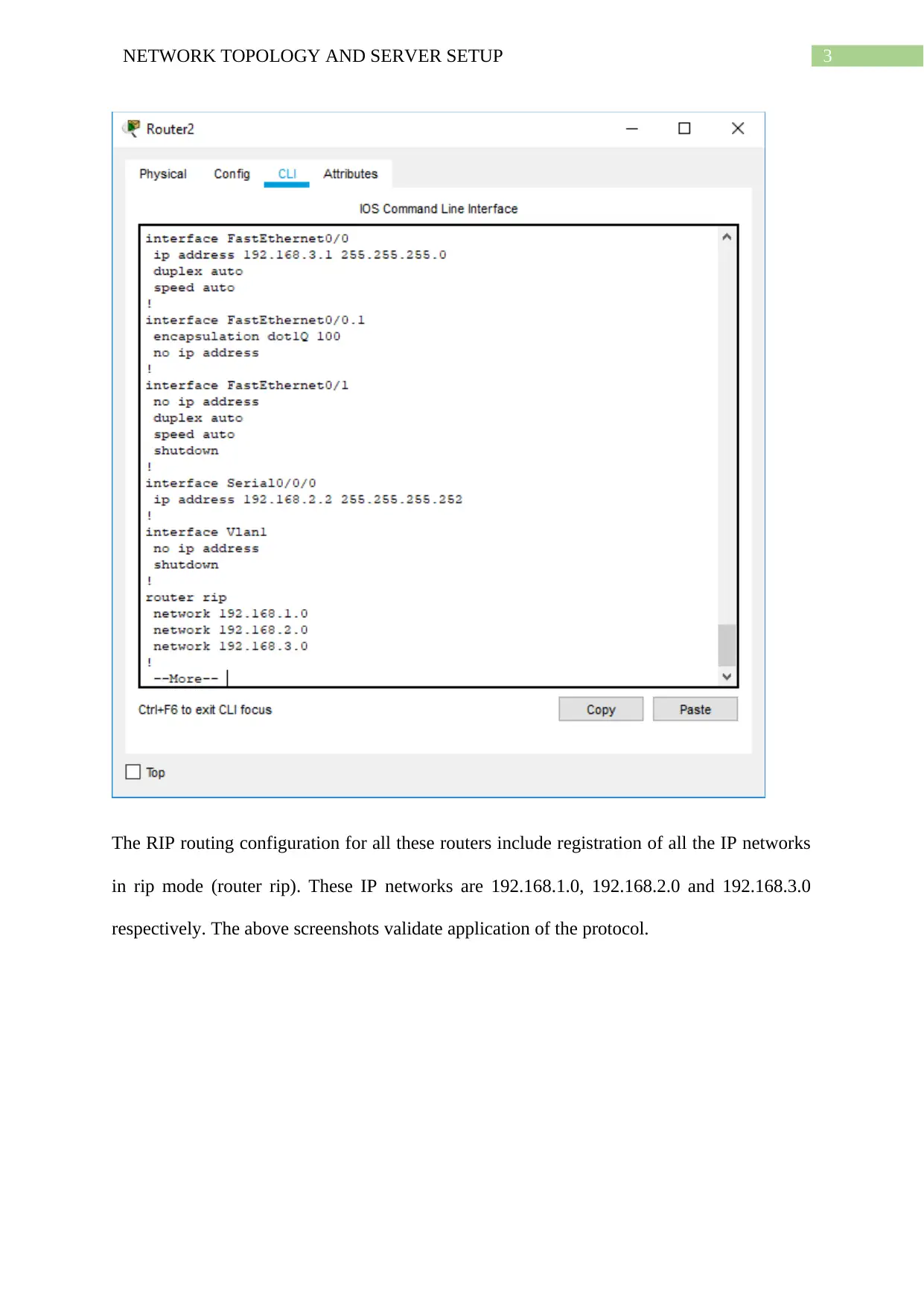
Branch 2: IP address in interface Se0/0/0 is 192.168.2.2, subnet 255.255.255.0, IP address in
interface Fa0/0 is 192.168.3.1, subnet 255.255.255.0
Branch 2: IP address in interface Se0/0/0 is 192.168.2.2, subnet 255.255.255.0, IP address in
interface Fa0/0 is 192.168.3.1, subnet 255.255.255.0
3NETWORK TOPOLOGY AND SERVER SETUP
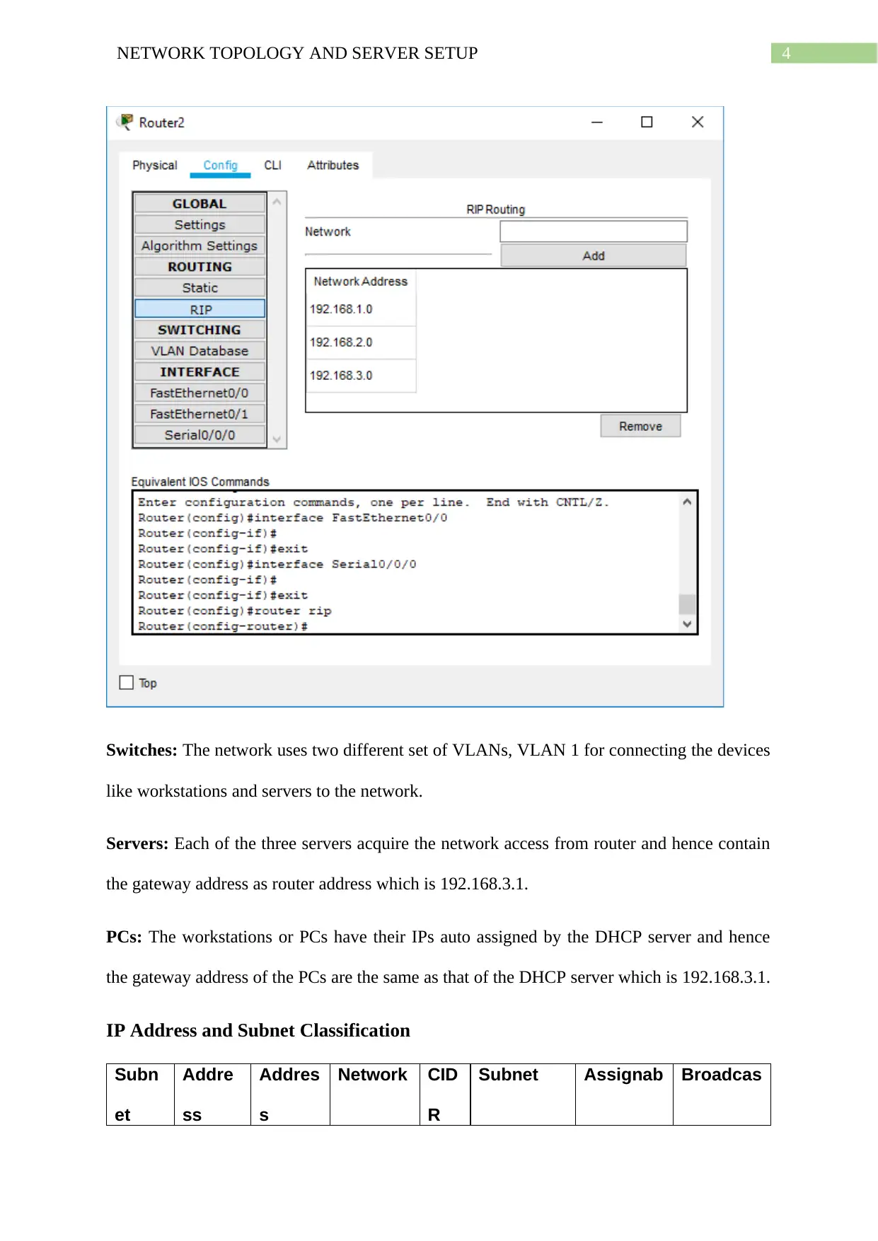
The RIP routing configuration for all these routers include registration of all the IP networks
in rip mode (router rip). These IP networks are 192.168.1.0, 192.168.2.0 and 192.168.3.0
respectively. The above screenshots validate application of the protocol.
The RIP routing configuration for all these routers include registration of all the IP networks
in rip mode (router rip). These IP networks are 192.168.1.0, 192.168.2.0 and 192.168.3.0
respectively. The above screenshots validate application of the protocol.
Secure Best Marks with AI Grader
Need help grading? Try our AI Grader for instant feedback on your assignments.
4NETWORK TOPOLOGY AND SERVER SETUP
Switches: The network uses two different set of VLANs, VLAN 1 for connecting the devices
like workstations and servers to the network.
Servers: Each of the three servers acquire the network access from router and hence contain
the gateway address as router address which is 192.168.3.1.
PCs: The workstations or PCs have their IPs auto assigned by the DHCP server and hence
the gateway address of the PCs are the same as that of the DHCP server which is 192.168.3.1.
IP Address and Subnet Classification
Subn
et
Addre
ss
Addres
s
Network CID
R
Subnet Assignab Broadcas
5NETWORK TOPOLOGY AND SERVER SETUP
Nami
ng
Space
Requir
ed
Space
Allocat
ed
Address
Mas
k
Mask le IPs t Address
Branc
h1
3 254
192.168.
1.0
/26
255.255.25
5.0
192.168.1
.1 -
192.168.1
.62
192.168.1
.63
Branc
h2
3 254
192.168.
3.0
/26
255.255.25
5.0
192.168.2
.1 -
192.168.2
.62
192.168.2
.63
B1-B2 2 2
192.168.
2.0
/30
255.255.25
5.0
192.168.2
.1 –
192.168.2
.2
192.168.2
.2
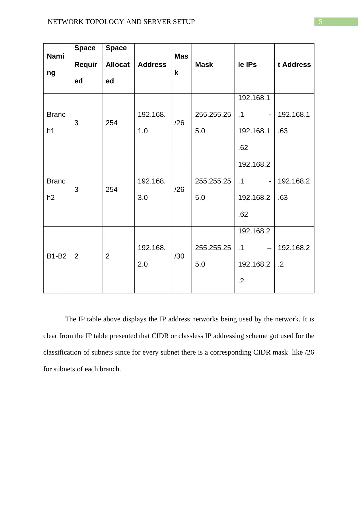
The IP table above displays the IP address networks being used by the network. It is
clear from the IP table presented that CIDR or classless IP addressing scheme got used for the
classification of subnets since for every subnet there is a corresponding CIDR mask like /26
for subnets of each branch.
6NETWORK TOPOLOGY AND SERVER SETUP
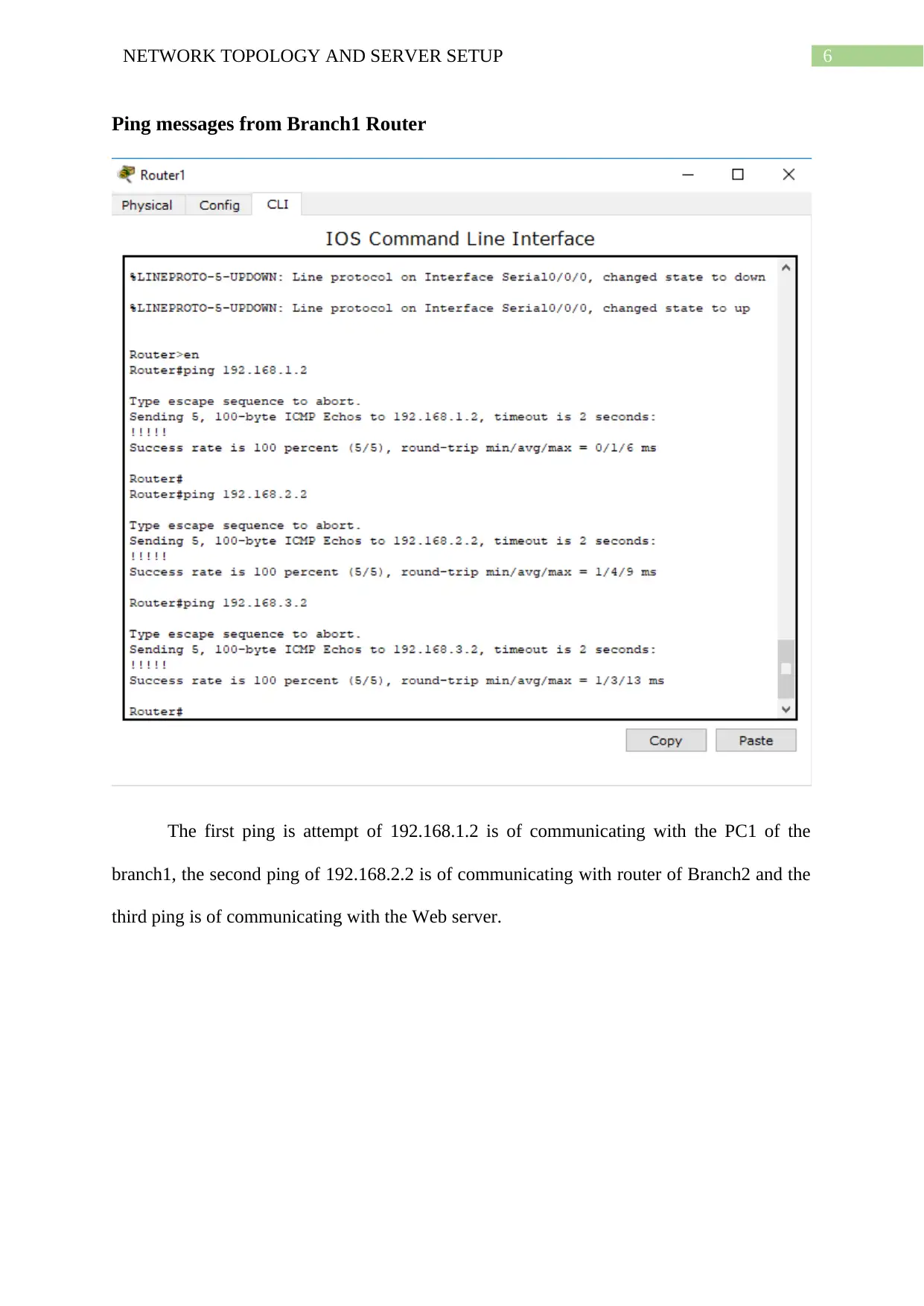
Ping messages from Branch1 Router
The first ping is attempt of 192.168.1.2 is of communicating with the PC1 of the
branch1, the second ping of 192.168.2.2 is of communicating with router of Branch2 and the
third ping is of communicating with the Web server.
Ping messages from Branch1 Router
The first ping is attempt of 192.168.1.2 is of communicating with the PC1 of the
branch1, the second ping of 192.168.2.2 is of communicating with router of Branch2 and the
third ping is of communicating with the Web server.
Paraphrase This Document
Need a fresh take? Get an instant paraphrase of this document with our AI Paraphraser
7NETWORK TOPOLOGY AND SERVER SETUP
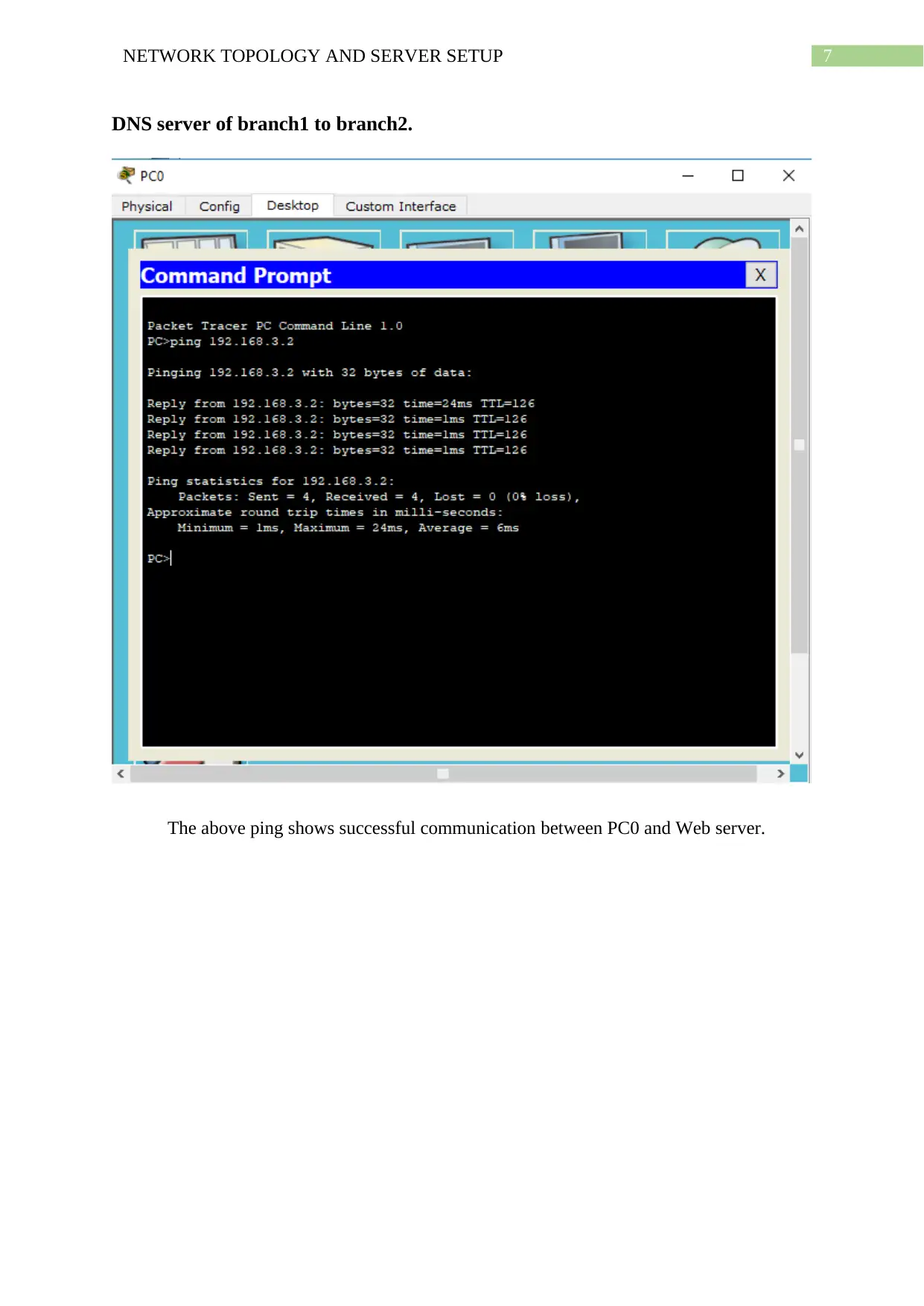
DNS server of branch1 to branch2.
The above ping shows successful communication between PC0 and Web server.
DNS server of branch1 to branch2.
The above ping shows successful communication between PC0 and Web server.
8NETWORK TOPOLOGY AND SERVER SETUP
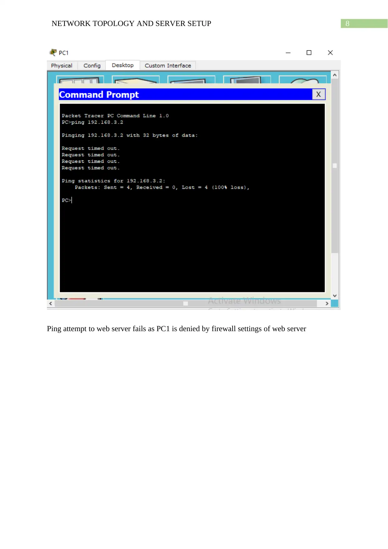
Ping attempt to web server fails as PC1 is denied by firewall settings of web server
Ping attempt to web server fails as PC1 is denied by firewall settings of web server
9NETWORK TOPOLOGY AND SERVER SETUP
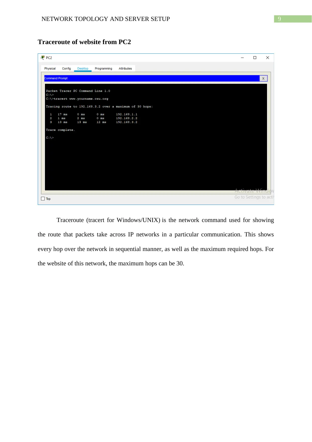
Traceroute of website from PC2
Traceroute (tracert for Windows/UNIX) is the network command used for showing
the route that packets take across IP networks in a particular communication. This shows
every hop over the network in sequential manner, as well as the maximum required hops. For
the website of this network, the maximum hops can be 30.
Secure Best Marks with AI Grader
Need help grading? Try our AI Grader for instant feedback on your assignments.
10NETWORK TOPOLOGY AND SERVER SETUP
Task 2: Configuration of Servers – Web Server, DNS Server, DHCP,
Firewall
Web Server
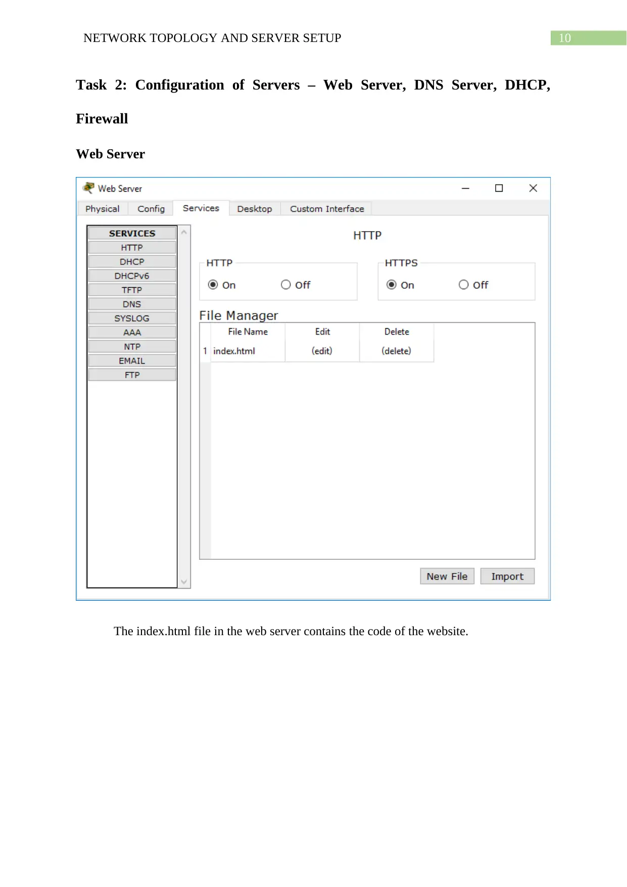
The index.html file in the web server contains the code of the website.
Task 2: Configuration of Servers – Web Server, DNS Server, DHCP,
Firewall
Web Server
The index.html file in the web server contains the code of the website.
11NETWORK TOPOLOGY AND SERVER SETUP
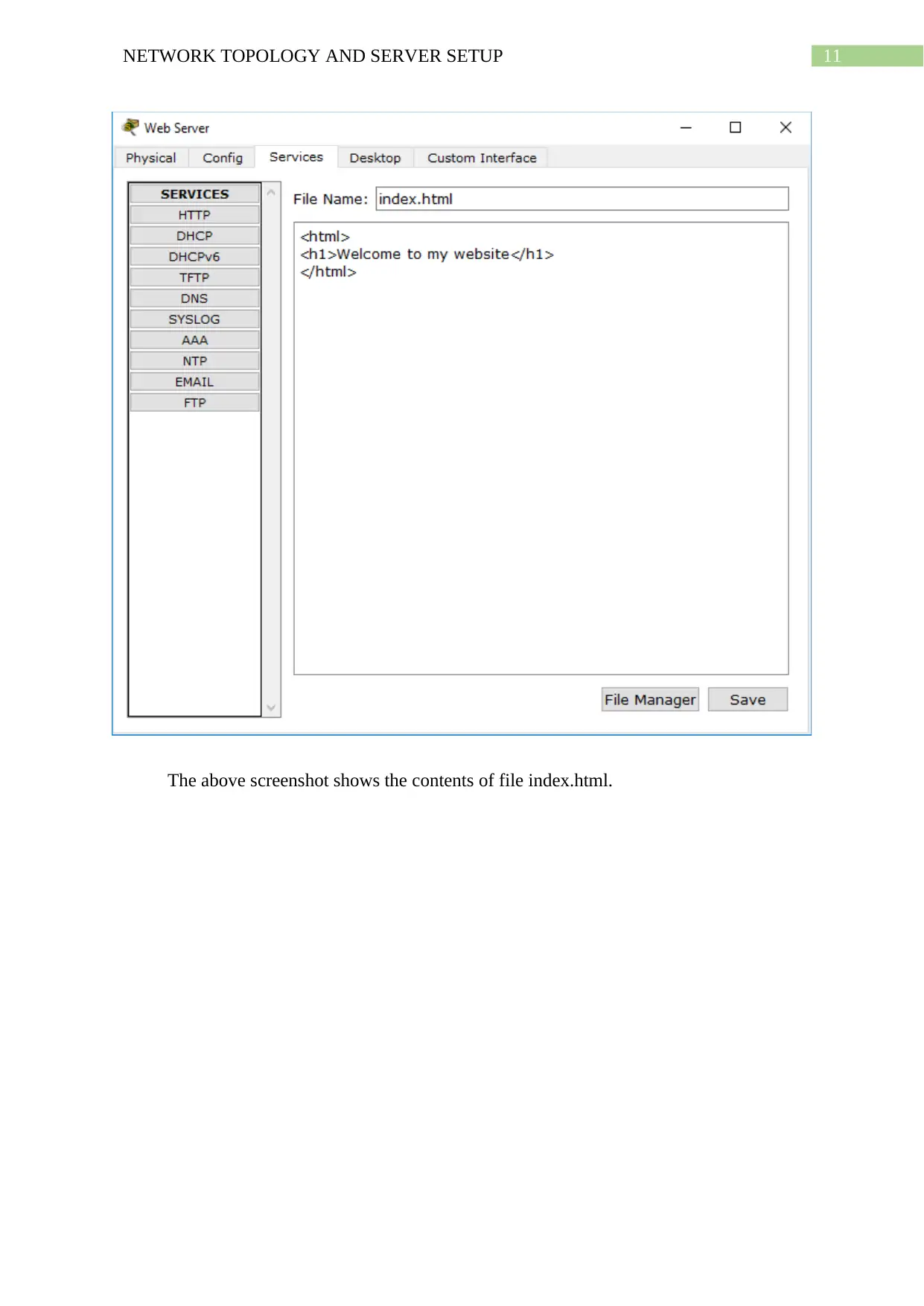
The above screenshot shows the contents of file index.html.
The above screenshot shows the contents of file index.html.
12NETWORK TOPOLOGY AND SERVER SETUP
Firewall
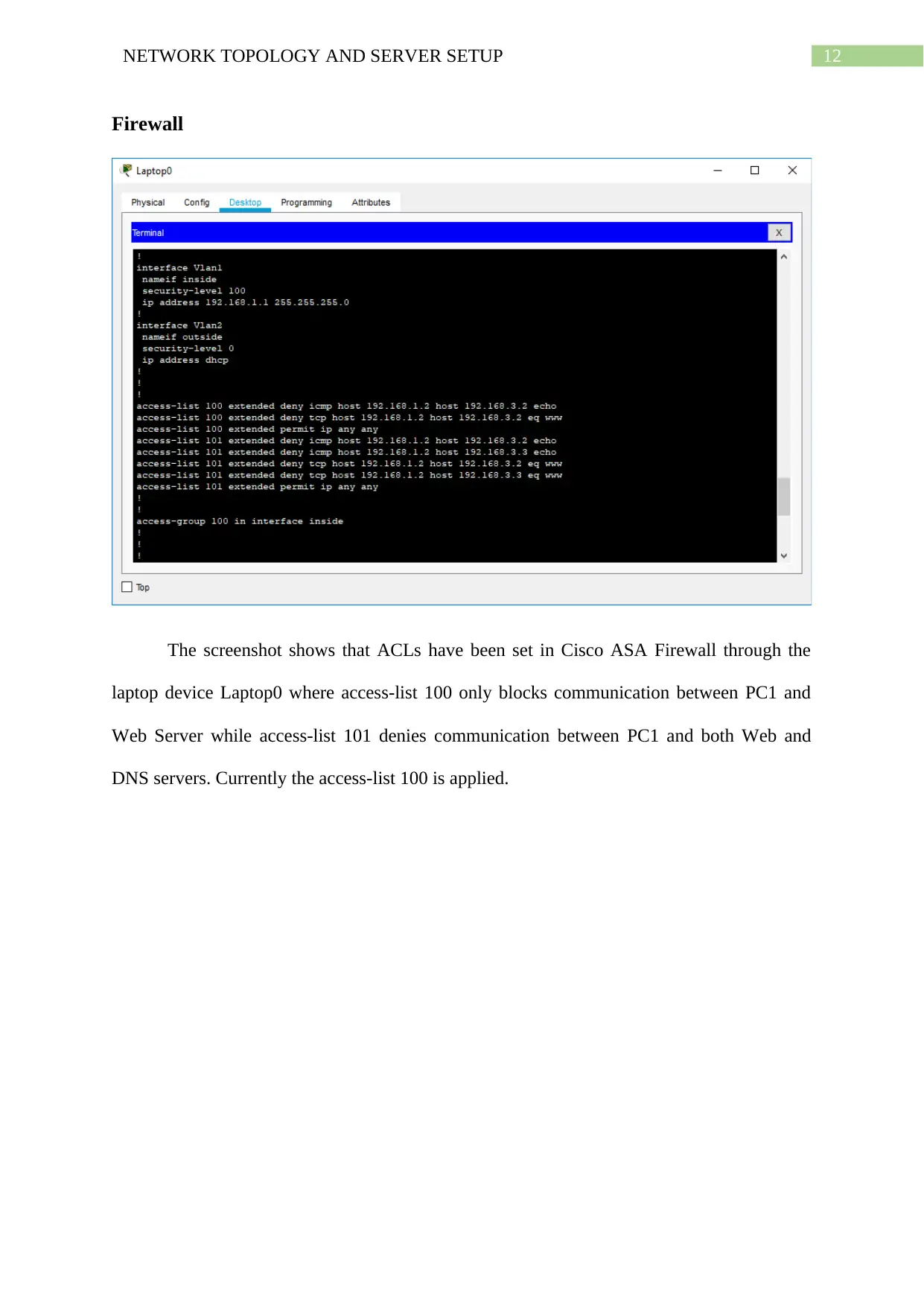
The screenshot shows that ACLs have been set in Cisco ASA Firewall through the
laptop device Laptop0 where access-list 100 only blocks communication between PC1 and
Web Server while access-list 101 denies communication between PC1 and both Web and
DNS servers. Currently the access-list 100 is applied.
Paraphrase This Document
Need a fresh take? Get an instant paraphrase of this document with our AI Paraphraser
13NETWORK TOPOLOGY AND SERVER SETUP
DNS Server
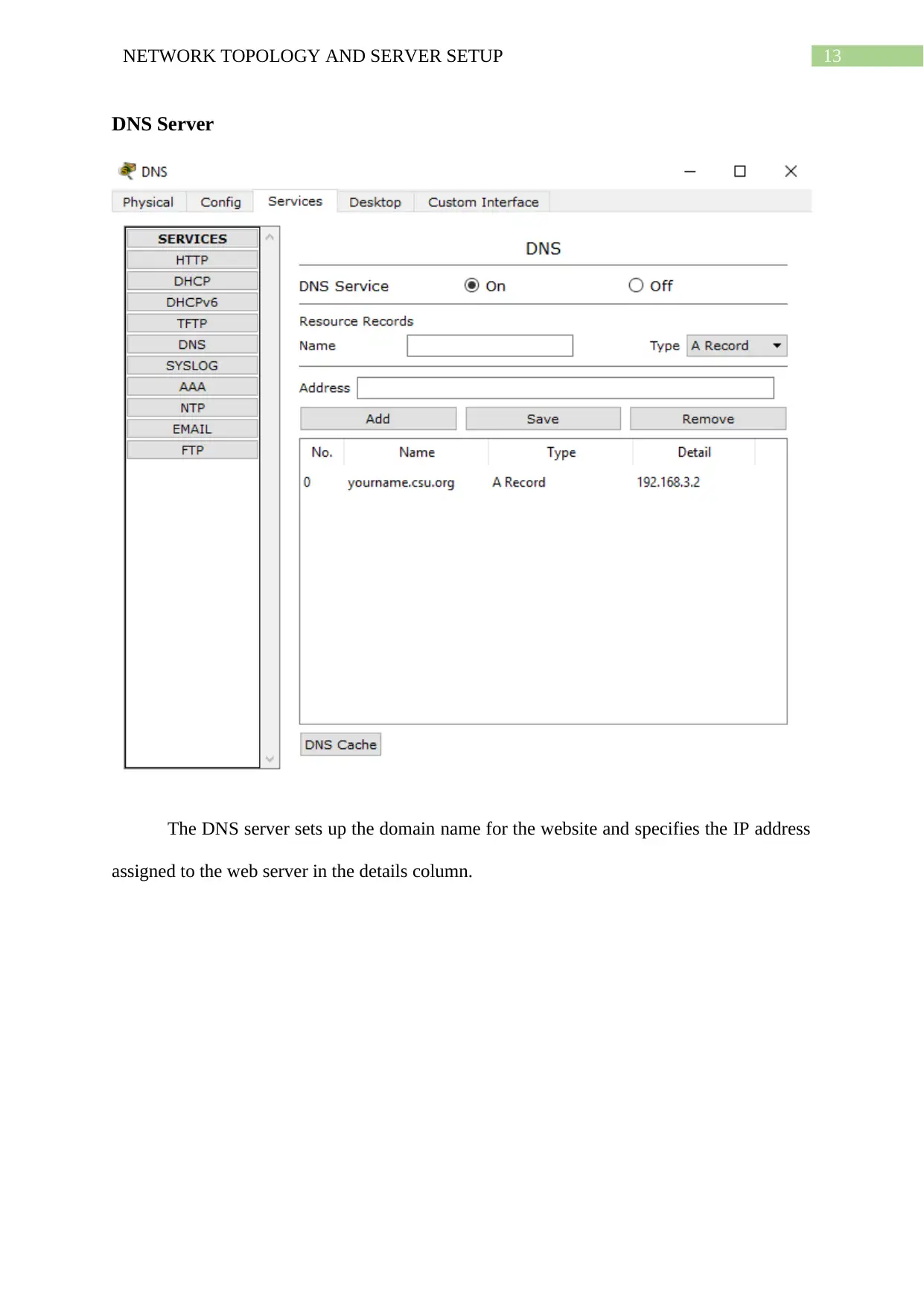
The DNS server sets up the domain name for the website and specifies the IP address
assigned to the web server in the details column.
DNS Server
The DNS server sets up the domain name for the website and specifies the IP address
assigned to the web server in the details column.
14NETWORK TOPOLOGY AND SERVER SETUP
DHCP Server
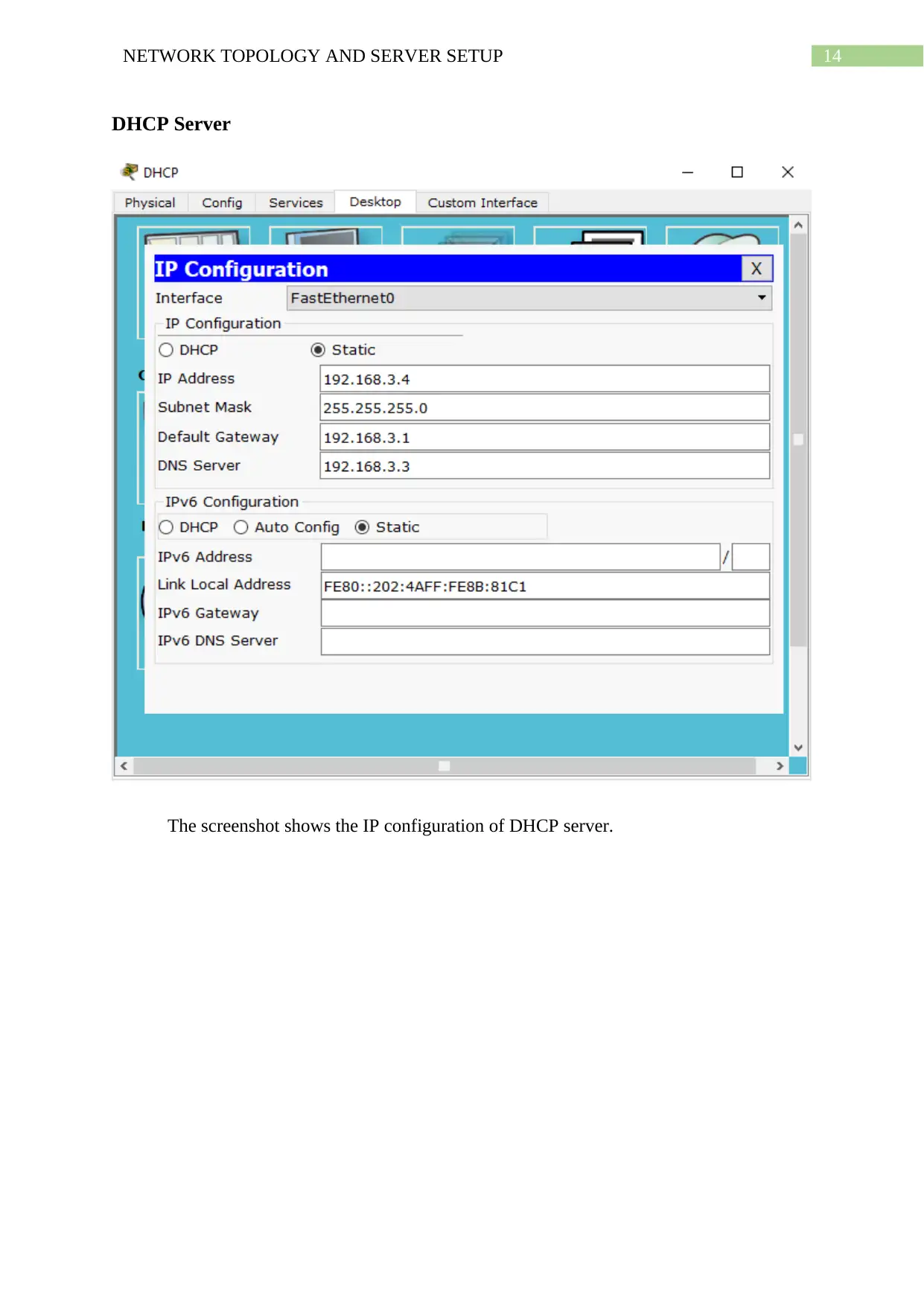
The screenshot shows the IP configuration of DHCP server.
DHCP Server
The screenshot shows the IP configuration of DHCP server.
15NETWORK TOPOLOGY AND SERVER SETUP
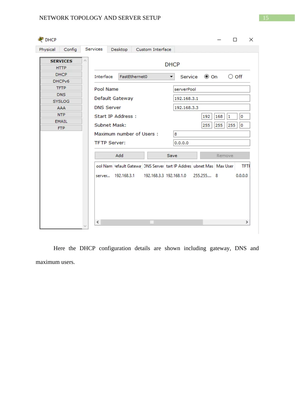
Here the DHCP configuration details are shown including gateway, DNS and
maximum users.
Here the DHCP configuration details are shown including gateway, DNS and
maximum users.
Secure Best Marks with AI Grader
Need help grading? Try our AI Grader for instant feedback on your assignments.
16NETWORK TOPOLOGY AND SERVER SETUP
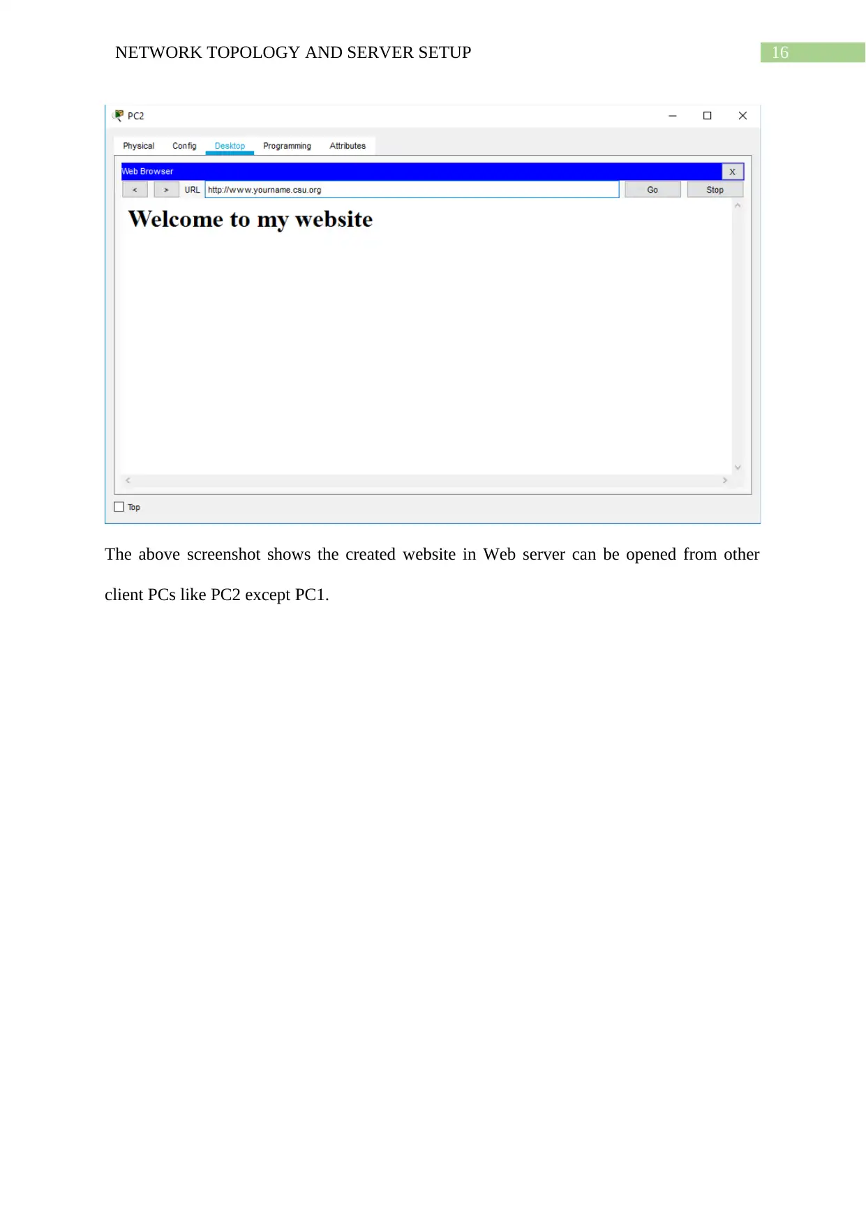
The above screenshot shows the created website in Web server can be opened from other
client PCs like PC2 except PC1.
The above screenshot shows the created website in Web server can be opened from other
client PCs like PC2 except PC1.
17NETWORK TOPOLOGY AND SERVER SETUP
Bibliography
Airi, P., & Anderson, P. K. (2017). Cisco Packet Tracer as a teaching and learning tool for
computer networks in DWU. Contemporary PNG Studies, 26, 88.
Al-Ani, D. R., & Al-Ani, A. R. (2018). The performance of IPv4 and IPv6 in terms of
Routing Protocols using GNS 3 Simulator. Procedia computer science, 130, 1051-
1056.
Arote, P., & Arya, K. V. (2015, January). Detection and prevention against ARP poisoning
attack using modified ICMP and voting. In 2015 International Conference on
Computational Intelligence and Networks (pp. 136-141). IEEE.
Chou, T. S., Baker, S., & Vega-Herrera, M. (2016, June). A comparison of network
simulation and emulation virtualization tools. In Proc. ASEE Annu. Conf. Expo. (pp.
1-9).
Noor, N. M. M., Yayao, N., & Sulaiman, S. (2018). Effectiveness Of Using Cisco Packet
Tracer As a Learning Tool: A Case Study Of Routing Protocol. Computer
software, 514, 689-9.
Shirmarz, A., & Sabaei, M. (2016). Evaluation and comparison of binary trie base IP lookup
algorithms with real edge router IP prefix dataset. Evaluation, 7(6).
1 out of 18
Related Documents
Your All-in-One AI-Powered Toolkit for Academic Success.
+13062052269
info@desklib.com
Available 24*7 on WhatsApp / Email
![[object Object]](/_next/static/media/star-bottom.7253800d.svg)
Unlock your academic potential
© 2024 | Zucol Services PVT LTD | All rights reserved.


