ICTNWK517 Diploma Project: Neutronics Enterprise Network Design
VerifiedAdded on 2023/06/11
|11
|1674
|131
Report
AI Summary
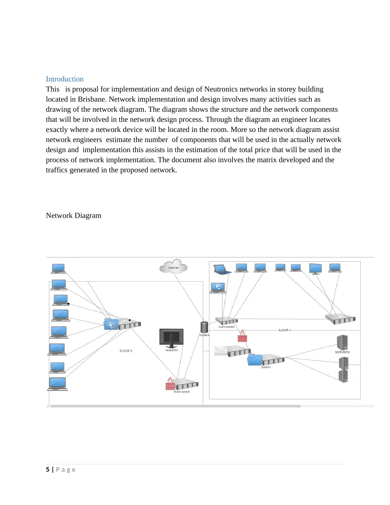
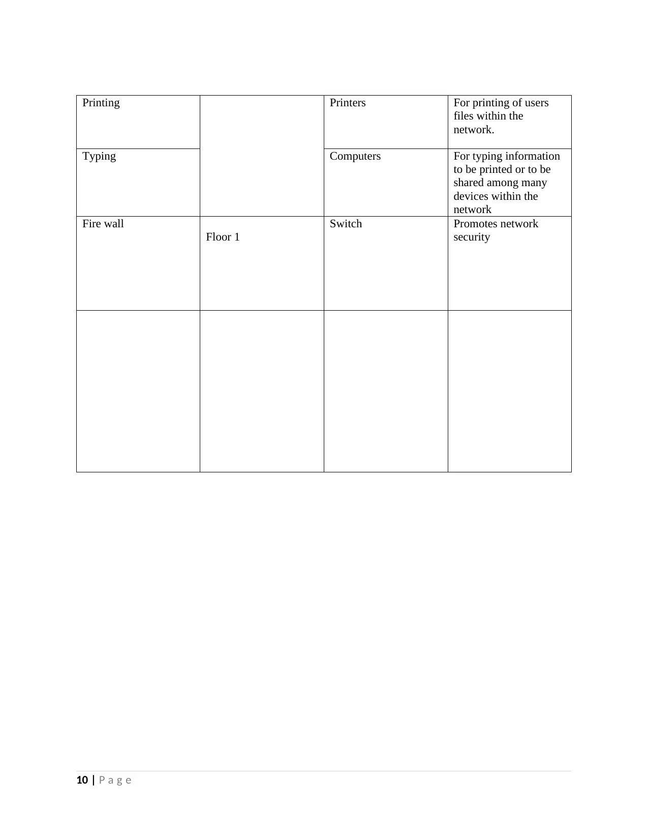
This document details the implementation and design of a Wide Area Network (WAN) for Neutronics Enterprise, focusing on their Brisbane office. It includes a network diagram illustrating the proposed layout with components like PCs, network switches, routers, cables, and firewalls. The design incorporates a cloud internet connection to facilitate communication between offices in different cities, aiming to reduce costs through shared resources. The report specifies the use of broadband routers, multilayer switches for efficient data transfer, and three servers (file, database, and domain) to manage data storage, requests, and user authentication. A star topology is implemented for its cost-effectiveness, ease of troubleshooting, and high-speed data transfer. Traffic estimation and cost analysis are provided, along with a functional matrix outlining resource allocation and network security measures.

1 out of 11
Related Documents


Your All-in-One AI-Powered Toolkit for Academic Success.
+13062052269
info@desklib.com
Available 24*7 on WhatsApp / Email
![[object Object]](/_next/static/media/star-bottom.7253800d.svg)
Copyright © 2020–2026 A2Z Services. All Rights Reserved. Developed and managed by ZUCOL.