MITS5002 - System Specification and Design Document for VIT Library
VerifiedAdded on 2023/06/03
|21
|2836
|213
Report
AI Summary
This document presents a comprehensive system and design specification for a library management system intended for use at the Victoria Institute of Technology (VIT). It includes an executive summary, system description, scope definition, and feasibility analysis covering technical, economic, and operational aspects. The document details both functional and non-functional requirements, constraints, and use cases with diagrams and descriptions. Furthermore, it provides an architectural design, hardware specifications, class diagrams, interface designs with wireframe diagrams, business process models, sequence diagrams, collaboration diagrams, and state diagrams. This complete overview offers a structured approach to developing an efficient and user-friendly library management system.
System and Design Document 1
Specification and Design Document
Name
Institution
Date
Specification and Design Document
Name
Institution
Date
Paraphrase This Document
Need a fresh take? Get an instant paraphrase of this document with our AI Paraphraser
System and Design Document 2
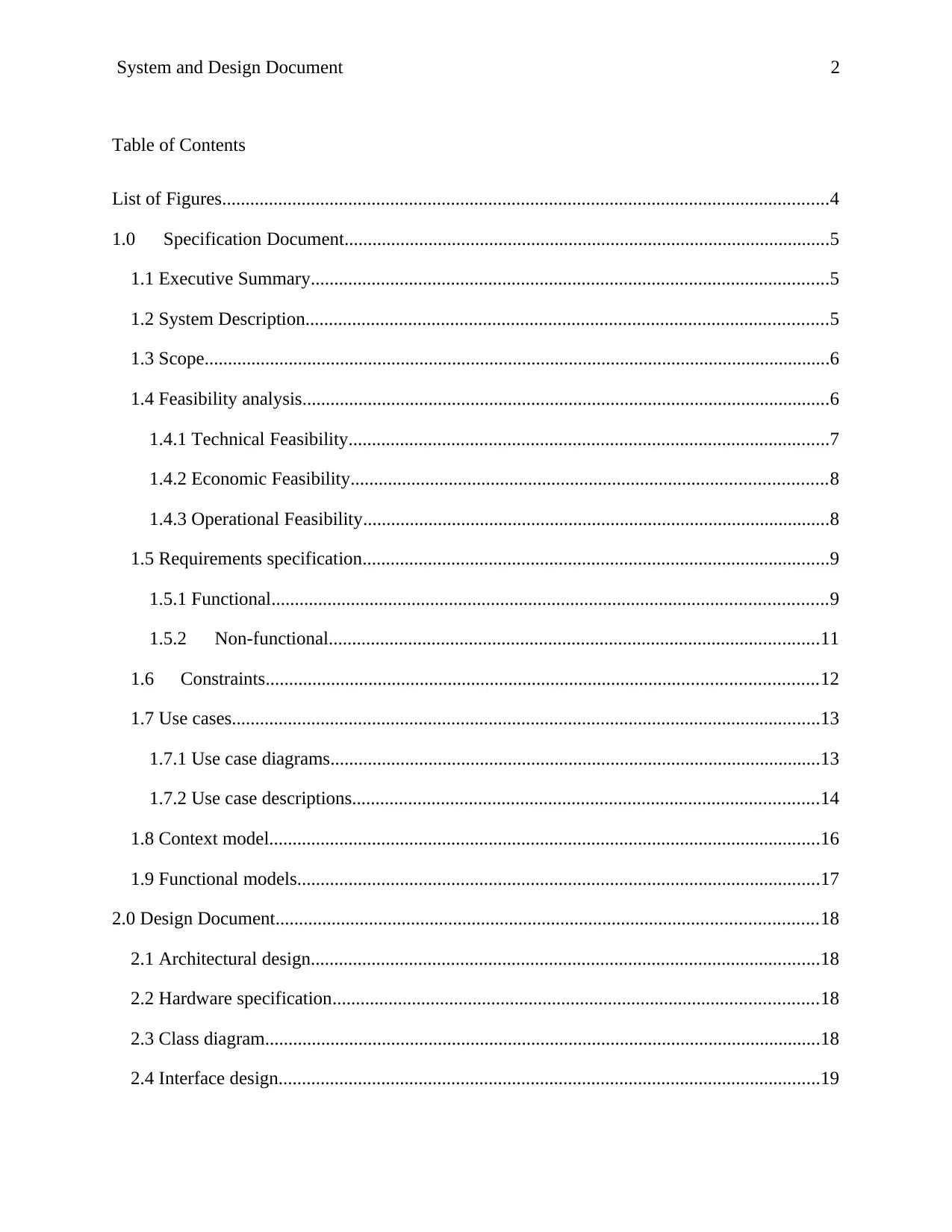
Table of Contents
List of Figures..................................................................................................................................4
1.0 Specification Document........................................................................................................5
1.1 Executive Summary...............................................................................................................5
1.2 System Description................................................................................................................5
1.3 Scope......................................................................................................................................6
1.4 Feasibility analysis.................................................................................................................6
1.4.1 Technical Feasibility.......................................................................................................7
1.4.2 Economic Feasibility......................................................................................................8
1.4.3 Operational Feasibility....................................................................................................8
1.5 Requirements specification....................................................................................................9
1.5.1 Functional.......................................................................................................................9
1.5.2 Non-functional.........................................................................................................11
1.6 Constraints......................................................................................................................12
1.7 Use cases..............................................................................................................................13
1.7.1 Use case diagrams.........................................................................................................13
1.7.2 Use case descriptions....................................................................................................14
1.8 Context model......................................................................................................................16
1.9 Functional models................................................................................................................17
2.0 Design Document....................................................................................................................18
2.1 Architectural design.............................................................................................................18
2.2 Hardware specification........................................................................................................18
2.3 Class diagram.......................................................................................................................18
2.4 Interface design....................................................................................................................19
Specification and Design Document 3
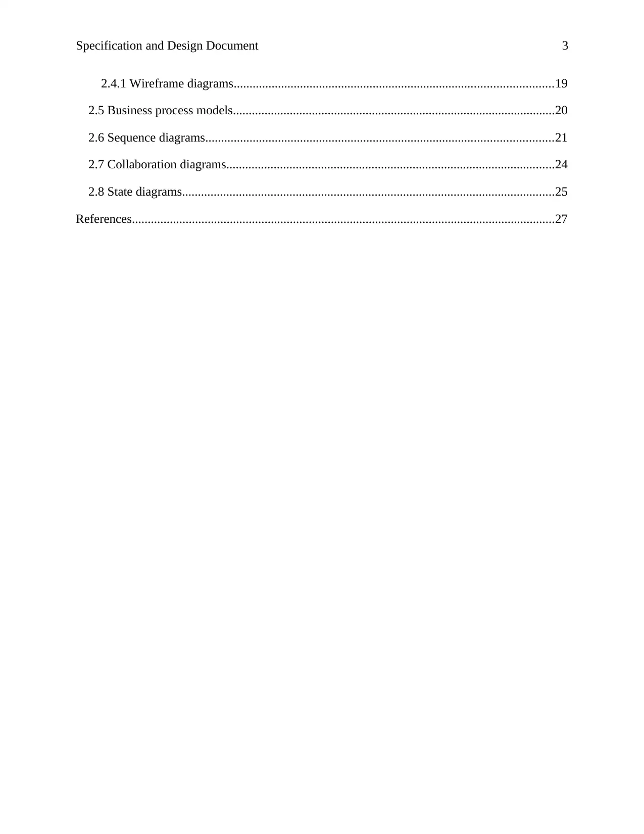
2.4.1 Wireframe diagrams.....................................................................................................19
2.5 Business process models......................................................................................................20
2.6 Sequence diagrams..............................................................................................................21
2.7 Collaboration diagrams........................................................................................................24
2.8 State diagrams......................................................................................................................25
References......................................................................................................................................27
⊘ This is a preview!⊘
Do you want full access?
Subscribe today to unlock all pages.

Trusted by 1+ million students worldwide
Specification and Design Document 4
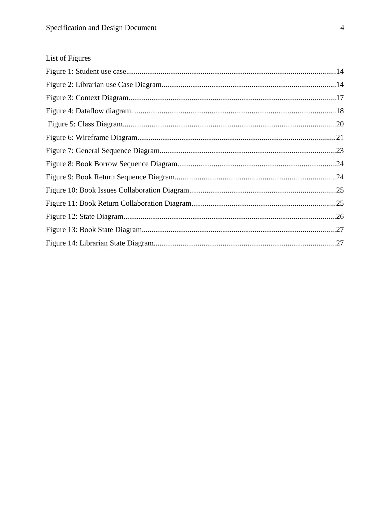
List of Figures
Figure 1: Student use case.............................................................................................................14
Figure 2: Librarian use Case Diagram...........................................................................................14
Figure 3: Context Diagram............................................................................................................17
Figure 4: Dataflow diagram...........................................................................................................18
Figure 5: Class Diagram...............................................................................................................20
Figure 6: Wireframe Diagram.......................................................................................................21
Figure 7: General Sequence Diagram............................................................................................23
Figure 8: Book Borrow Sequence Diagram...................................................................................24
Figure 9: Book Return Sequence Diagram....................................................................................24
Figure 10: Book Issues Collaboration Diagram............................................................................25
Figure 11: Book Return Collaboration Diagram...........................................................................25
Figure 12: State Diagram...............................................................................................................26
Figure 13: Book State Diagram.....................................................................................................27
Figure 14: Librarian State Diagram...............................................................................................27
Paraphrase This Document
Need a fresh take? Get an instant paraphrase of this document with our AI Paraphraser
Specification and Design Document 5
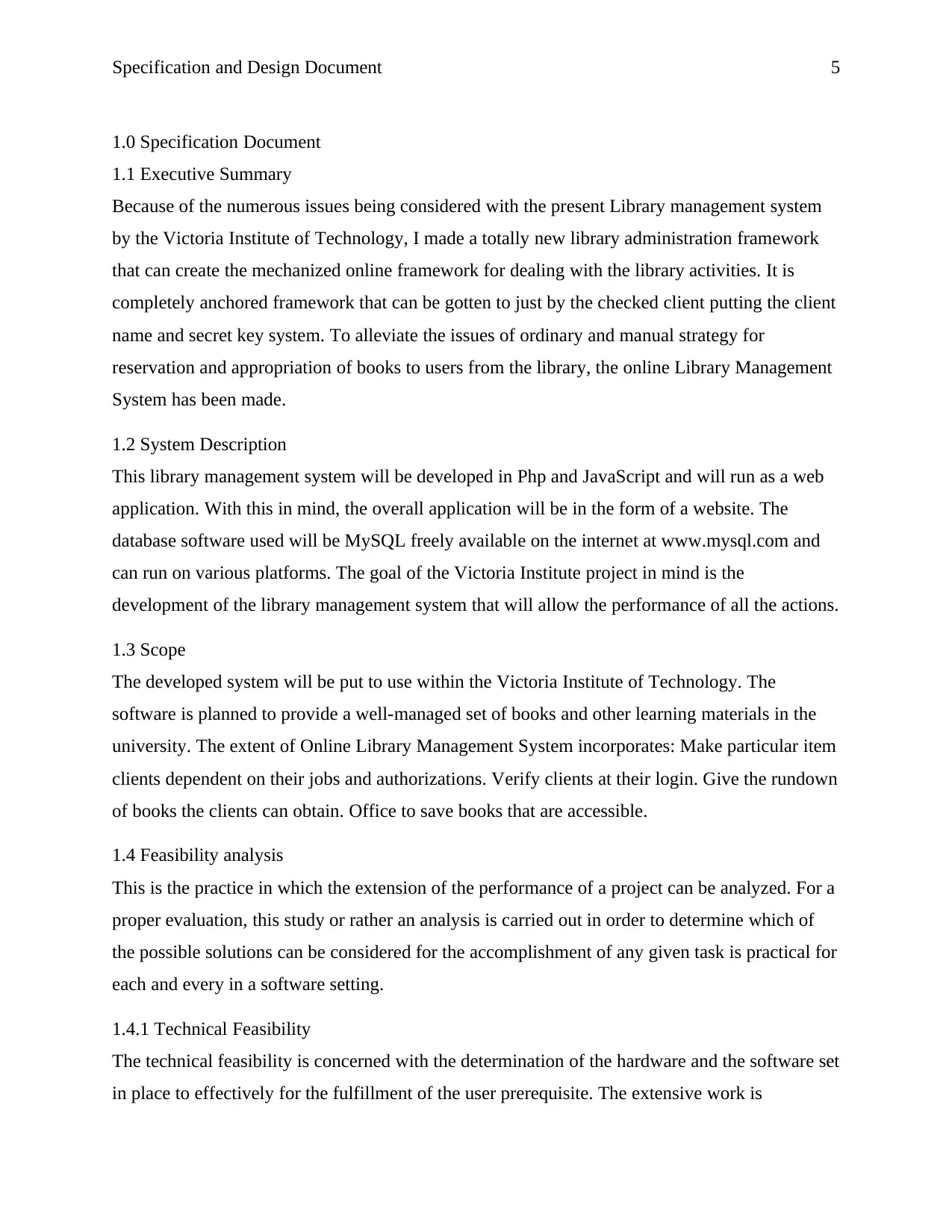
1.0 Specification Document
1.1 Executive Summary
Because of the numerous issues being considered with the present Library management system
by the Victoria Institute of Technology, I made a totally new library administration framework
that can create the mechanized online framework for dealing with the library activities. It is
completely anchored framework that can be gotten to just by the checked client putting the client
name and secret key system. To alleviate the issues of ordinary and manual strategy for
reservation and appropriation of books to users from the library, the online Library Management
System has been made.
1.2 System Description
This library management system will be developed in Php and JavaScript and will run as a web
application. With this in mind, the overall application will be in the form of a website. The
database software used will be MySQL freely available on the internet at www.mysql.com and
can run on various platforms. The goal of the Victoria Institute project in mind is the
development of the library management system that will allow the performance of all the actions.
1.3 Scope
The developed system will be put to use within the Victoria Institute of Technology. The
software is planned to provide a well-managed set of books and other learning materials in the
university. The extent of Online Library Management System incorporates: Make particular item
clients dependent on their jobs and authorizations. Verify clients at their login. Give the rundown
of books the clients can obtain. Office to save books that are accessible.
1.4 Feasibility analysis
This is the practice in which the extension of the performance of a project can be analyzed. For a
proper evaluation, this study or rather an analysis is carried out in order to determine which of
the possible solutions can be considered for the accomplishment of any given task is practical for
each and every in a software setting.
1.4.1 Technical Feasibility
The technical feasibility is concerned with the determination of the hardware and the software set
in place to effectively for the fulfillment of the user prerequisite. The extensive work is
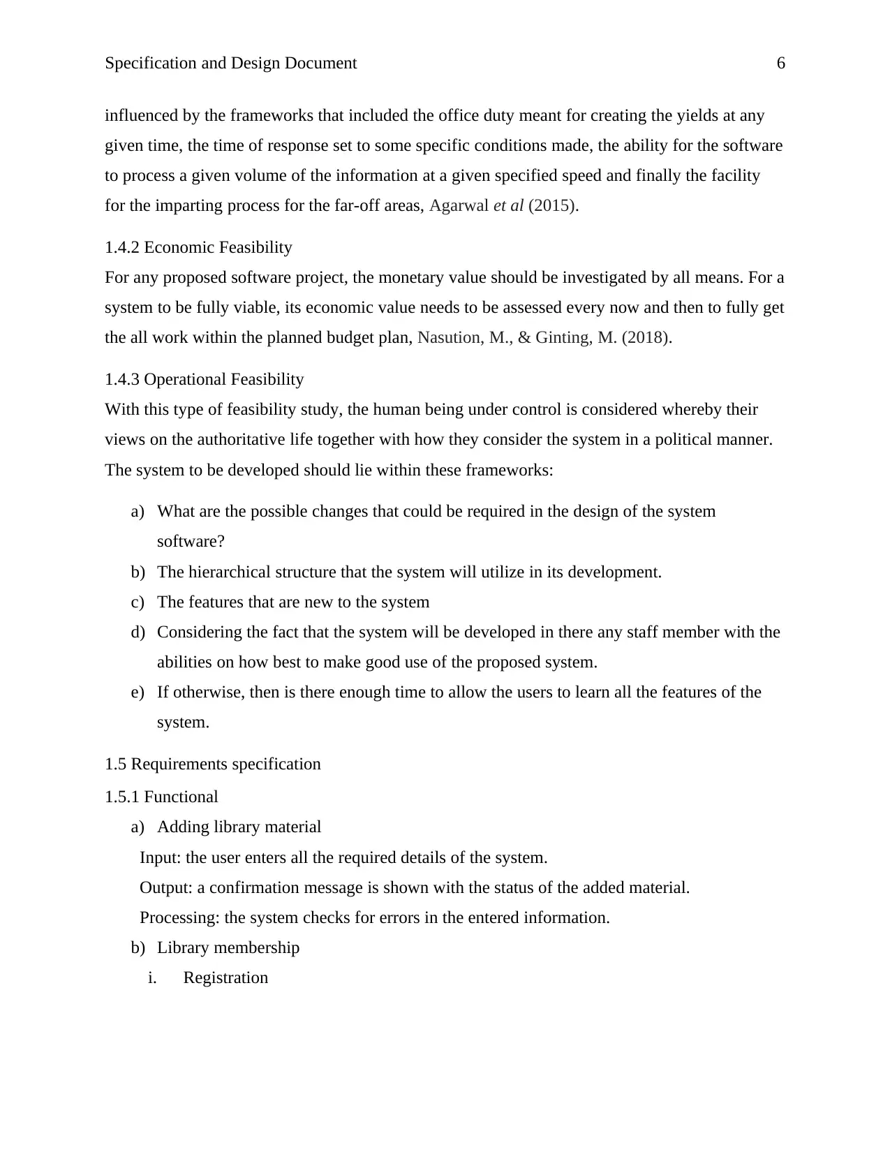
Specification and Design Document 6
influenced by the frameworks that included the office duty meant for creating the yields at any
given time, the time of response set to some specific conditions made, the ability for the software
to process a given volume of the information at a given specified speed and finally the facility
for the imparting process for the far-off areas, Agarwal et al (2015).
1.4.2 Economic Feasibility
For any proposed software project, the monetary value should be investigated by all means. For a
system to be fully viable, its economic value needs to be assessed every now and then to fully get
the all work within the planned budget plan, Nasution, M., & Ginting, M. (2018).
1.4.3 Operational Feasibility
With this type of feasibility study, the human being under control is considered whereby their
views on the authoritative life together with how they consider the system in a political manner.
The system to be developed should lie within these frameworks:
a) What are the possible changes that could be required in the design of the system
software?
b) The hierarchical structure that the system will utilize in its development.
c) The features that are new to the system
d) Considering the fact that the system will be developed in there any staff member with the
abilities on how best to make good use of the proposed system.
e) If otherwise, then is there enough time to allow the users to learn all the features of the
system.
1.5 Requirements specification
1.5.1 Functional
a) Adding library material
Input: the user enters all the required details of the system.
Output: a confirmation message is shown with the status of the added material.
Processing: the system checks for errors in the entered information.
b) Library membership
i. Registration
⊘ This is a preview!⊘
Do you want full access?
Subscribe today to unlock all pages.

Trusted by 1+ million students worldwide
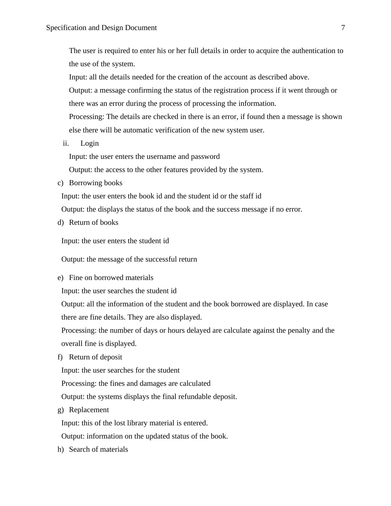
Specification and Design Document 7
The user is required to enter his or her full details in order to acquire the authentication to
the use of the system.
Input: all the details needed for the creation of the account as described above.
Output: a message confirming the status of the registration process if it went through or
there was an error during the process of processing the information.
Processing: The details are checked in there is an error, if found then a message is shown
else there will be automatic verification of the new system user.
ii. Login
Input: the user enters the username and password
Output: the access to the other features provided by the system.
c) Borrowing books
Input: the user enters the book id and the student id or the staff id
Output: the displays the status of the book and the success message if no error.
d) Return of books
Input: the user enters the student id
Output: the message of the successful return
e) Fine on borrowed materials
Input: the user searches the student id
Output: all the information of the student and the book borrowed are displayed. In case
there are fine details. They are also displayed.
Processing: the number of days or hours delayed are calculate against the penalty and the
overall fine is displayed.
f) Return of deposit
Input: the user searches for the student
Processing: the fines and damages are calculated
Output: the systems displays the final refundable deposit.
g) Replacement
Input: this of the lost library material is entered.
Output: information on the updated status of the book.
h) Search of materials
Paraphrase This Document
Need a fresh take? Get an instant paraphrase of this document with our AI Paraphraser
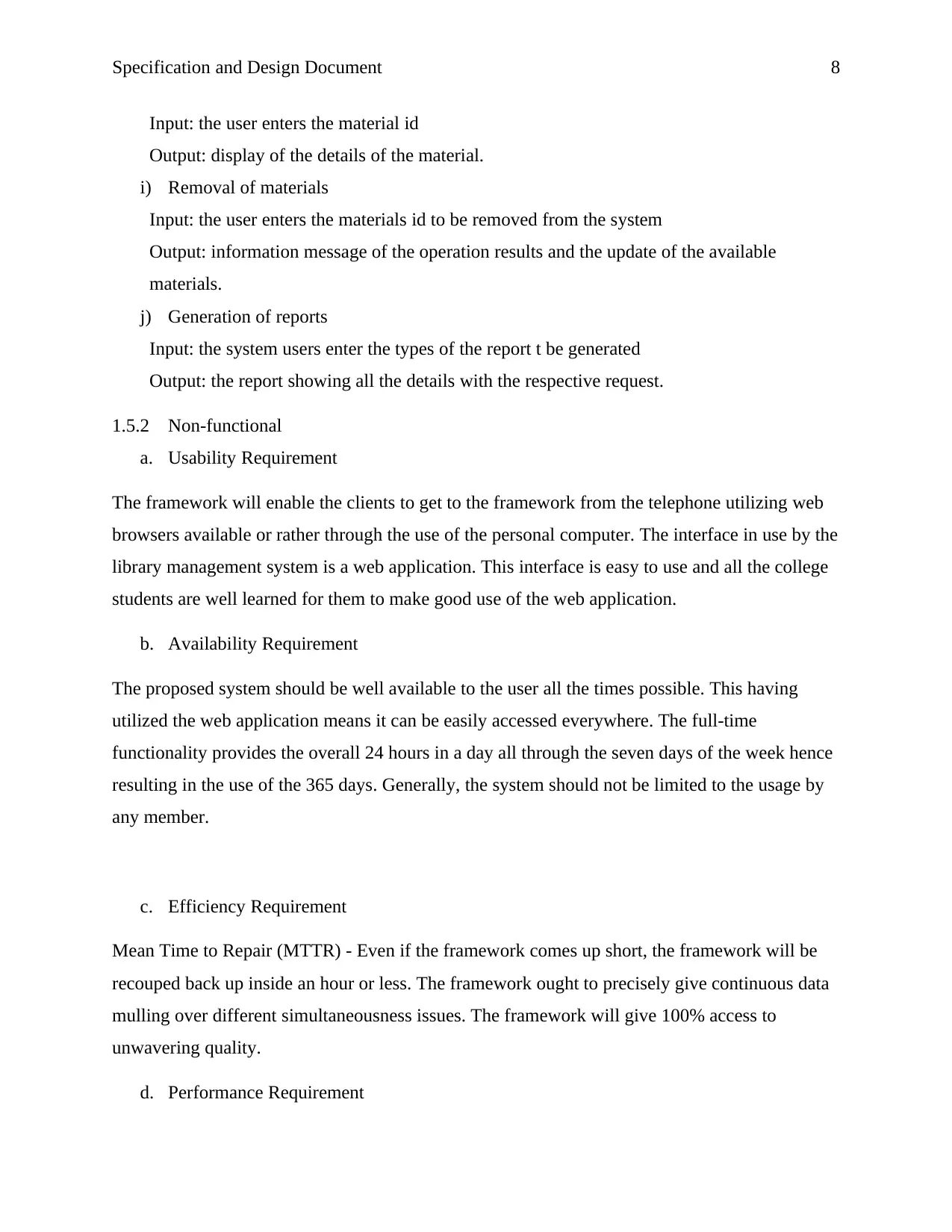
Specification and Design Document 8
Input: the user enters the material id
Output: display of the details of the material.
i) Removal of materials
Input: the user enters the materials id to be removed from the system
Output: information message of the operation results and the update of the available
materials.
j) Generation of reports
Input: the system users enter the types of the report t be generated
Output: the report showing all the details with the respective request.
1.5.2 Non-functional
a. Usability Requirement
The framework will enable the clients to get to the framework from the telephone utilizing web
browsers available or rather through the use of the personal computer. The interface in use by the
library management system is a web application. This interface is easy to use and all the college
students are well learned for them to make good use of the web application.
b. Availability Requirement
The proposed system should be well available to the user all the times possible. This having
utilized the web application means it can be easily accessed everywhere. The full-time
functionality provides the overall 24 hours in a day all through the seven days of the week hence
resulting in the use of the 365 days. Generally, the system should not be limited to the usage by
any member.
c. Efficiency Requirement
Mean Time to Repair (MTTR) - Even if the framework comes up short, the framework will be
recouped back up inside an hour or less. The framework ought to precisely give continuous data
mulling over different simultaneousness issues. The framework will give 100% access to
unwavering quality.
d. Performance Requirement
Specification and Design Document 9
The data is invigorated relying on whether a few updates have happened or not in the
application. The framework will be permitted to take additional time while doing huge handling
employment.
1.6 Constraints
All the operations about the materials in the library are to be well managed. Values should be
correctly entered and updated regularly to ensure that all the information kept in are correct and
all the operation that involve the mathematical calculations should be well processed. The
configuration of any system comes along with its own challenges especially when there is a need
to operative in a given selected language, Fuggetta & Di Nitto (2014).
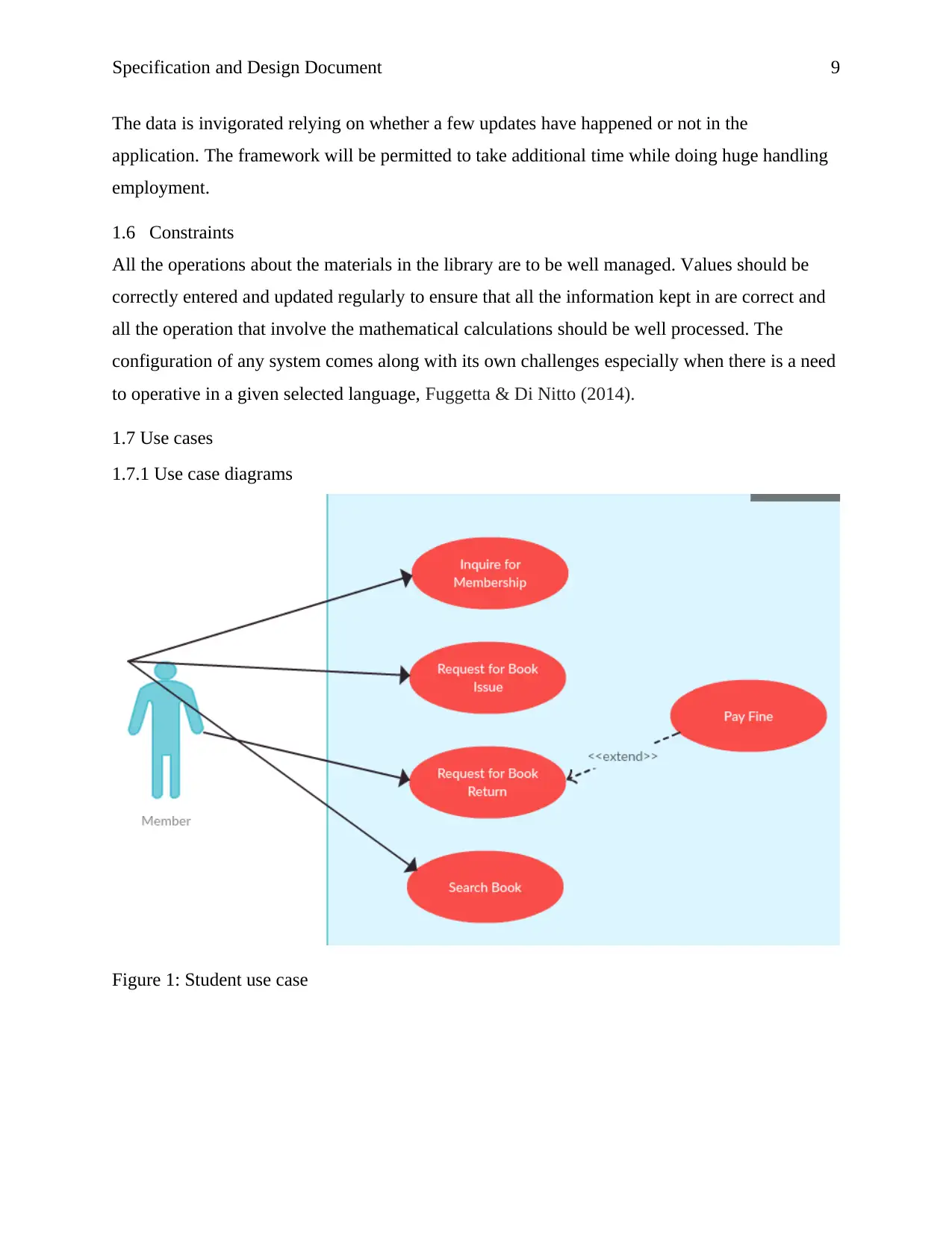
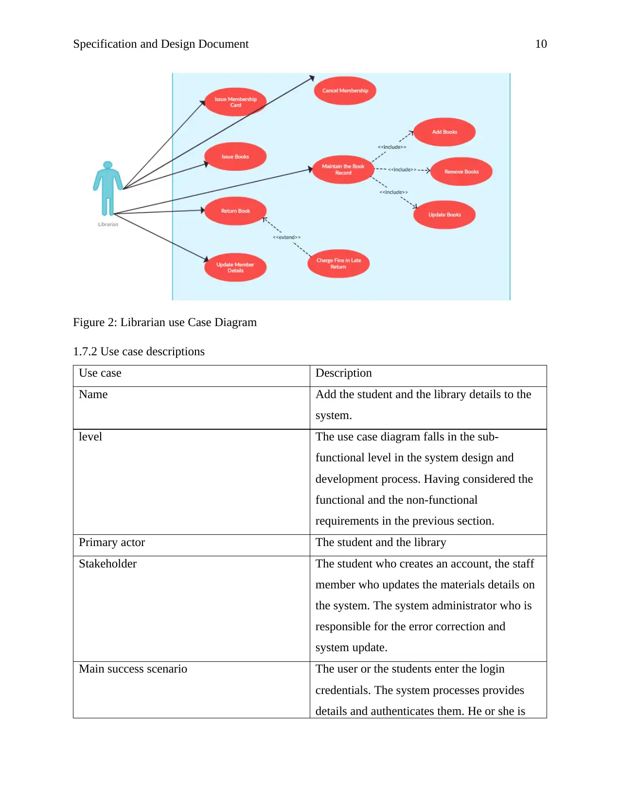
1.7 Use cases
1.7.1 Use case diagrams
Figure 1: Student use case
⊘ This is a preview!⊘
Do you want full access?
Subscribe today to unlock all pages.

Trusted by 1+ million students worldwide
Specification and Design Document 10
Figure 2: Librarian use Case Diagram
1.7.2 Use case descriptions
Use case Description
Name Add the student and the library details to the
system.
level The use case diagram falls in the sub-
functional level in the system design and
development process. Having considered the
functional and the non-functional
requirements in the previous section.
Primary actor The student and the library
Stakeholder The student who creates an account, the staff
member who updates the materials details on
the system. The system administrator who is
responsible for the error correction and
system update.
Main success scenario The user or the students enter the login
credentials. The system processes provides
details and authenticates them. He or she is
Paraphrase This Document
Need a fresh take? Get an instant paraphrase of this document with our AI Paraphraser
Specification and Design Document 11
given the permit to proceed to the other
features of the website.
Alternative flow During the test, the system is undertaking
through a simple registration process where
the user creates an account with incorrect
details apart from the required, probably there
will be an error. This is solved by the expert
instantly.
Specific requirement The time required for the system to process
all the login and registration request should be
less than a minute.
Specification and Design Document 12
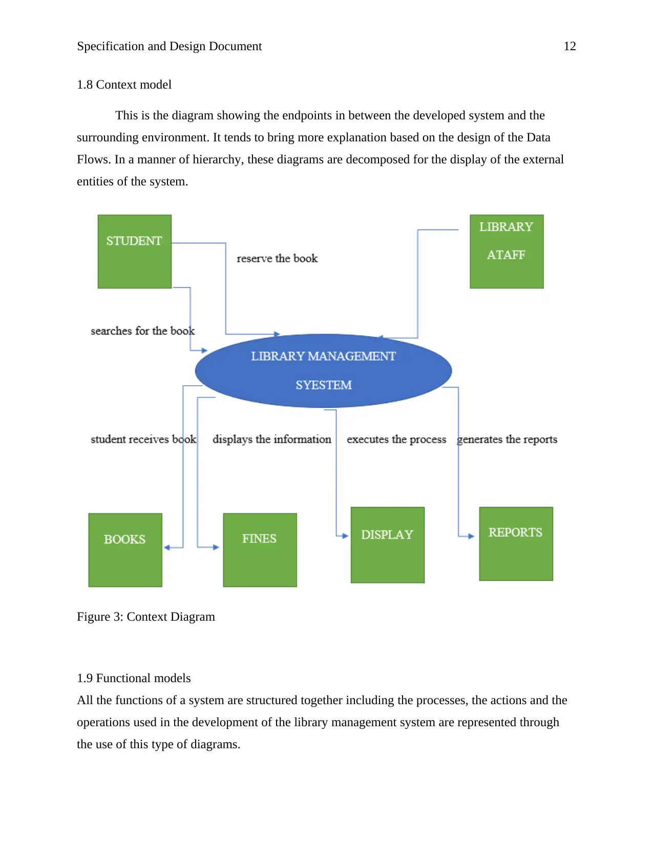
1.8 Context model
This is the diagram showing the endpoints in between the developed system and the
surrounding environment. It tends to bring more explanation based on the design of the Data
Flows. In a manner of hierarchy, these diagrams are decomposed for the display of the external
entities of the system.
Figure 3: Context Diagram
1.9 Functional models
All the functions of a system are structured together including the processes, the actions and the
operations used in the development of the library management system are represented through
the use of this type of diagrams.
⊘ This is a preview!⊘
Do you want full access?
Subscribe today to unlock all pages.

Trusted by 1+ million students worldwide
1 out of 21
Related Documents
Your All-in-One AI-Powered Toolkit for Academic Success.
+13062052269
info@desklib.com
Available 24*7 on WhatsApp / Email
![[object Object]](/_next/static/media/star-bottom.7253800d.svg)
Unlock your academic potential
Copyright © 2020–2026 A2Z Services. All Rights Reserved. Developed and managed by ZUCOL.


![UNI Library System Analysis: Project Report, [University Name]](/_next/image/?url=https%3A%2F%2Fdesklib.com%2Fmedia%2Fimages%2Fmb%2F488dc136f95047de91d331ef0b472565.jpg&w=256&q=75)