OpenHAWK: Object-Oriented Design of a UAV Controller System
VerifiedAdded on 2019/09/16
|6
|2436
|263
Project
AI Summary
This project focuses on the design and analysis of the OpenHAWK, a low-cost multirotor UAV controller, using object-oriented modeling techniques and UML diagrams. The assignment requires students to specify the behavior of the UAV controller, which includes arming and disarming logic, various flight modes (STABILISE, ALTITUDE, HOVER), autonomous flight capabilities with waypoint navigation, and several failsafe features like Return to Launch (RTL), Kill Throttle, and Land programs. Students are tasked with performing requirements analysis, creating use case diagrams, identifying candidate objects and classes, developing object sequence diagrams, constructing class diagrams, and designing state machine diagrams. Furthermore, the project involves system design, including communication diagrams, activity diagrams for arming and failsafe logic, and timing diagrams for performance analysis. The goal is to apply object-oriented modeling to analyze, specify, and design a real-time system, demonstrating the use of software tools to facilitate the modeling methods. The solution includes a detailed report with UML deliverables as per the marking criteria, encompassing various aspects of the UAV controller's functionality and failsafe mechanisms.
OpenHAWK: A low-cost multirotor UAV (unmanned aerial vehicle)
controller
This assessment asks you to apply the object-oriented model to analyse
and design a scenario described below. You are required to document the
processes in accordance with the UML deliverables set out in the Marking
Criteria.
This is an individual coursework, so must be completed individually!
Learning Outcome to be assessed
LO4. Apply Object Oriented modelling methods to the analysis,
specification and design of real-time systems / applications.
LO5. Use software tools to facilitate the application of the modelling
methods.
Detail of the task
A new hardware and software platform, the OpenHAWK, has been
designed, in order to facilitate low-cost Unmanned Aerial Vehicle (i.e.
drone) assembly and operation. It is designed to be fitted to an end user’s
choice of multirotor platform, and provides full authority flight control and
autonomous mission planning and execution. You are required to specify
behaviour for this Unmanned Aerial Vehicle (UAV) controller system.
A full description of a flight controller is beyond the scope of this
assignment; for background research, you may find it helpful to look at
two open-source projects; the PixHawk PX4 platform
(https://goo.gl/dsG9rZ) and the Ardupilot Copter flight controller
software/firmware (http://goo.gl/U73dkh). While you are encouraged to
clarify and augment this specification with any features from your own
research, remember the specification is a simplified description of a UAV
flight controller, appropriate for the assignment weighting (40%) and
duration. Be careful you don’t overcomplicate your problem!
The system will be supervised and operated by a ground pilot, as with any
radio control aircraft; but the system will provide a degree of autonomous
flight (e.g. waypoint flying) and several failsafe features. Typically, a full
system consists of the OpenHAWK, the host multirotor, flight motors and
propellers, an alert siren, a GNSS (Global Navigation Satellite
System) module/antenna, a radio telemetry module (data link), a
Inertial Measurement Unit (IMU – a combined gyroscope,
accelerometer, and magnetometer module), a barometer (pressure
altimeter), and a power supply (typically a LiPo battery) with voltage and
current monitoring. Finally, a dedicated control radio receiver module is
connected to specialised analogue inputs for elevator (pitch), aileron (roll),
rudder (yaw) and throttle (lift/collective equivalent) channels. This allows a
ground “pilot” to instruct the aircraft to fly, in real-time, via its flight
controls.
Paraphrase This Document
Need a fresh take? Get an instant paraphrase of this document with our AI Paraphraser
Outside assignment scope: Initial hardware setup is outside of the
scope of your analysis and design process. You can safely assume the
system and its peripherals are connected correctly and powered.
Additionally, you can assume suitable feedback mechanisms (e.g. PID
controllers) exist to convert desired flight inputs (e.g. pitch, throttle, etc)
alongside attitude data (i.e. IMU) into appropriate control outputs (i.e.
speeds for each propeller/motor), and a function exists to calculate a
heading between a pair of locations.
Arming and Disarming: Many UAVs are “multirotors”, and have a
number of unguarded propellers, each of which can be rotating at >10K
rpm at full throttle. Propeller blades are typically either strong
nylon/plastic or carbon fibre, and there is a significant risk of serious injury
or death if a propeller hits a person – particularly at full throttle. To help
prevent accidental injury when preparing and servicing the UAV, the
system must operate arming logic. This logic operates as follows:
When the system is first powered up, it is “disarmed”. The motors
receive no power when disarmed.
When the user wants the system to permit flight, they must
ensure the throttle is set to idle, and then send an arm command
from their radio transmitter. The UAV performs some failsafe checks
(detailed
later), and if all is well, sounds a high-tone siren for 1s and then
enters “armed” mode.
In armed mode, three significant operations occur:
o it will store the position at which it is armed (its “launch site”), if it has a
good GNSS signal, otherwise it will invalidate any previous launch site.
o the propellers begin to spin slowly, and the UAV is able to respond to
flight control input.
o it should report its attitude (pitch/roll), heading (yaw), and (if available)
latitude and longitude at
2s intervals via its telemetry link.
If the UAV remains at throttle idle for a period of 10s, it sounds a low
siren for 1s, and returns to
“disarmed” status.
Normal and Assisted Flight: The UAV controller will support 3 modes of
pilot-controlled operation – STABILSE, ALTITUDE and HOVER. Flight
dynamics calculations are provided by PID controllers (a
mathematical feedback model) for each flight mode; the controller you are
specifying needs only route the requisite data through the appropriate PID
and adjust each motor speeds accordingly. To operate the UAV reliably,
this sense->PID->actuator feedback loop must occur at a minimum rate of
100Hz.
The STABILISE PID requires the fewest operational sensors; the IMU must
provide accurate gyro and accelerometer readings across 3 axes - pitch,
yaw, and roll. Pilot inputs are translated to thrust levels across the UAV’s
propeller motors. e.g. roll left requires increased right thrust and
decreased left thrust; this would speed up the right-hand propellers, and
slow down the propellers on the left-hand side, thus causing it to roll (i.e.
rotate about its front-to-back axis.). It automatically returns to level
attitude when controls are centred, although it will drift in the wind and
requires the pilot to control throttle manually to maintain altitude.
The ALTITUDE PID builds on STABILSE and requires additionally that the
UAV’s barometer is working correctly; it provides similar flight control to
STABLISE, except that when the throttle control is centred, the UAV will
automatically adjust its throttle in an attempt to maintain a consistent
altitude.
In HOVER Mode, the system takes again greater authority over flight
control. This obeys the rules set out in ALTITUDE, but with additional
stabilisation. From a pilot perspective, when all flight controls are returned
to centre, the UAV will hold its position, automatically altering
pitch/roll/yaw to compensate for wind/drift. This needs all previous sensor
information, along with the GNSS satellite data (for position). Each PID
monitors the inputs for unexpected readings. If more than 5 such readings
occur in a 10s period, a “glitch” fault should be logged against the
offending sensor, and reported via the telemetry link.
Automatic Flight: The UAV can also be programmed for autonomic flight
operation via its telemetry link. This involves sending a list of waypoints -
latitude/longitude co-ordinates, each with an optional altitude. The UAV
can then be set to fly this course automatically, using the following
algorithm:
1. If not armed or no GNSS lock, sound the low siren for 2s, and quit
the flight programme
2. Set HOVER mode, and ascend to 50m altitude above take-off point
and loiter for 5s
3. For each programmed co-ordinate:
1. Sound high-tone siren for 0.5s, and fly towards next co-
ordinate.
2. Once at the specified location, adjust altitude if required.
3. Sound high-tone siren for 1s, and loiter for 5s
4. Once the final co-ordinate is reached, invoke RTL Programme (see
Failsafe below)
Failsafe Features: Owing to the dangers inherent in UAV operation, the
platform should support several “failsafes”. Each of these failsafe criteria
should prevent the craft being armed, if they occur prior to flight, or
activate a specified flight mode if it occurs in flight (indicated below).
Regardless of when the failsafe is triggered, the UAV should sound its low
siren for 2s, and log the failure.
Battery Voltage Low – Activate Return to Launch (RTL)
programme
IMU glitch – Activate Kill Throttle programme
GNSS Signal glitch – Activate Land programme
⊘ This is a preview!⊘
Do you want full access?
Subscribe today to unlock all pages.

Trusted by 1+ million students worldwide
Loss of Radio Control – Activate Return to Launch (RTL)
programme
Failsafe/Autonomous Flight Modes:
Kill Throttle programme: The objective here is simply to ensure the
UAV falls out of the sky while sounding a warning, rather than
drifting about in response to faulty information. It must sound the
high-tone siren at a repetition rate of 3Hz. It should switch to
STABILISE PID flight control & set the throttle control to 0.
RTL programme: This programme requires the UAV’s IMU is
functional and that it has a good GNSS signal, and a valid launch
site stored. Its objective is to fly the UAV, in a controlled manner,
back to the site at which it was launched, and then land it.
1. Switch to HOVER mode if required; ascend/descend to 50m 2.
Sound high-tone siren and loiter here for 5s
3. Fly towards launch site, sounding the low siren at a repetition rate
of 3hz.
4. Once the launch co-ordinates have been reached, switch to the
LAND programme.
Land programme: The objective is, subject to sufficient information, land
the UAV safely. It requires that the barometer is available. Its steps are:
1. Switch to HOVER mode (or ALTITUDE mode if no GNSS signal is
available) and reduce assigned altitude at 5m/sec until 10m is
indicated, then 2m/sec until altitude stops reducing (i.e. UAV
landed).
2. Disarm UAV
What you should hand in
Perform analysis and design of the system using UML, and document all
results obtained from each of the following tasks. You should submit a
written report including results of all the tasks specified, submitted as a
single DOCX or PDF file.
1. Requirements analysis including:
(a) A clear statement of assumptions made, along with justifications. You
should include requirements you’ve omitted because they conflicted or
weren’t consistent. Briefly explain how the system may manage the
feedback loop’s required frequency, and what factors may complicate this.
(b) A full use case diagram, and formal descriptions of all use cases on the
diagram. You may submit separate use case diagrams (e.g. for
subsystems) if desired.
(c) A list of candidate objects, classes and their responsibilities.
(d) An object sequence diagram (OSD) for the normal scenario of each use
case identified in 1(b).
Paraphrase This Document
Need a fresh take? Get an instant paraphrase of this document with our AI Paraphraser
(e) A class diagram, including operations / methods where relevant.
(f) State machine diagrams for all identified classes with operations.
2. System design including:
(a) A CASE-tool-generated system wide communication diagram
(b) Activity diagram(s) for the normal operation of the Arming/Failsafe
logic
(c) Timing Diagram(s) A: for expected performance of the
Arming/Disarming Logic (d) Timing Diagram(s) B: for other time-sensitive
programmes and flight modes
General guidance: This coursework should be started at hand out, not
shortly before hand-in! It is challenging, but achievable; as with the
analysis work in CW1, you need to allow yourself time to read and
interpret the specification, likely several times, allowing it to digest each
time. Applying the OO model is, in parts, an iterative process in order to
get a model which you are satisfied is correct, precise and consistent.
As noted above, you are encouraged to initially carefully study the
specification and make (and document!) assumptions that help to simplify
your model. You will lose marks for removing functionality, but you will not
for interpreting a vague or contradictory specification item in the simplest
possible form. For example, removing failsafe functionality would
constitute removal of a key feature. However, assuming a route algorithm
or a particular Proportional-Integral-Derivative (PID) Controller exists to
simplify automatic flight or basic flight control is acceptable; this is not an
assessment in 3D engine design or aeronautics engineering!
Study the following sections for an overview of the weighting of each
component. Diagrams can be produced using whichever diagramming tool
you prefer, though note the diagrams you submit must at a minimum be
consistent with UML 2.x standards. Visual Paradigm is available in the
labs, via terminalserver, and is also available for download; see the tutor
for further details of the latter.
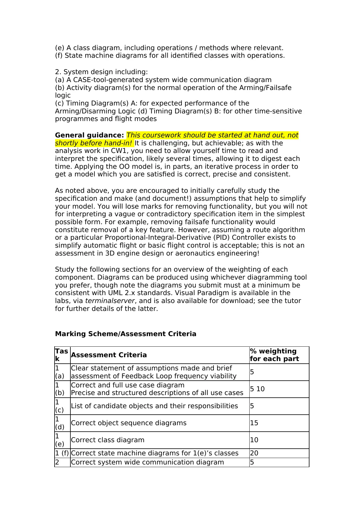
Marking Scheme/Assessment Criteria
Tas
k Assessment Criteria % weighting
for each part
1
(a)
Clear statement of assumptions made and brief
assessment of Feedback Loop frequency viability 5
1
(b)
Correct and full use case diagram
Precise and structured descriptions of all use cases 5 10
1
(c) List of candidate objects and their responsibilities 5
1
(d) Correct object sequence diagrams 15
1
(e) Correct class diagram 10
1 (f) Correct state machine diagrams for 1(e)’s classes 20
2 Correct system wide communication diagram 5
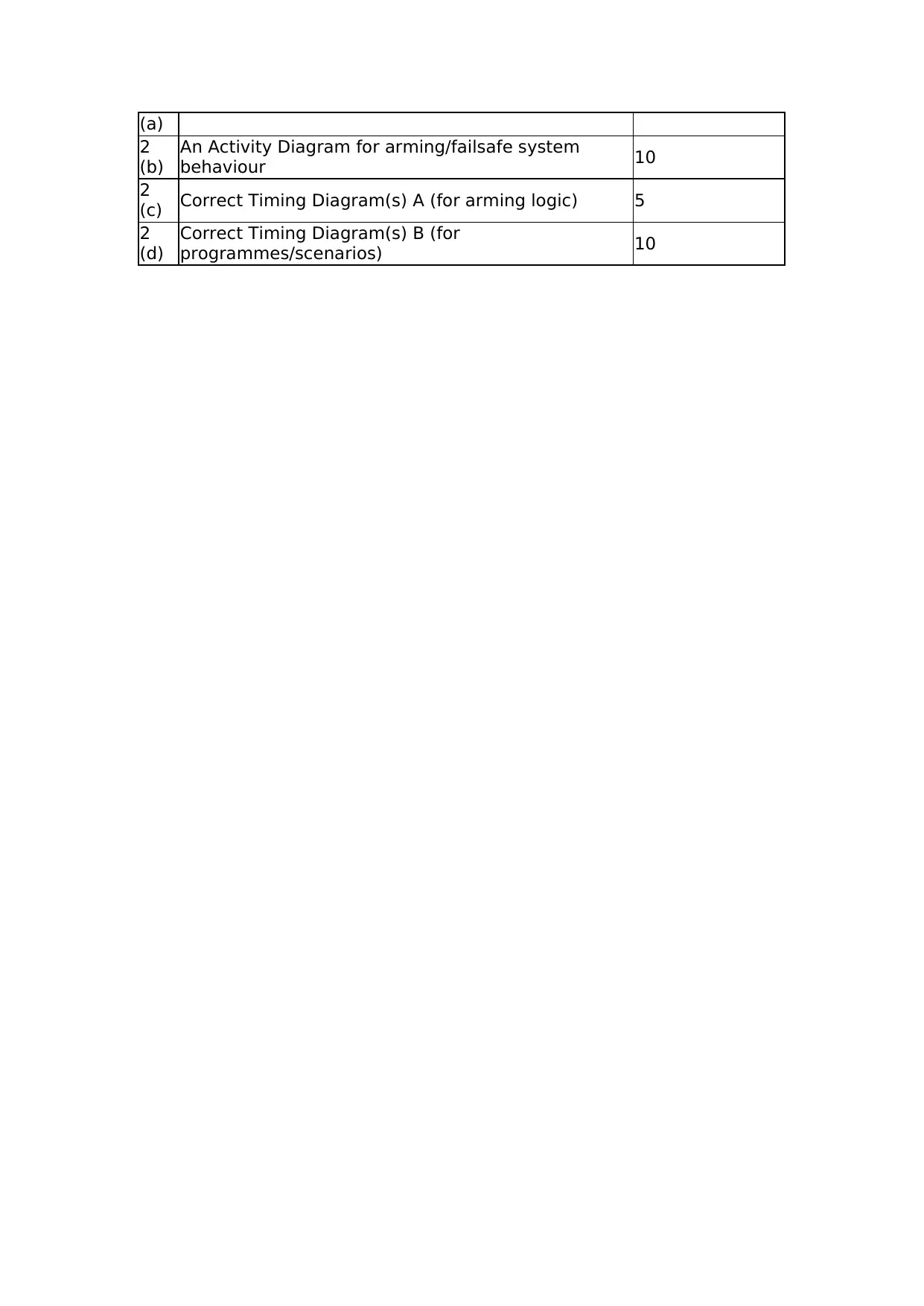
(a)
2
(b)
An Activity Diagram for arming/failsafe system
behaviour 10
2
(c) Correct Timing Diagram(s) A (for arming logic) 5
2
(d)
Correct Timing Diagram(s) B (for
programmes/scenarios) 10
2
(b)
An Activity Diagram for arming/failsafe system
behaviour 10
2
(c) Correct Timing Diagram(s) A (for arming logic) 5
2
(d)
Correct Timing Diagram(s) B (for
programmes/scenarios) 10
⊘ This is a preview!⊘
Do you want full access?
Subscribe today to unlock all pages.

Trusted by 1+ million students worldwide
1 out of 6
Related Documents
Your All-in-One AI-Powered Toolkit for Academic Success.
+13062052269
info@desklib.com
Available 24*7 on WhatsApp / Email
![[object Object]](/_next/static/media/star-bottom.7253800d.svg)
Unlock your academic potential
Copyright © 2020–2025 A2Z Services. All Rights Reserved. Developed and managed by ZUCOL.


