MN503 Internetworking: Network Requirement Analysis and Plan Report
VerifiedAdded on 2023/03/23
|9
|1767
|97
Report
AI Summary
This report provides a detailed analysis of the network requirements for a business operating with five distinct departments, connected via a linear bus topology. It outlines the project scope, network specifications, and a comprehensive network design, including topology and cabling considerations. The report includes IP addressing and subnet calculations, along with a network topology diagram. Furthermore, it details the configuration of switches, routers, access points, and a database server, addressing network security measures. The analysis concludes with key observations and concluding remarks, offering a holistic view of the proposed network solution.

Running head: OVERVIEW ON NETWORKING
Overview on Networking
Name of the Student
Name of the University
Author Note
Overview on Networking
Name of the Student
Name of the University
Author Note
Paraphrase This Document
Need a fresh take? Get an instant paraphrase of this document with our AI Paraphraser
1OVERVIEW ON NETWORKING
Summary
The purpose of this report is to analyse the requirements of the network of a business that operates
with different networks for its five different departments and connects the switches of these
departments in linear bus topology. The report presents a brief scope of the project and summarizes
the network requirements. After that the network design gets discussed in detail where the
topologies and cabling are mentioned. Thereafter, the report presents the IP addressing and subnet
calculation for the different subnetworks and mentions the key findings. After that the network
topology diagram is given and the configuration for switches, routers, access points, database server
as well as the security for the network get talked about. Following this the report ends with
observations in concluding notes.
2OVERVIEW ON NETWORKING
Table of Contents
Introduction...........................................................................................................................................3
Solution.................................................................................................................................................3
Project Scope..........................................................................................................................3
Project Requirements............................................................................................................3
Network Design......................................................................................................................3
IP Addressing..........................................................................................................................3
Network Topology Diagram...................................................................................................3
Switch Configuration..........................................................................................................3
Router Configuration..........................................................................................................3
Access point and server configuration...............................................................................3
Security configuration........................................................................................................3
Conclusion.............................................................................................................................................4
References.............................................................................................................................................5
⊘ This is a preview!⊘
Do you want full access?
Subscribe today to unlock all pages.

Trusted by 1+ million students worldwide
3OVERVIEW ON NETWORKING
Introduction
This report analyses the network requirements of a business which operates with different
networks for the five different departments and has the switches of these departments connected
with the adjacent switch in a linear bus topology. The report begins by presenting the scope of the
project and then goes on to summarize the requirements of the network. After that the network
design gets discussed in detail where the topologies and cabling are mentioned. Thereafter, the
report presents the IP addressing and subnet calculation for the different subnetworks and mentions
the key findings [8]. After that the network topology diagram is given and the configuration for
switches, routers, access points, database server as well as the security for the network get talked
about. Following this the report ends with observations in concluding notes.
Solution
Project Scope
The business whose network design is being proposed comprises of five individual
departments each of which is to have a particular network. All the five different departments are to
access the fourth switch which hosts the Ethernet printer and database server along with the
management and employees. Only the Manager from this department is to have access the finance
which department. Other than that the finance department is not to have direct network
connections.
Project Requirements
There are assumed to be a laptop available for each user. Hence number of laptops per
department is 3. Therefore, total number of laptops for all departments equal 15. These laptops are
to be connected through wireless routers that are connected directly to the main router. The
company looks to be a decent sized firm having five different networks for each of its five respective
departments.
Other than that, each of the department is to provide network to 3 workstations [5]. One of
which hosts the database server and the Ethernet printer that needs to be shared among the devices
of all the departments.
Network Design
The network design is chosen to be quite straight forward. Internet is obtained from the ISPs
or Internet Service Providers through the main router [6]. Part of the connections are provided to all
the 15 laptops through a different network via the wireless router WRT300N [1]. The rest of the
Paraphrase This Document
Need a fresh take? Get an instant paraphrase of this document with our AI Paraphraser
4OVERVIEW ON NETWORKING
connections are passed through a firewall from the main router to the switch that is responsible for
providing access to finance department. From here the network follows a linear bus topology to
connect the other switches of the network. For security reasons, direct connections to the finance
department are blocked by the firewall. Only the manager’s system is allowed to have access over
the devices of finance department through the LAN. The cables to connect the switches and in
between the router and the wireless router are crossover cables while for connecting individual
devices the straight through cables have been used.
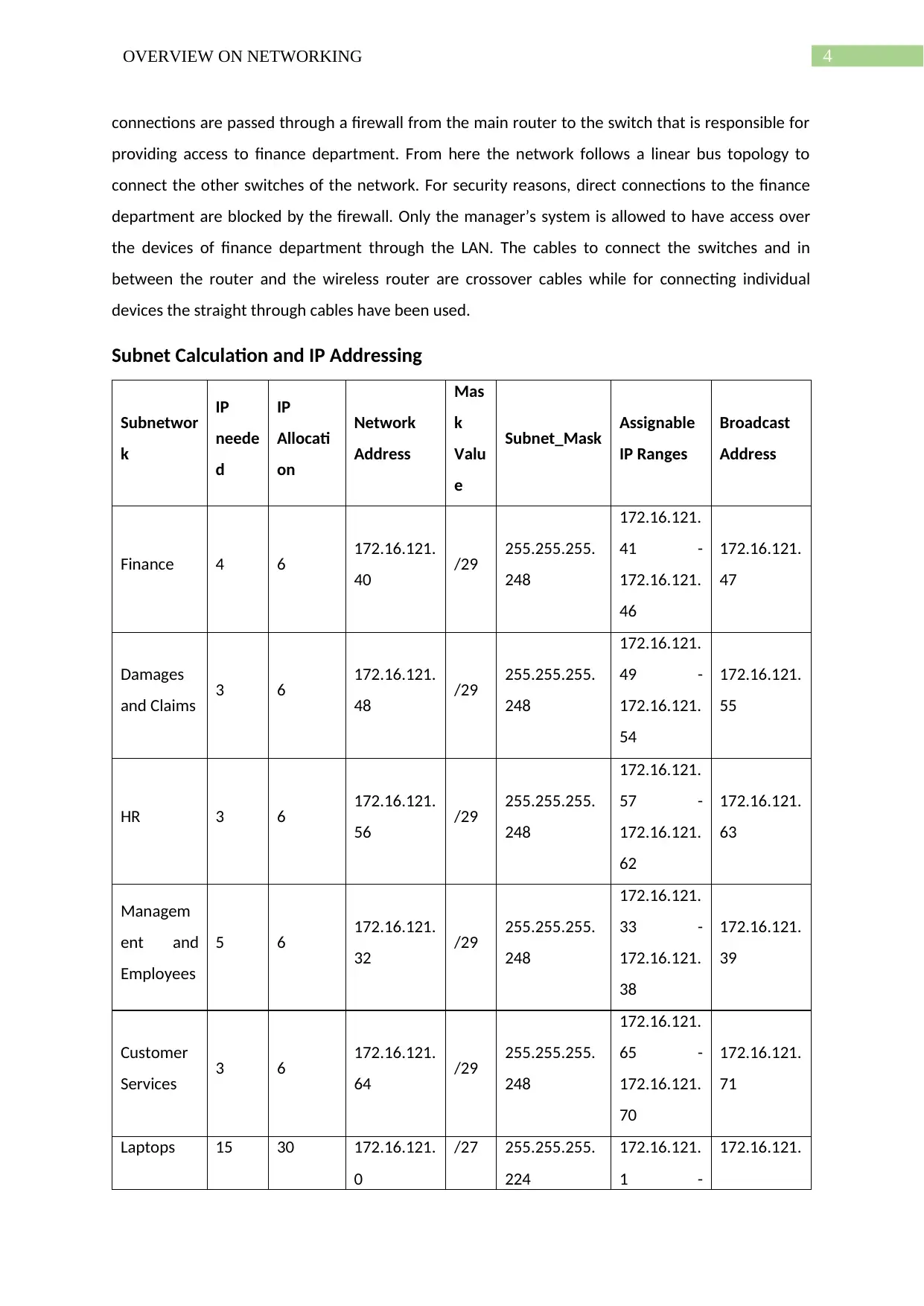
Subnet Calculation and IP Addressing
Subnetwor
k
IP
neede
d
IP
Allocati
on
Network
Address
Mas
k
Valu
e
Subnet_Mask Assignable
IP Ranges
Broadcast
Address
Finance 4 6 172.16.121.
40 /29 255.255.255.
248
172.16.121.
41 -
172.16.121.
46
172.16.121.
47
Damages
and Claims 3 6 172.16.121.
48 /29 255.255.255.
248
172.16.121.
49 -
172.16.121.
54
172.16.121.
55
HR 3 6 172.16.121.
56 /29 255.255.255.
248
172.16.121.
57 -
172.16.121.
62
172.16.121.
63
Managem
ent and
Employees
5 6 172.16.121.
32 /29 255.255.255.
248
172.16.121.
33 -
172.16.121.
38
172.16.121.
39
Customer
Services 3 6 172.16.121.
64 /29 255.255.255.
248
172.16.121.
65 -
172.16.121.
70
172.16.121.
71
Laptops 15 30 172.16.121.
0
/27 255.255.255.
224
172.16.121.
1 -
172.16.121.
5OVERVIEW ON NETWORKING
172.16.121.
30 31
Wireless
Router 2 2 172.16.121.
72 /30 255.255.255.
252
172.16.121.
73 -
172.16.121.
74
172.16.121.
75
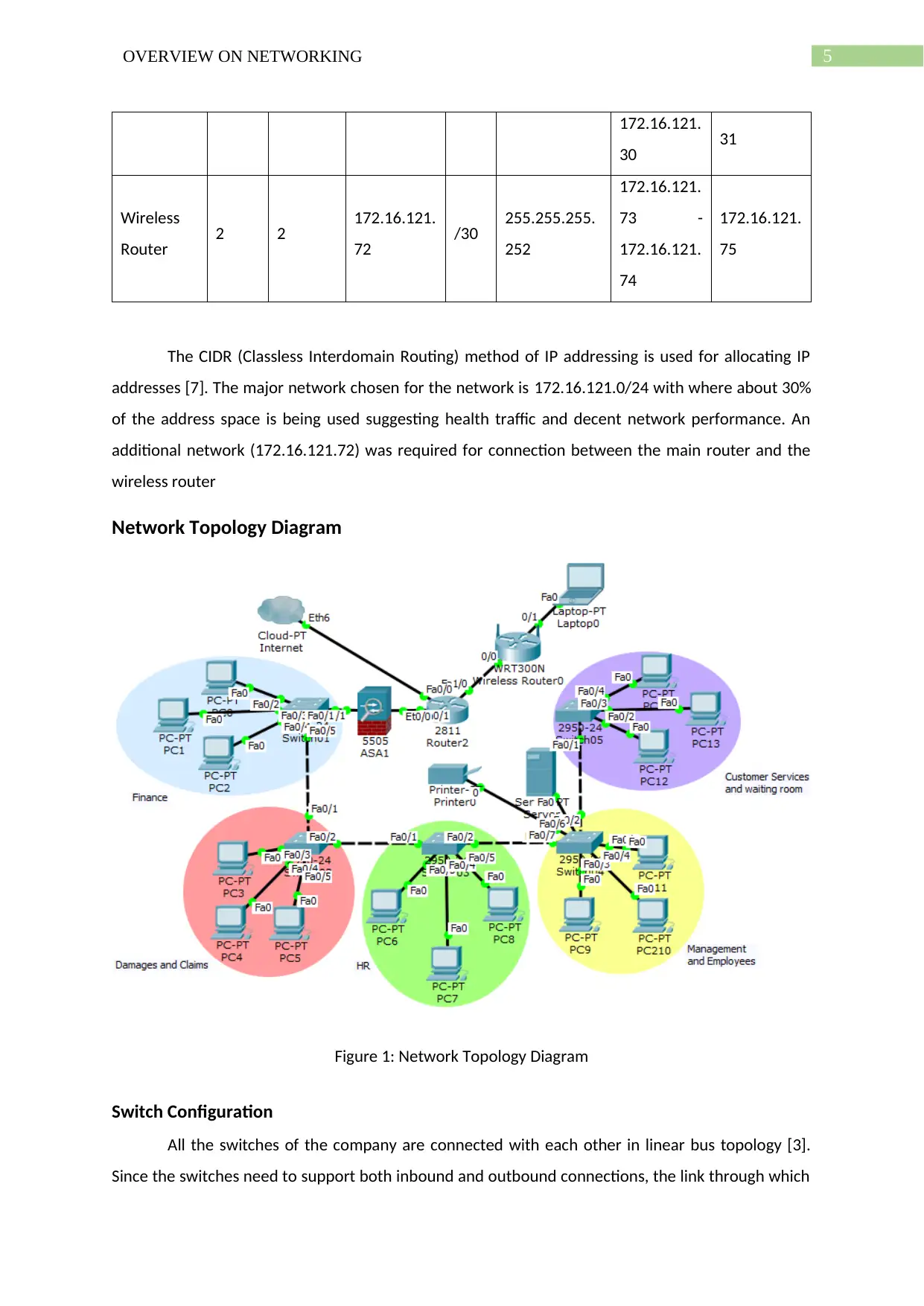
The CIDR (Classless Interdomain Routing) method of IP addressing is used for allocating IP
addresses [7]. The major network chosen for the network is 172.16.121.0/24 with where about 30%
of the address space is being used suggesting health traffic and decent network performance. An
additional network (172.16.121.72) was required for connection between the main router and the
wireless router
Network Topology Diagram
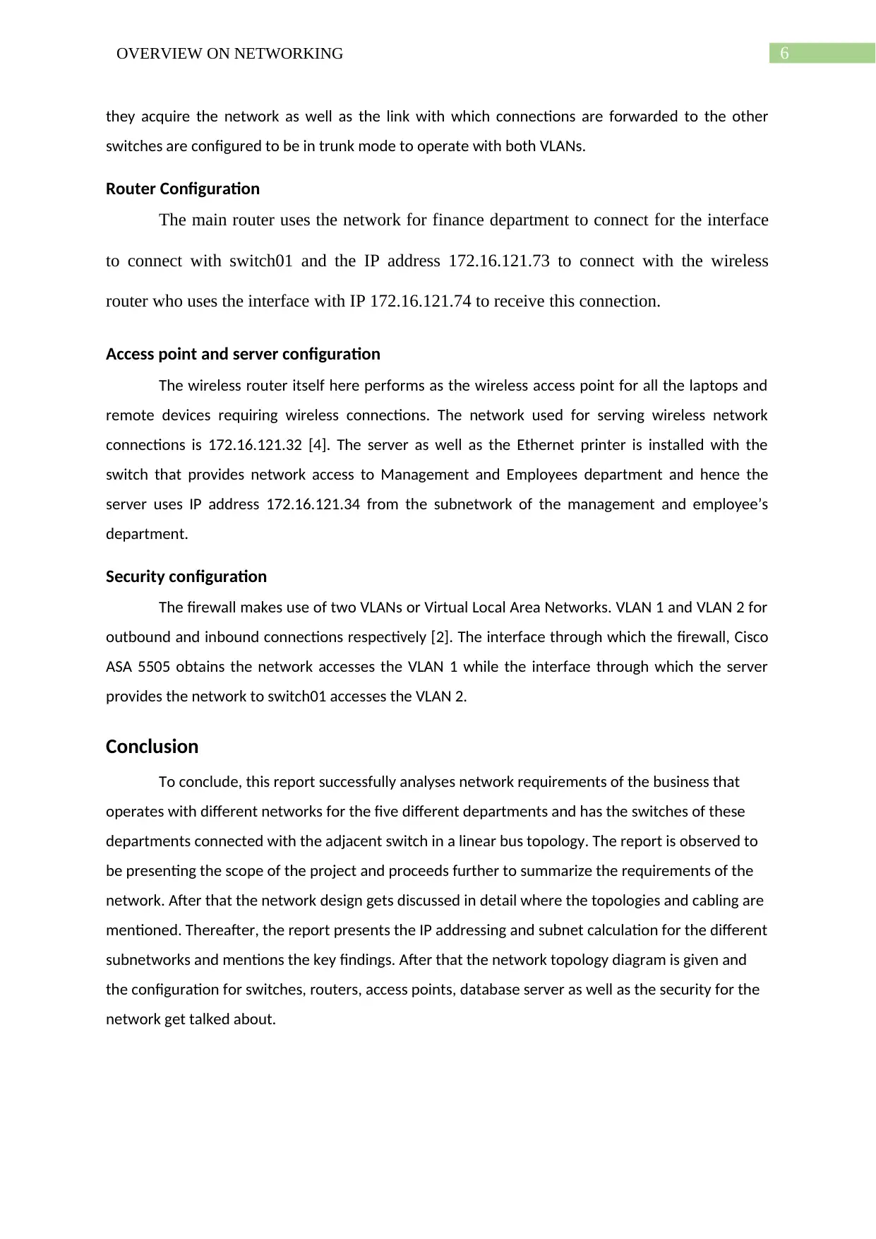
Figure 1: Network Topology Diagram
Switch Configuration
All the switches of the company are connected with each other in linear bus topology [3].
Since the switches need to support both inbound and outbound connections, the link through which
172.16.121.
30 31
Wireless
Router 2 2 172.16.121.
72 /30 255.255.255.
252
172.16.121.
73 -
172.16.121.
74
172.16.121.
75
The CIDR (Classless Interdomain Routing) method of IP addressing is used for allocating IP
addresses [7]. The major network chosen for the network is 172.16.121.0/24 with where about 30%
of the address space is being used suggesting health traffic and decent network performance. An
additional network (172.16.121.72) was required for connection between the main router and the
wireless router
Network Topology Diagram
Figure 1: Network Topology Diagram
Switch Configuration
All the switches of the company are connected with each other in linear bus topology [3].
Since the switches need to support both inbound and outbound connections, the link through which
⊘ This is a preview!⊘
Do you want full access?
Subscribe today to unlock all pages.

Trusted by 1+ million students worldwide
6OVERVIEW ON NETWORKING
they acquire the network as well as the link with which connections are forwarded to the other
switches are configured to be in trunk mode to operate with both VLANs.
Router Configuration
The main router uses the network for finance department to connect for the interface
to connect with switch01 and the IP address 172.16.121.73 to connect with the wireless
router who uses the interface with IP 172.16.121.74 to receive this connection.
Access point and server configuration
The wireless router itself here performs as the wireless access point for all the laptops and
remote devices requiring wireless connections. The network used for serving wireless network
connections is 172.16.121.32 [4]. The server as well as the Ethernet printer is installed with the
switch that provides network access to Management and Employees department and hence the
server uses IP address 172.16.121.34 from the subnetwork of the management and employee’s
department.
Security configuration
The firewall makes use of two VLANs or Virtual Local Area Networks. VLAN 1 and VLAN 2 for
outbound and inbound connections respectively [2]. The interface through which the firewall, Cisco
ASA 5505 obtains the network accesses the VLAN 1 while the interface through which the server
provides the network to switch01 accesses the VLAN 2.
Conclusion
To conclude, this report successfully analyses network requirements of the business that
operates with different networks for the five different departments and has the switches of these
departments connected with the adjacent switch in a linear bus topology. The report is observed to
be presenting the scope of the project and proceeds further to summarize the requirements of the
network. After that the network design gets discussed in detail where the topologies and cabling are
mentioned. Thereafter, the report presents the IP addressing and subnet calculation for the different
subnetworks and mentions the key findings. After that the network topology diagram is given and
the configuration for switches, routers, access points, database server as well as the security for the
network get talked about.
Paraphrase This Document
Need a fresh take? Get an instant paraphrase of this document with our AI Paraphraser
7OVERVIEW ON NETWORKING
References
[1] A. Hakiri, B. Sellami, P. Patil, P. Berthou and A. Gokhale, Managing wireless fog networks using
software-defined networking. In 2017 IEEE/ACS 14th International Conference on Computer Systems
and Applications (AICCSA) (pp. 1149-1156). IEEE., 2017, October.
[2] A. Mehdizadeha, K. Suinggia, M. Mohammadpoorb and H. Haruna, December. Virtual Local Area
Network (VLAN): Segmentation and Security. In The Third International Conference on Computing
Technology and Information Management (ICCTIM2017) (pp. 78-89)., 2017,
[3] D. Agiakatsikas, N.T. Nguyen, Z. Zhao, T. Wu, E. Cetin, O. Diessel and L. Gong, Reconfiguration
control networks for TMR systems with module-based recovery. In 2016 IEEE 24th Annual
International Symposium on Field-Programmable Custom Computing Machines (FCCM) (pp. 88-91).
IEEE. , 2016, May.
[4] D. Jiang, Z. Xu and Z. Lv, A multicast delivery approach with minimum energy consumption for
wireless multi-hop networks. Telecommunication systems, 62(4), pp.771-782., 2016.
[5] M. Dalle Mura, G. Dini and F. Failli, An integrated environment based on augmented reality and
sensing device for manual assembly workstations. Procedia CIRP, 41, pp.340-345., 2016.
[6] T.N. Quach, P. Thaichon, and C. Jebarajakirthy, Internet service providers' service quality and its
effect on customer loyalty of different usage patterns. Journal of Retailing and Consumer Services,
29, pp.104-113., 2016.
[7] W. Huitao, Y. Ruopeng and Z. Xiaofei, April. Research on IP Address Allocation of Tactical
Communication Network. In Journal of Physics: Conference Series (Vol. 1187, No. 4, p. 042105). IOP
Publishing., 2019,
[8] Y. Lee, H. Park, and Y. Lee, Ip geolocation with a crowd-sourcing broadband performance tool.
ACM SIGCOMM Computer Communication Review, 46(1), pp.12-20., 2016.

8OVERVIEW ON NETWORKING
⊘ This is a preview!⊘
Do you want full access?
Subscribe today to unlock all pages.

Trusted by 1+ million students worldwide
1 out of 9
Related Documents
Your All-in-One AI-Powered Toolkit for Academic Success.
+13062052269
info@desklib.com
Available 24*7 on WhatsApp / Email
![[object Object]](/_next/static/media/star-bottom.7253800d.svg)
Unlock your academic potential
Copyright © 2020–2025 A2Z Services. All Rights Reserved. Developed and managed by ZUCOL.


