Analysis and Design of a PID Controller for Brick Cart System
VerifiedAdded on 2023/06/05
|12
|2353
|248
Project
AI Summary
This project details the design and implementation of a PID controller for a brick cart system. The assignment begins with an introduction to control systems and the importance of PID controllers in various engineering applications. The main aim is to control the brick cart's movement from a base point to a destination, considering parameters like velocity, acceleration, and overshoot. The methodology includes an explanation of open and closed-loop control systems, with a focus on the PID controller structure. The Zeigler-Nichols method is employed for tuning the PID parameters. The project includes the derivation of equations for forces, displacement, velocity, and acceleration acting on the brick cart. MATLAB code is provided to simulate the system and analyze the performance of the PID controller with proportional, derivative, and integral terms. The results and discussion section presents the tuning process, including the impact of different PID parameters on the system's response, along with graphical representations of the results. The conclusion summarizes the functionality of each PID parameter, emphasizing the importance of controller tuning and the achieved performance, including overshoot limitations. References to relevant literature are also provided.

Unit name:
Title of experiment:
Date:
Student ID:
Student name:
Title of experiment:
Date:
Student ID:
Student name:
Paraphrase This Document
Need a fresh take? Get an instant paraphrase of this document with our AI Paraphraser
Introduction:
Control system plays important role in the field of engineering covering wide applications
ranging from satellite, missiles, biomedical, electrical, mechanical, and traction. The close
loop control schemes involve, feedback of the system taken from output side and compared
with the desired value of system parameter if any deviation found corrective actions taken
accordingly. Here in this problem brick cart with escalator driven by the engine need to be
controlled with specification of various parameters including velocity, acceleration and the
overshoot. The use of PID controller in close loop environment is suggested to be done.
PID parameter can be set with the use of various conventional and modern techniques.
Here in this particular problem tuning of parameter is done with the use of Zeigler Nichols
method.
Aim:
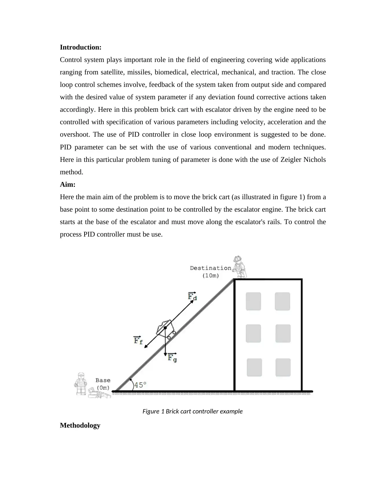
Here the main aim of the problem is to move the brick cart (as illustrated in figure 1) from a
base point to some destination point to be controlled by the escalator engine. The brick cart
starts at the base of the escalator and must move along the escalator's rails. To control the
process PID controller must be use.
Figure 1 Brick cart controller example
Methodology
Two types of control system are generally use in the field of engineering known as open
loop control and closed loop control. Firstly, the system designed under the open loop
environment than if the performance of the system found not satisfactory closed loop
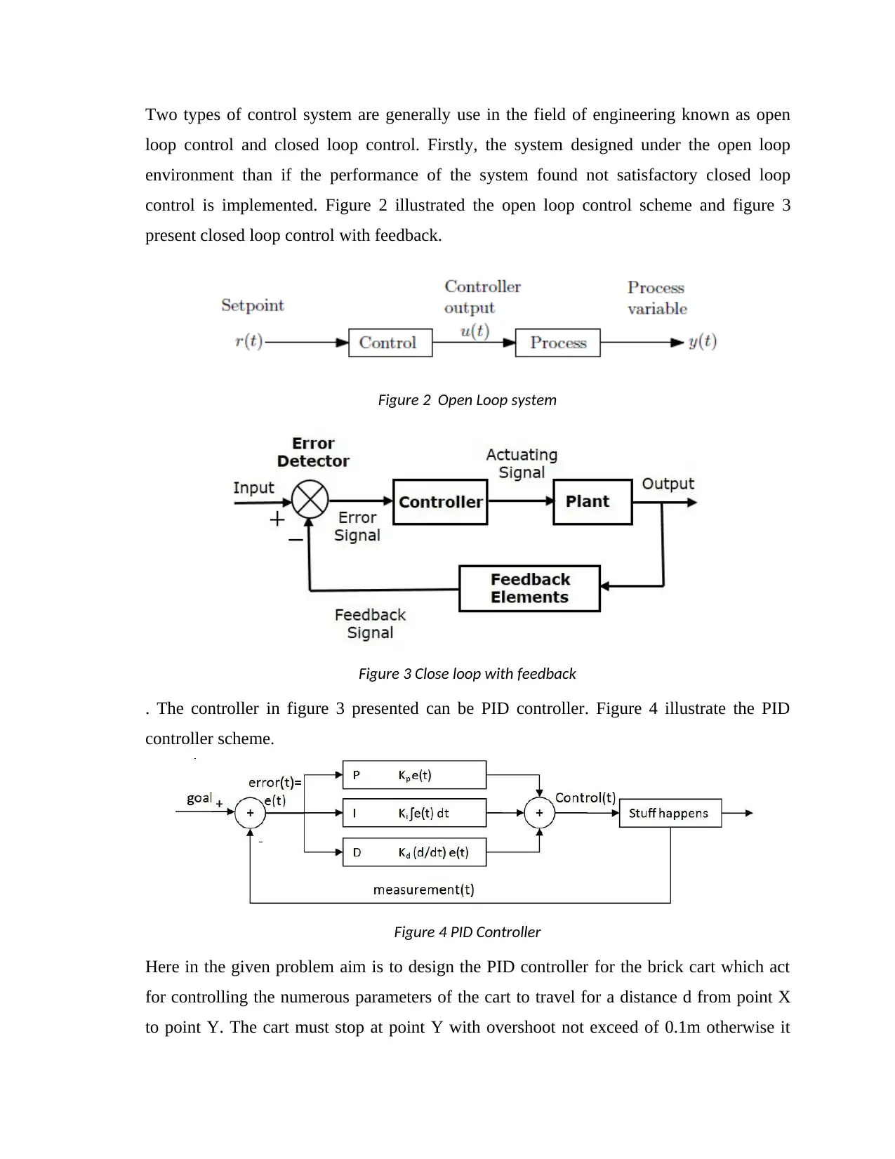
control is implemented. Figure 2 illustrated the open loop control scheme and figure 3
present closed loop control with feedback.
Figure 2 Open Loop system
Figure 3 Close loop with feedback
. The controller in figure 3 presented can be PID controller. Figure 4 illustrate the PID
controller scheme.
Figure 4 PID Controller
Here in the given problem aim is to design the PID controller for the brick cart which act
for controlling the numerous parameters of the cart to travel for a distance d from point X
to point Y. The cart must stop at point Y with overshoot not exceed of 0.1m otherwise it
⊘ This is a preview!⊘
Do you want full access?
Subscribe today to unlock all pages.

Trusted by 1+ million students worldwide
may lead to create catastrophe to the structure.
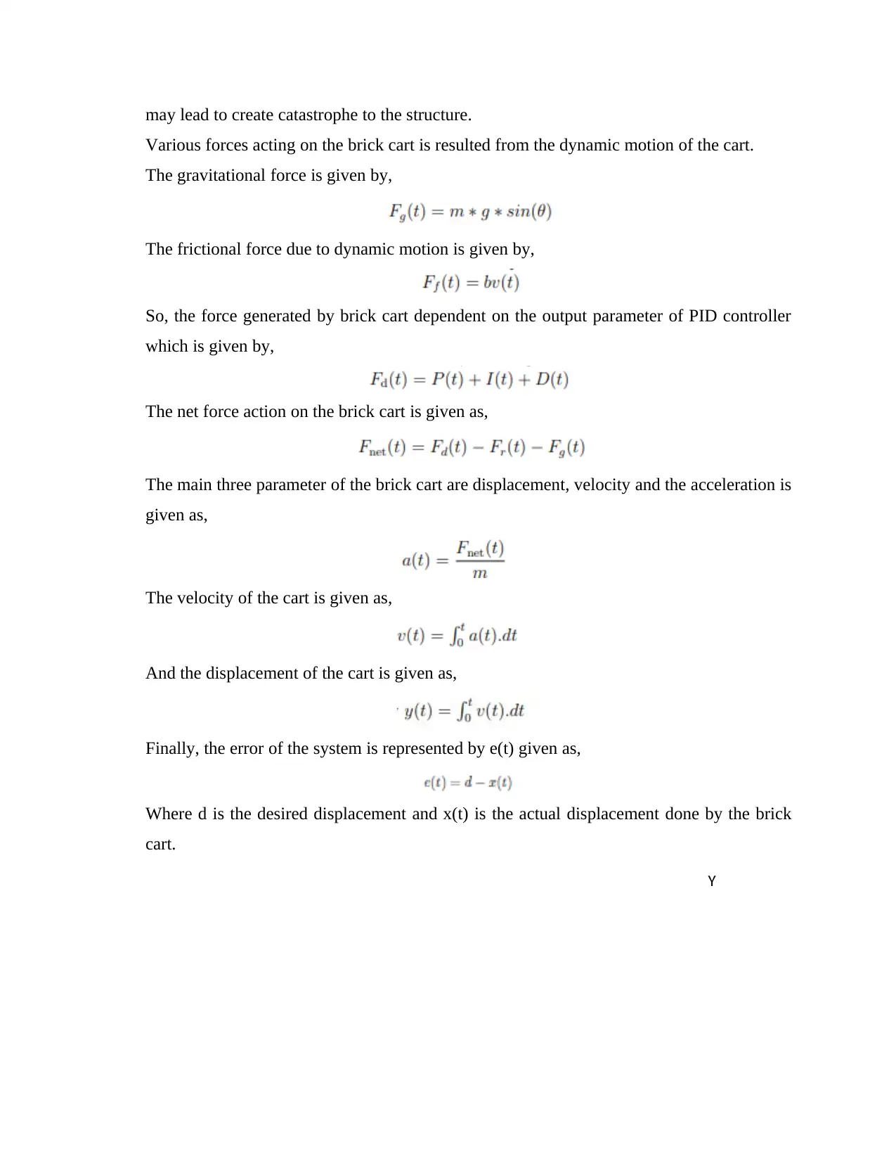
Various forces acting on the brick cart is resulted from the dynamic motion of the cart.
The gravitational force is given by,
The frictional force due to dynamic motion is given by,
So, the force generated by brick cart dependent on the output parameter of PID controller
which is given by,
The net force action on the brick cart is given as,
The main three parameter of the brick cart are displacement, velocity and the acceleration is
given as,
The velocity of the cart is given as,
And the displacement of the cart is given as,
Finally, the error of the system is represented by e(t) given as,
Where d is the desired displacement and x(t) is the actual displacement done by the brick
cart.
Y
Paraphrase This Document
Need a fresh take? Get an instant paraphrase of this document with our AI Paraphraser
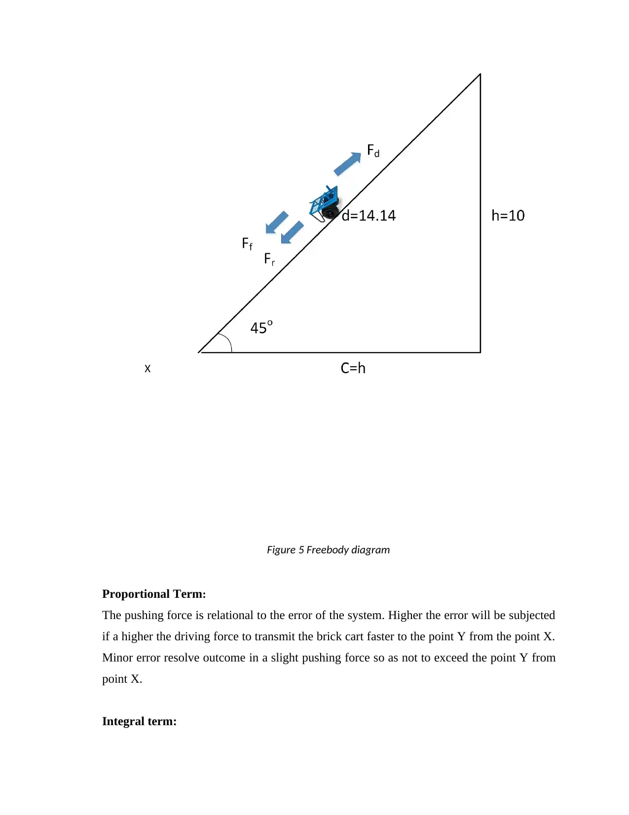
Figure 5 Freebody diagram
Proportional Term:
The pushing force is relational to the error of the system. Higher the error will be subjected
if a higher the driving force to transmit the brick cart faster to the point Y from the point X.
Minor error resolve outcome in a slight pushing force so as not to exceed the point Y from
point X.
Integral term:
X
The importance of the integral term is to overcome the external forces such as frictional and
wind. The term integral is the sum of the error. If the brick cart subjected to error to reach
the destination for a longer period of time the integral term plays important role which
grow and help in to overcome the external forces
Derivative Term:
The importance of the derivative controller is to decreases the oscillations time and the
removes the instability of the system. Derivative term is proportional de/dt of the system.
Here in our case study the derivative parameter is in direct proportion to brick cart velocity.
Zeigler Nichols Method
Above section discussed the role of the PID controller now important task is to set the
value of PID controller. Lots of traditional and modern techniques are exist to set the
controller parameters. Tyreus -Luyben Method[5], Ziegler-Nichols Methods, Modified
Ziegler-Nichols Methods[6, 7], Damped Oscillation Method, C-H-R Method, Cohen-Coon
Method[8], Fertick Method, Ciancone and Marline Method, internal Model Control are the
traditional techniques of PID tuning. Modern methods are one which can be implemented
with the help of PSO[9], GA[10], or with any other meta heuristic methods to tune the PID
controller parameters. From the curve two constants are obtained the delay time L and the
time constant T. It is obtained by drawing a tangent line to the s-curve of the output. To set
the parameter of Kp, Ki, and Kd the table provided below is followed. Ultimately by
increasing the value of proportional parameter which is equated to Kp =Ku is achieved; Ku is
the proportional parameter when the model jumps to oscillate with the period of Tu.
Table 1 Zeigler Nichols Method of PID tuning
Controller Type Kp Ki Kd
P 0.5Ku - -
PI 0.45 Ku 1.2 Kp / Tu -
PID 0.6 Ku 2 Kp / Tu KpTu/8
MATLAB codes
⊘ This is a preview!⊘
Do you want full access?
Subscribe today to unlock all pages.

Trusted by 1+ million students worldwide
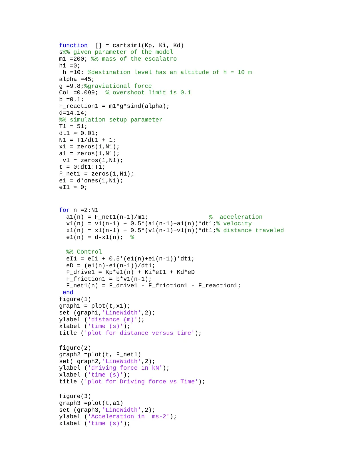
function [] = cartsim1(Kp, Ki, Kd)
s%% given parameter of the model
m1 =200; %% mass of the escalatro
hi =0;
h =10; %destination level has an altitude of h = 10 m
alpha =45;
g =9.8;%graviational force
CoL =0.099; % overshoot limit is 0.1
b =0.1;
F_reaction1 = m1*g*sind(alpha);
d=14.14;
%% simulation setup parameter
T1 = 51;
dt1 = 0.01;
N1 = T1/dt1 + 1;
x1 = zeros(1,N1);
a1 = zeros(1,N1);
v1 = zeros(1,N1);
t = 0:dt1:T1;
F_net1 = zeros(1,N1);
e1 = d*ones(1,N1);
eI1 = 0;
for n =2:N1
a1(n) = F_net1(n-1)/m1; % acceleration
v1(n) = v1(n-1) + 0.5*(a1(n-1)+a1(n))*dt1;% velocity
x1(n) = x1(n-1) + 0.5*(v1(n-1)+v1(n))*dt1;% distance traveled
e1(n) = d-x1(n); %
%% Control
eI1 = eI1 + 0.5*(e1(n)+e1(n-1))*dt1;
eD = (e1(n)-e1(n-1))/dt1;
F_drive1 = Kp*e1(n) + Ki*eI1 + Kd*eD
F_friction1 = b*v1(n-1);
F_net1(n) = F_drive1 - F_friction1 - F_reaction1;
end
figure(1)
graph1 = plot(t,x1);
set (graph1,'LineWidth',2);
ylabel ('distance (m)');
xlabel ('time (s)');
title ('plot for distance versus time');
figure(2)
graph2 =plot(t, F_net1)
set( graph2,'LineWidth',2);
ylabel ('driving force in kN');
xlabel ('time (s)');
title ('plot for Driving force vs Time');
figure(3)
graph3 =plot(t,a1)
set (graph3,'LineWidth',2);
ylabel ('Acceleration in ms-2');
xlabel ('time (s)');
Paraphrase This Document
Need a fresh take? Get an instant paraphrase of this document with our AI Paraphraser
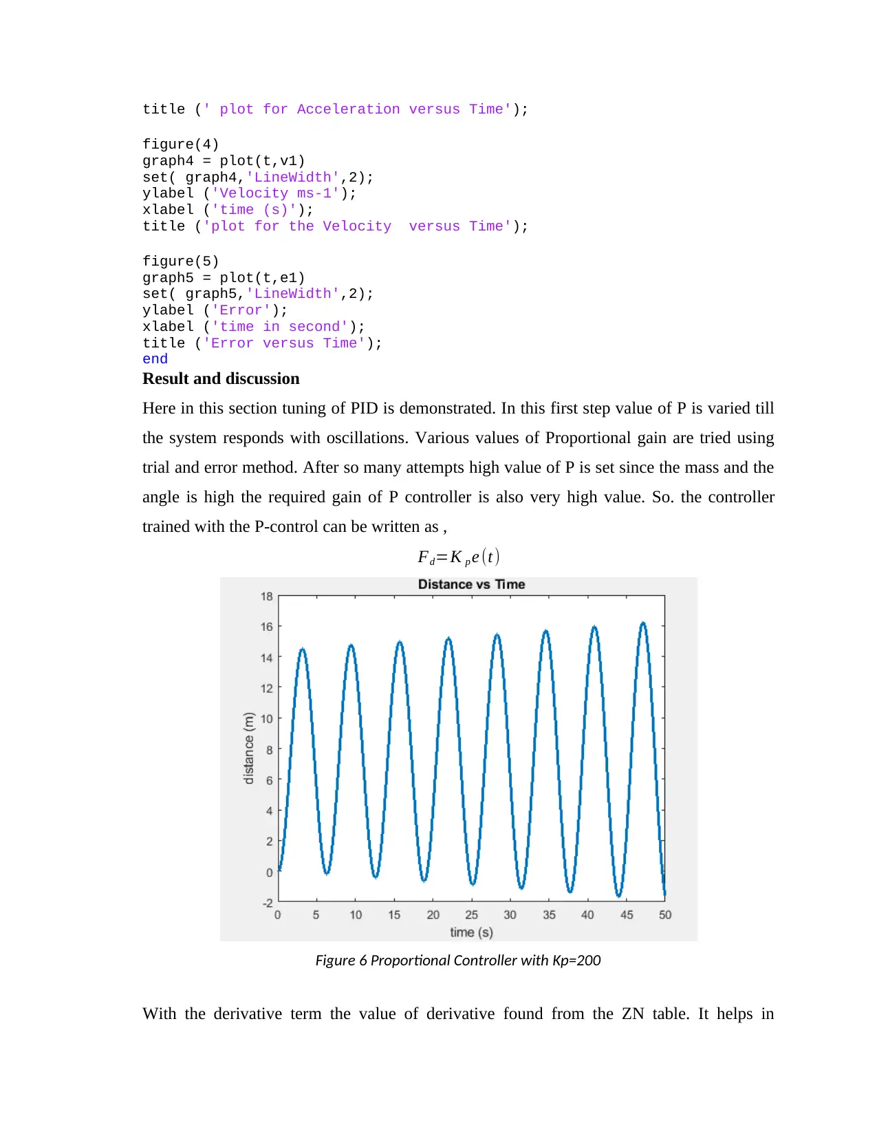
title (' plot for Acceleration versus Time');
figure(4)
graph4 = plot(t,v1)
set( graph4,'LineWidth',2);
ylabel ('Velocity ms-1');
xlabel ('time (s)');
title ('plot for the Velocity versus Time');
figure(5)
graph5 = plot(t,e1)
set( graph5,'LineWidth',2);
ylabel ('Error');
xlabel ('time in second');
title ('Error versus Time');
end
Result and discussion
Here in this section tuning of PID is demonstrated. In this first step value of P is varied till
the system responds with oscillations. Various values of Proportional gain are tried using
trial and error method. After so many attempts high value of P is set since the mass and the
angle is high the required gain of P controller is also very high value. So. the controller
trained with the P-control can be written as ,
Fd=K p e (t)
Figure 6 Proportional Controller with Kp=200
With the derivative term the value of derivative found from the ZN table. It helps in
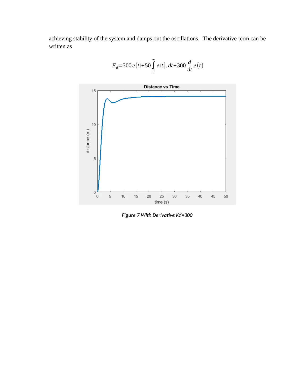
achieving stability of the system and damps out the oscillations. The derivative term can be
written as
Fd=300 e ( t ) +50∫
0
∞
e (t ) . dt+300 d
dt e (t)
Figure 7 With Derivative Kd=300
written as
Fd=300 e ( t ) +50∫
0
∞
e (t ) . dt+300 d
dt e (t)
Figure 7 With Derivative Kd=300
⊘ This is a preview!⊘
Do you want full access?
Subscribe today to unlock all pages.

Trusted by 1+ million students worldwide
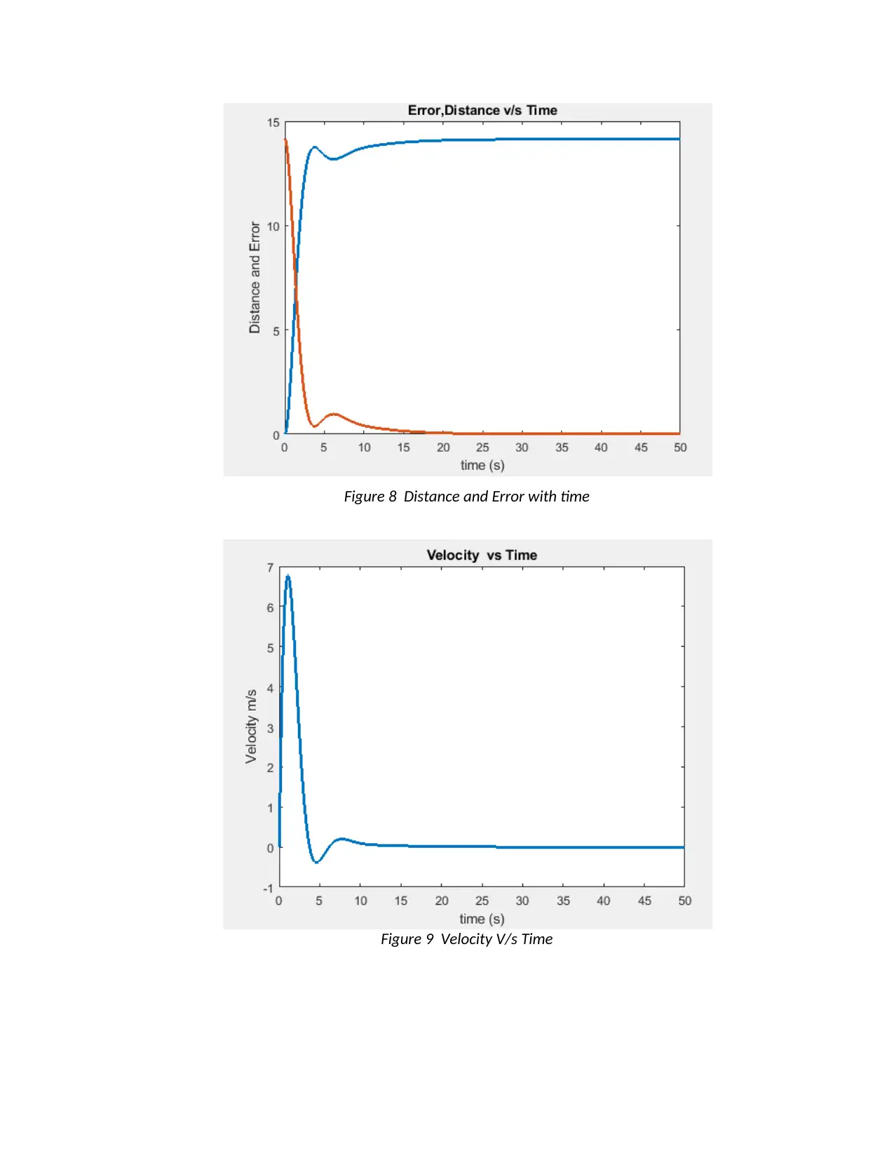
Figure 8 Distance and Error with time
Figure 9 Velocity V/s Time
Figure 9 Velocity V/s Time
Paraphrase This Document
Need a fresh take? Get an instant paraphrase of this document with our AI Paraphraser
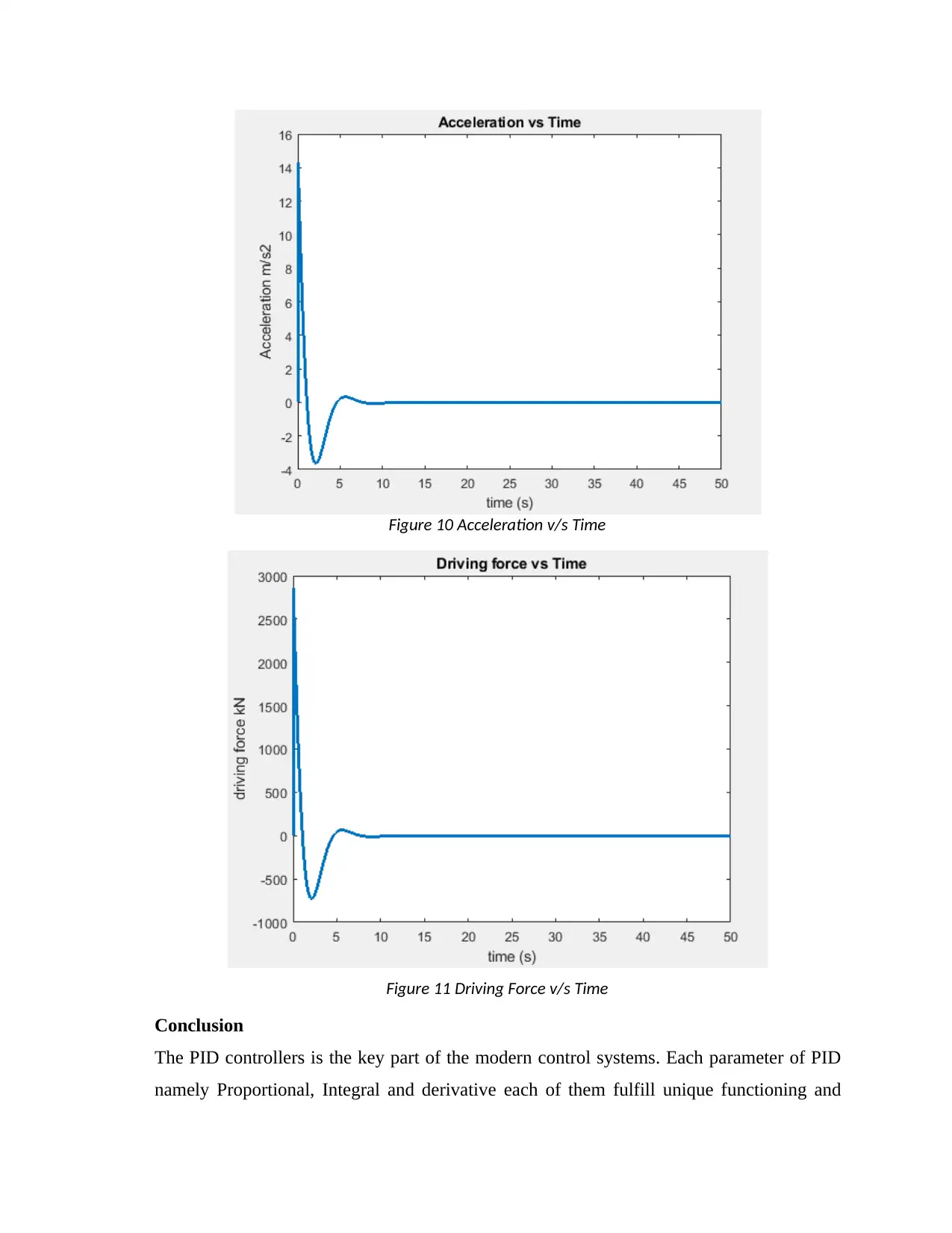
Figure 10 Acceleration v/s Time
Figure 11 Driving Force v/s Time
Conclusion
The PID controllers is the key part of the modern control systems. Each parameter of PID
namely Proportional, Integral and derivative each of them fulfill unique functioning and
Figure 11 Driving Force v/s Time
Conclusion
The PID controllers is the key part of the modern control systems. Each parameter of PID
namely Proportional, Integral and derivative each of them fulfill unique functioning and
helps in controlling the system process. In the case where if the value of gain parameter Kp
is not much large, the brick cart may accelerate rapidly, which can achieve very high
momentum and the overshoot till the point Y. It can again reverse back suddenly and may
oscillate for few moments around the destination point Y. In the case if the value of Kp is
very small, time to reach the destination may be higher the cart still cause oscillation
around the point Y with the higher time of oscillations. So, in the feedback system the
comparator continuously compares the output of the controller with desired system
response based on the deviations the corrective actions are taken. Since the mass and the
angle is high value the gain required for the PID controller is also high in range of
hundreds. The system response shows that it doesn’t overshoot more than 0.1 m with
desired destination travel of 14.14m at the point Y on the slope of the given infrastructure.
References
[1] T.Wiegand, G.J.Sullivan, G.Bjøntegaard and A.Luthra, Overview of the H.264/AVC video
coding standard,IEEE Trans. Circuits System. Video Technology, vol.13, pp. 560-576, July
2003.
[2] T. Sato, "Design of a OPC-based PID controller for controlling a weigh feeder[J]", Control
engineering practice, vol. 18, no. 2, 2010..
[3] D. Misir, H. A. Malki, and G. Chen, "Design and analysis of a fuzzy proportional-integral-
derivative controller," Fuzzy sets and systems, vol. 79, no. 3, pp. 297-314, 1996.
[4] T.-L. Chern and Y.-C. Wu, "Design of integral variable structure controller and application
to electrohydraulic velocity servosystems," in IEE Proceedings D (Control Theory and
Applications), 1991, vol. 138, no. 5, pp. 439-444: IET.
[5] B. D. Tyreus and W. L. Luyben, "Tuning PI controllers for integrator/dead time processes,"
Industrial & Engineering Chemistry Research, vol. 31s, no. 11, pp. 2625-2628, 1992.
[6] P. Meshram and R. G. Kanojiya, "Tuning of PID controller using Ziegler-Nichols method
for speed control of DC motor," in Advances in Engineering, Science and Management
(ICAESM), 2012 International Conference on, 2012, pp. 117-122: IEEE.
[7] S. Singh and R. Mitra, "Comparative analysis of robustness of optimally offline tuned PID
controller and Fuzzy supervised PID controller," 2014 Recent Advances in Engineering and
Computational Sciences (RAECS), Chandigarh, 2014, pp. 1-
[8] S. Tavakoli and M. Tavakoli, "Optimal tuning of PID controllers for first order plus time
delay models using dimensional analysis," in Control and Automation, 2003. ICCA'03.
Proceedings. 4th International Conference on, 2003, pp. 942-946: IEEE.
[9] Z.-L. Gaing, "A particle swarm optimization approach for optimum design of PID
controller in AVR system," IEEE transactions on energy conversion, vol. 19, no. 2, pp.
384-391, 2004.
[10] N. Thomas and D. P. Poongodi, "Position control of DC motor using genetic algorithm
based PID controller," in Proceedings of the World Congress on Engineering, 2009, vol. 2,
pp. 1-3: London, UK.
⊘ This is a preview!⊘
Do you want full access?
Subscribe today to unlock all pages.

Trusted by 1+ million students worldwide
1 out of 12
Related Documents
Your All-in-One AI-Powered Toolkit for Academic Success.
+13062052269
info@desklib.com
Available 24*7 on WhatsApp / Email
![[object Object]](/_next/static/media/star-bottom.7253800d.svg)
Unlock your academic potential
Copyright © 2020–2026 A2Z Services. All Rights Reserved. Developed and managed by ZUCOL.


