Higher Colleges of Technology: Process Control Project Report
VerifiedAdded on 2023/01/19
|13
|2549
|23
Project
AI Summary
This project report provides an in-depth analysis of process control strategies, focusing on feedback, feedforward, and split-range control systems. It begins with an introduction to feedback control, explaining its advantages and disadvantages, and then delves into the application of split-range control in a hydrocarbon liquid-vapor separator. The report details the control mechanism, including the roles of pressure indicating controllers and control valves, and presents a block diagram and valve response graph. Furthermore, it explores the industrial application of feedback-feedforward control in selective slurry flotation, illustrating the control loops and block diagrams involved. The discussion section addresses the benefits of dead bands in split-range control and highlights the advantages and disadvantages of feedforward control, concluding with the advantages of combining feedback and feedforward mechanisms to optimize process control. The project incorporates diagrams and figures to clarify complex concepts, offering a comprehensive understanding of process control principles and their practical applications.
Process Control Project
Process Control Project
Student Name
Higher Colleges of Technology Abu Dhabi Men’s College
ECH 3043: Process Control
Lecturer’s Name
16th April, 2019
1
Process Control Project
Student Name
Higher Colleges of Technology Abu Dhabi Men’s College
ECH 3043: Process Control
Lecturer’s Name
16th April, 2019
1
Paraphrase This Document
Need a fresh take? Get an instant paraphrase of this document with our AI Paraphraser
Process Control Project
Introduction
Feedback is a control strategy that uses data from measured parameters to manipulate other
system variables so as to get an anticipated outcome. In this meachanism, the measured
variable is the controlled variable. This variable is measured and compared to a targeted value
or set-point. The disparity between the actual measured value and the target value is known as
the error. The feedback system works to reduce the error.
There are two types of feedback control which are the negative and the positive feedback.
The negative feedback tends to cause increase/decrease when the change in the measured
variable has decreased/increased respectively. This results in the convergence towards an
equilibrium. In contrast, the positive feedback causes divergence of the system from the
equilibrium.
The feedback control boast of several advantages due to the acquisition of the controller input
from the process output. First and foremost, modelling the controller system is a very simple
technique as no mathematical modelling of the whole system is needed be. Likewise, the
control can be copied from one system to another. Furthermore, unexpected disturbances that
had been unaccounted for during the design phase can also be accounted for (University of
Michigan Chemical Engineering , 2006).
The fact that the feedback control uses the process output its controller input also adds
various disadvantages to the control mechanism which include:
• Control action is taken only when the process output has digressed from set point.
This also includes the digressions that occur at the very beginning of the process.
Furthermore, the output sensor may fail to note the error and the deviation may persist
leading in controller inefficiency.
• Causes system instability in the closed-loop system as response may be oscillatory.
2
Process Control Project
• The feedback controllers do not resolve predictive loads that may cause system
disturbances (University of Michigan Chemical Engineering , 2006).
Finally, the feedback control is a single input single output (SISO) system that can only
obtain signal from a single sensor which is a limiting factor for a system which has multiple
sensors or requires multiple control from a single output. For this reason, more complex
multiple input and multiple output control systems have been developed. Examples are the
split range control and the feedfoward-feedback controls as discussed below.
Split Range Control
The split range control loop is used in situations where there are more than one manipulated
variables (process input) and only one control input.
Industrial Application of Split Range Control
This mechanism is employed in a liquid-vapour hydrocarbon separator. Typical of the split
range controller, the splitter specifies the order in which the valve operate as the output of the
control process (controlled variable) varies.
The figure 1 below is a schematic representation of a hydrocarbon liquid-vapour separator.
The objective of the control mechanism is to maintain the pressure within the vessel within a
specified acceptable range that will allow for the flashing of the hydrocarbon vapours from
the liquid-vapour mixture. The splitter is the pressure indicating controller (PIC) in the
diagram. The controller, PIC, measures and controls the pressure within the separating vessel.
In this case, the controlled variable is the pressure, a primary measurement, within the
separator. The manipulated variables are the flows of the vapour to the flaring section and the
flow of fuel gases into the separator depending on the prevailing state of the controlled
variable. The disturbance in the system is caused by the flow of new feed into the separator
3
⊘ This is a preview!⊘
Do you want full access?
Subscribe today to unlock all pages.
Trusted by 1+ million students worldwide
Process Control Project
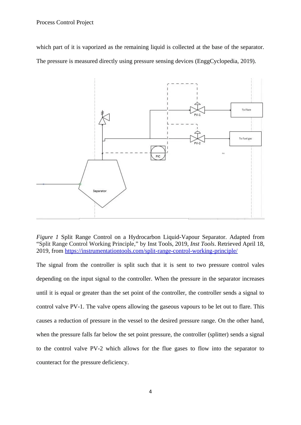
which part of it is vaporized as the remaining liquid is collected at the base of the separator.
The pressure is measured directly using pressure sensing devices (EnggCyclopedia, 2019).
Figure 1 Split Range Control on a Hydrocarbon Liquid-Vapour Separator. Adapted from
“Split Range Control Working Principle,” by Inst Tools, 2019, Inst Tools. Retrieved April 18,
2019, from https://instrumentationtools.com/split-range-control-working-principle/
The signal from the controller is split such that it is sent to two pressure control vales
depending on the input signal to the controller. When the pressure in the separator increases
until it is equal or greater than the set point of the controller, the controller sends a signal to
control valve PV-1. The valve opens allowing the gaseous vapours to be let out to flare. This
causes a reduction of pressure in the vessel to the desired pressure range. On the other hand,
when the pressure falls far below the set point pressure, the controller (splitter) sends a signal
to the control valve PV-2 which allows for the flue gases to flow into the separator to
counteract for the pressure deficiency.
4
Paraphrase This Document
Need a fresh take? Get an instant paraphrase of this document with our AI Paraphraser
Process Control Project
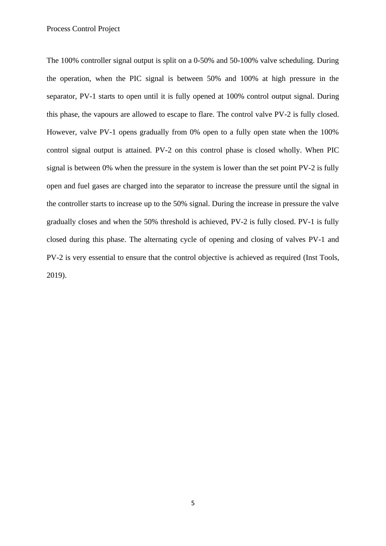
The 100% controller signal output is split on a 0-50% and 50-100% valve scheduling. During
the operation, when the PIC signal is between 50% and 100% at high pressure in the
separator, PV-1 starts to open until it is fully opened at 100% control output signal. During
this phase, the vapours are allowed to escape to flare. The control valve PV-2 is fully closed.
However, valve PV-1 opens gradually from 0% open to a fully open state when the 100%
control signal output is attained. PV-2 on this control phase is closed wholly. When PIC
signal is between 0% when the pressure in the system is lower than the set point PV-2 is fully
open and fuel gases are charged into the separator to increase the pressure until the signal in
the controller starts to increase up to the 50% signal. During the increase in pressure the valve
gradually closes and when the 50% threshold is achieved, PV-2 is fully closed. PV-1 is fully
closed during this phase. The alternating cycle of opening and closing of valves PV-1 and
PV-2 is very essential to ensure that the control objective is achieved as required (Inst Tools,
2019).
5
Process Control Project
0 10 20 30 40 50 60 70 80 90 100
0
10
20
30
40
50
60
70
80
90
100
Split range block
Signal Output
% Valve Opening
PV-2 PV-1
Figure 2 Valve Opening and Closing in Response to Controller Signal Output. Adapted from
“Split Range Control Working Principle,” by Inst Tools, 2019,Inst Tools.. Retrieved April
18,2019, from https://instrumentationtools.com/split-range-control-working-principle/
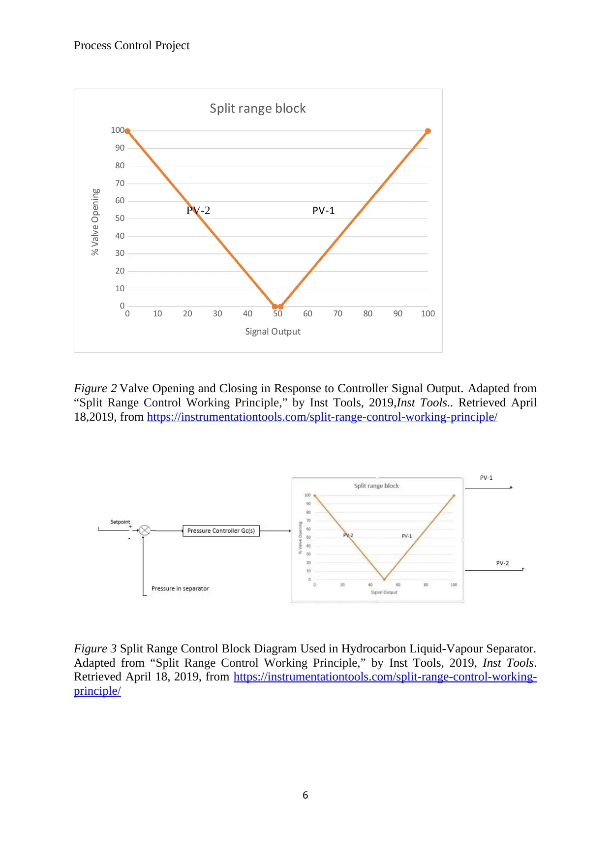
Figure 3 Split Range Control Block Diagram Used in Hydrocarbon Liquid-Vapour Separator.
Adapted from “Split Range Control Working Principle,” by Inst Tools, 2019, Inst Tools.
Retrieved April 18, 2019, from https://instrumentationtools.com/split-range-control-working-
principle/
6
0 10 20 30 40 50 60 70 80 90 100
0
10
20
30
40
50
60
70
80
90
100
Split range block
Signal Output
% Valve Opening
PV-2 PV-1
Figure 2 Valve Opening and Closing in Response to Controller Signal Output. Adapted from
“Split Range Control Working Principle,” by Inst Tools, 2019,Inst Tools.. Retrieved April
18,2019, from https://instrumentationtools.com/split-range-control-working-principle/
Figure 3 Split Range Control Block Diagram Used in Hydrocarbon Liquid-Vapour Separator.
Adapted from “Split Range Control Working Principle,” by Inst Tools, 2019, Inst Tools.
Retrieved April 18, 2019, from https://instrumentationtools.com/split-range-control-working-
principle/
6
⊘ This is a preview!⊘
Do you want full access?
Subscribe today to unlock all pages.
Trusted by 1+ million students worldwide
Process Control Project
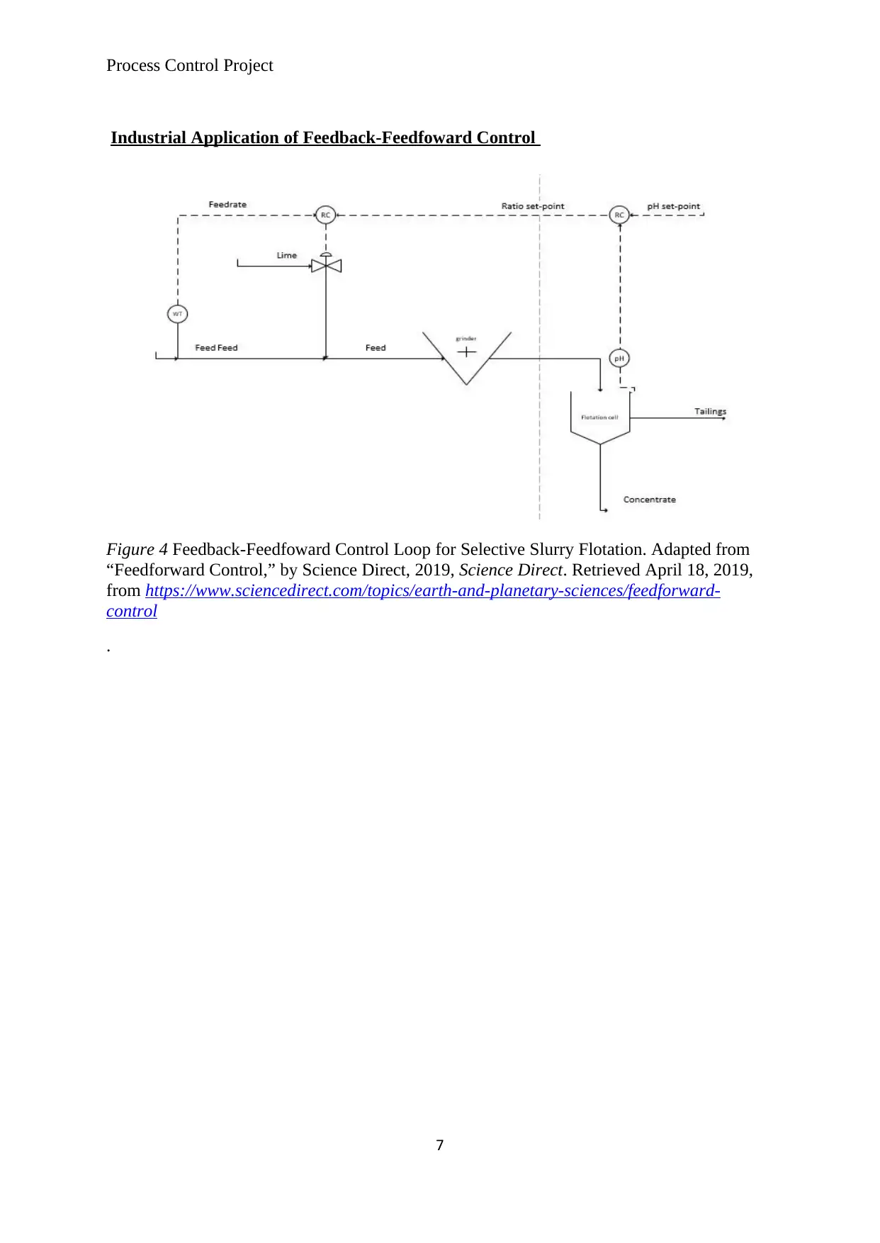
Industrial Application of Feedback-Feedfoward Control
Figure 4 Feedback-Feedfoward Control Loop for Selective Slurry Flotation. Adapted from
“Feedforward Control,” by Science Direct, 2019, Science Direct. Retrieved April 18, 2019,
from https://www.sciencedirect.com/topics/earth-and-planetary-sciences/feedforward-
control
.
7
Paraphrase This Document
Need a fresh take? Get an instant paraphrase of this document with our AI Paraphraser
Process Control Project
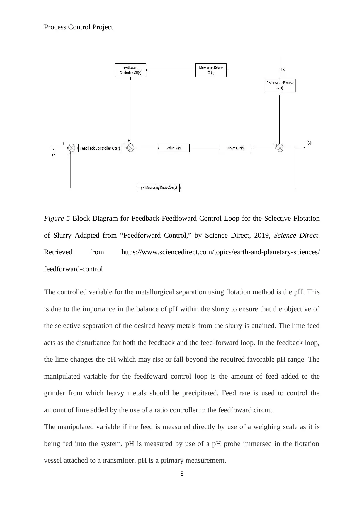
Figure 5 Block Diagram for Feedback-Feedfoward Control Loop for the Selective Flotation
of Slurry Adapted from “Feedforward Control,” by Science Direct, 2019, Science Direct.
Retrieved from https://www.sciencedirect.com/topics/earth-and-planetary-sciences/
feedforward-control
The controlled variable for the metallurgical separation using flotation method is the pH. This
is due to the importance in the balance of pH within the slurry to ensure that the objective of
the selective separation of the desired heavy metals from the slurry is attained. The lime feed
acts as the disturbance for both the feedback and the feed-forward loop. In the feedback loop,
the lime changes the pH which may rise or fall beyond the required favorable pH range. The
manipulated variable for the feedfoward control loop is the amount of feed added to the
grinder from which heavy metals should be precipitated. Feed rate is used to control the
amount of lime added by the use of a ratio controller in the feedfoward circuit.
The manipulated variable if the feed is measured directly by use of a weighing scale as it is
being fed into the system. pH is measured by use of a pH probe immersed in the flotation
vessel attached to a transmitter. pH is a primary measurement.
8
Process Control Project
The pH controller gets a signal from the pH transmitter and changes the flow rate of lime
from the error between the pH measured and the established set-point. This process
constitutes the feedback control loop. In this case, the feedback is a negative feedback as the
action taken is to minimize the error caused by the disturbance or load added to the system,
which is lime for this example.
Discussion
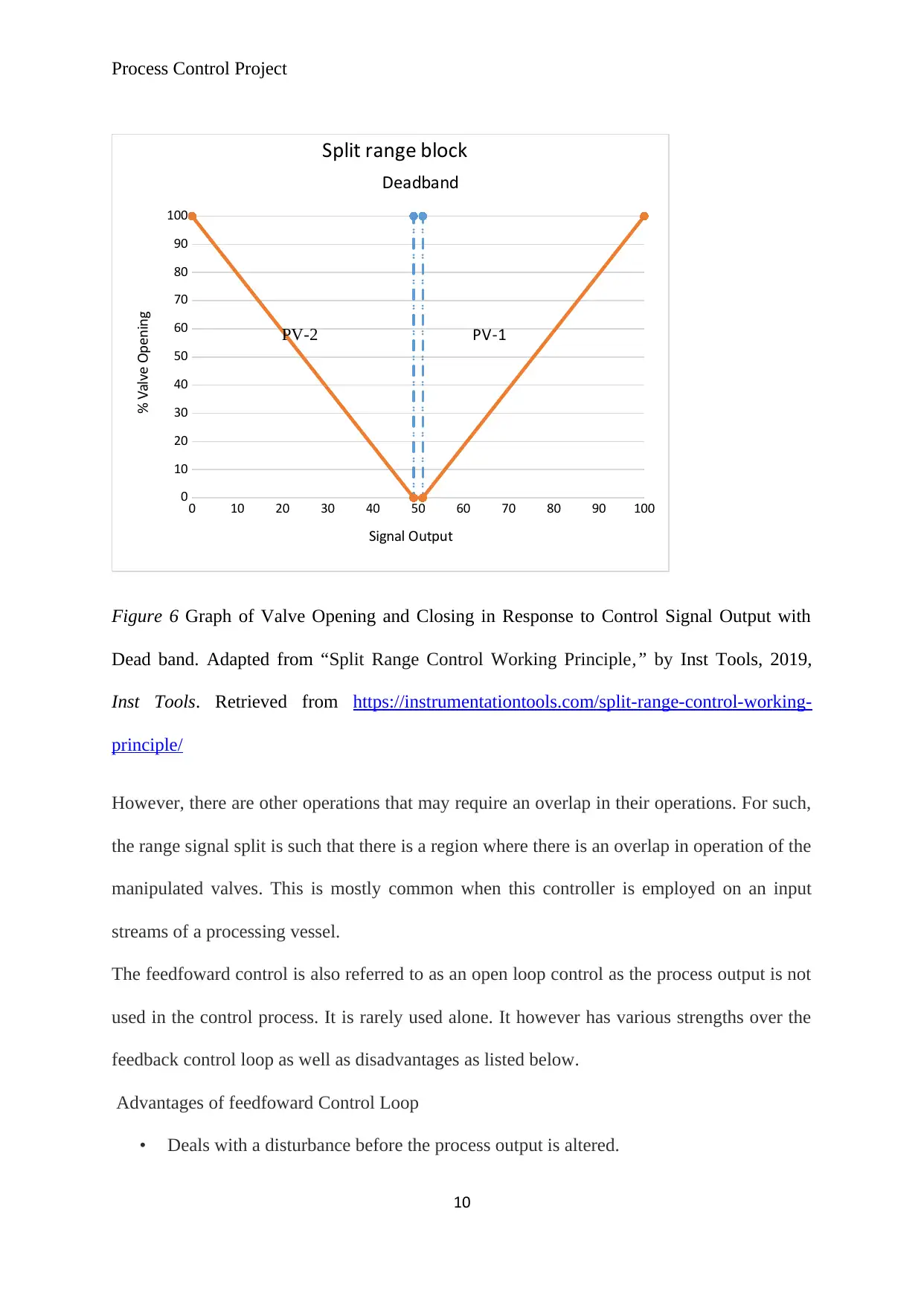
From the valve response in Valve Opening and Closing in Response to Controller Signal
Output. Adapted from “Split Range Control Working Principle,” by Inst Tools, 2019,Inst
Tools.. Retrieved April 18,2019, from https://instrumentationtools.com/split-range-control-
working-principle/ above, there is a continuous shift from the depressurizing phase to the
addition of fuel gas into the system when the controller’s output signal is at 50% of the output
signal. This causes a continuous oscillation in the between the two operations taking place in
the separator. To get rid of the continuity in oscillations, a dead band can be introduced such
that the response to the controller signal is divided into a 0-49% and 51-100%. The range
between 49% and 51% of the controller’s signal output allows for proper transition from one
valve closure to begin the opening of the other valve. This ensures better stability in the
controller system operation.
9
The pH controller gets a signal from the pH transmitter and changes the flow rate of lime
from the error between the pH measured and the established set-point. This process
constitutes the feedback control loop. In this case, the feedback is a negative feedback as the
action taken is to minimize the error caused by the disturbance or load added to the system,
which is lime for this example.
Discussion
From the valve response in Valve Opening and Closing in Response to Controller Signal
Output. Adapted from “Split Range Control Working Principle,” by Inst Tools, 2019,Inst
Tools.. Retrieved April 18,2019, from https://instrumentationtools.com/split-range-control-
working-principle/ above, there is a continuous shift from the depressurizing phase to the
addition of fuel gas into the system when the controller’s output signal is at 50% of the output
signal. This causes a continuous oscillation in the between the two operations taking place in
the separator. To get rid of the continuity in oscillations, a dead band can be introduced such
that the response to the controller signal is divided into a 0-49% and 51-100%. The range
between 49% and 51% of the controller’s signal output allows for proper transition from one
valve closure to begin the opening of the other valve. This ensures better stability in the
controller system operation.
9
⊘ This is a preview!⊘
Do you want full access?
Subscribe today to unlock all pages.
Trusted by 1+ million students worldwide
Process Control Project
0 10 20 30 40 50 60 70 80 90 100
0
10
20
30
40
50
60
70
80
90
100
Split range block
Signal Output
% Valve Opening
PV-2 PV-1
Deadband
Figure 6 Graph of Valve Opening and Closing in Response to Control Signal Output with
Dead band. Adapted from “Split Range Control Working Principle,” by Inst Tools, 2019,
Inst Tools. Retrieved from https://instrumentationtools.com/split-range-control-working-
principle/
However, there are other operations that may require an overlap in their operations. For such,
the range signal split is such that there is a region where there is an overlap in operation of the
manipulated valves. This is mostly common when this controller is employed on an input
streams of a processing vessel.
The feedfoward control is also referred to as an open loop control as the process output is not
used in the control process. It is rarely used alone. It however has various strengths over the
feedback control loop as well as disadvantages as listed below.
Advantages of feedfoward Control Loop
• Deals with a disturbance before the process output is altered.
10
Paraphrase This Document
Need a fresh take? Get an instant paraphrase of this document with our AI Paraphraser
Process Control Project
• The feedfowaard control system helps maintain the stability of the closed loop
response of the system that is, the response from the feedfoward control system is not
oscillatory.
Disadvantages of feedfoward Control Loop
• Cannot eliminate steady-state offset
• Compels the need of a sensor and model for individual load disturbance
• Requires high level of attention at the modelling stage to avoid errors in the system.
• The characteristics or behavior of the system towards changes brought about by a
disturbance should be clearly stated and the designers well versed with it for them to
design a suitable feedfoward control process for the said system.
The advantage of combining a feedfoward and feedback mechanism is the fact that the
disadvantages of the feedfoward are countered by the advantages of the feedback and vice
versa. As the feedback control aims at maintaining a steady pH, the feedfoward control works
to suppress feed flow rate disturbances. However, the feedfoward strategy may fail to
eliminate all disturbances in the system due to modelling errors. The feedback control tracks
the changes in the setpoints while limiting the unquantified disturbances in a non-ideal
process. Despite these control strategies working hand in hand, they are designed separately.
Generally, the feedback-feedfoward control combination gives the best process control. As
the open loop feedfoward improves a total of 90% offsets in the process, the remainder 10%
is adjusted by the bias bred by the feedback closed loop. This ensures that both the
feedfoward control is not worked beyond its capabilities while reducing the disturbance to be
handled by the feedback closed loop (Science Direct, 2019).
Conclusion
The use of appropriate control mechanisms are an important part of any chemical industry.
According to Sinnot (2005), controls help in increasing the efficiency of a plant operation
11
Process Control Project
hence saving in costs, ensuring the safety of personnel as well as equipment in a processing
plant, help in complying to standards and regulations set for the plant to operate in their
jurisdictions as well as help in goal accomplishment in an organization. It is therefore
important to study a process in order to understand the desired characteristics of the
operation, the inputs and the outputs and how to control them in order to implement an
efficient control mechanism.
12
⊘ This is a preview!⊘
Do you want full access?
Subscribe today to unlock all pages.
Trusted by 1+ million students worldwide
1 out of 13
Related Documents


Your All-in-One AI-Powered Toolkit for Academic Success.
+13062052269
info@desklib.com
Available 24*7 on WhatsApp / Email
![[object Object]](/_next/static/media/star-bottom.7253800d.svg)
Unlock your academic potential
Copyright © 2020–2026 A2Z Services. All Rights Reserved. Developed and managed by ZUCOL.