E-commerce Business LAN Design and Setup
VerifiedAdded on 2022/11/30
|24
|3396
|467
AI Summary
This project aims to implement a local area network design and setup for an e-commerce business. It includes hardware requirements, network diagram, logical diagram, IP addressing, routing protocol, and network security. The project will take two months to complete.
Contribute Materials
Your contribution can guide someone’s learning journey. Share your
documents today.
Project scope
It should be noted that every flourishing business enterprise today has embraced IT infrastructure into
its business processes. Reasons for this course are self-explanatory that well designed IT infrastructure
for organizations is the heart and center of all operations making business processes performed in an
efficient, effective and economical way. Hence, our e-commerce business is not an exception. The
stakeholders of this business wants a local area network design and setup that that will drive its e-
commerce business processes. This project implementation will take two months beginning the month
of June 1st, 2019.
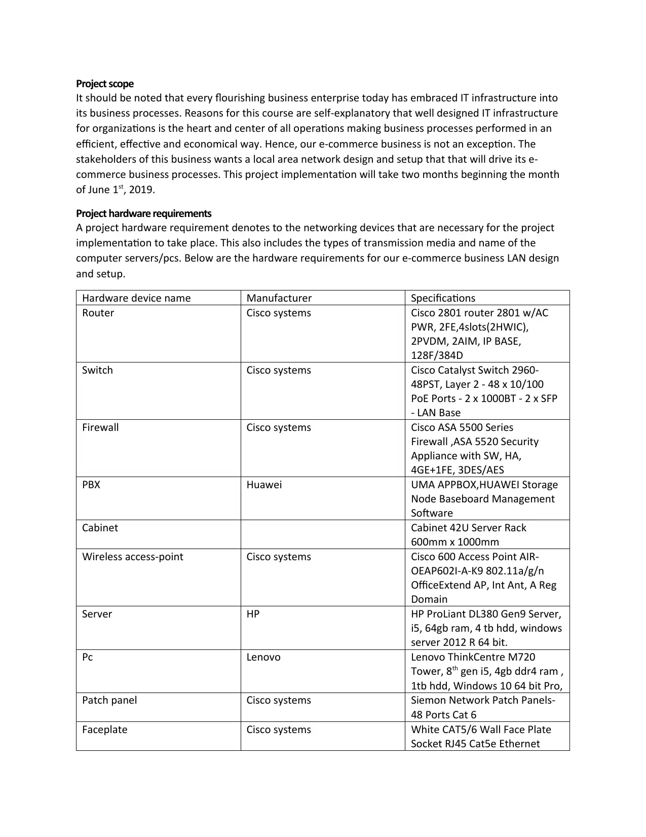
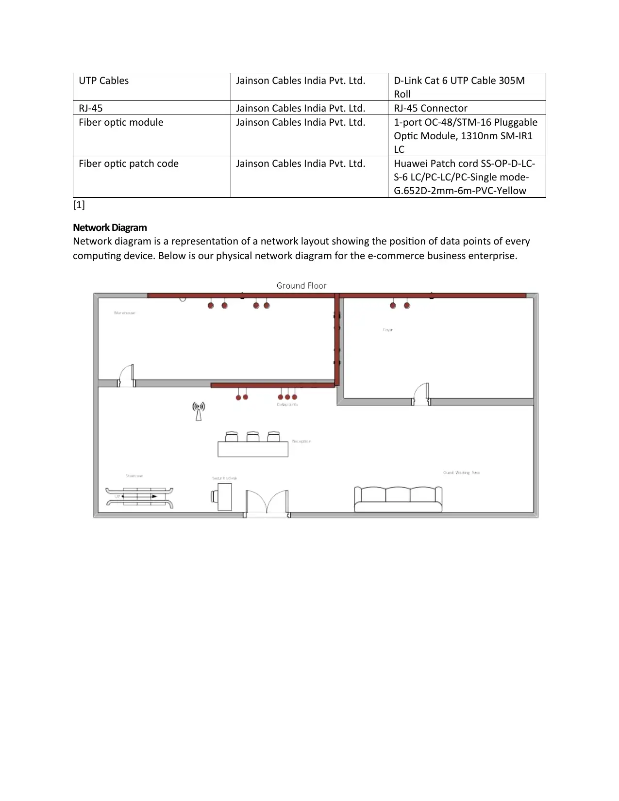
Project hardware requirements
A project hardware requirement denotes to the networking devices that are necessary for the project
implementation to take place. This also includes the types of transmission media and name of the
computer servers/pcs. Below are the hardware requirements for our e-commerce business LAN design
and setup.
Hardware device name Manufacturer Specifications
Router Cisco systems Cisco 2801 router 2801 w/AC
PWR, 2FE,4slots(2HWIC),
2PVDM, 2AIM, IP BASE,
128F/384D
Switch Cisco systems Cisco Catalyst Switch 2960-
48PST, Layer 2 - 48 x 10/100
PoE Ports - 2 x 1000BT - 2 x SFP
- LAN Base
Firewall Cisco systems Cisco ASA 5500 Series
Firewall ,ASA 5520 Security
Appliance with SW, HA,
4GE+1FE, 3DES/AES
PBX Huawei UMA APPBOX,HUAWEI Storage
Node Baseboard Management
Software
Cabinet Cabinet 42U Server Rack
600mm x 1000mm
Wireless access-point Cisco systems Cisco 600 Access Point AIR-
OEAP602I-A-K9 802.11a/g/n
OfficeExtend AP, Int Ant, A Reg
Domain
Server HP HP ProLiant DL380 Gen9 Server,
i5, 64gb ram, 4 tb hdd, windows
server 2012 R 64 bit.
Pc Lenovo Lenovo ThinkCentre M720
Tower, 8th gen i5, 4gb ddr4 ram ,
1tb hdd, Windows 10 64 bit Pro,
Patch panel Cisco systems Siemon Network Patch Panels-
48 Ports Cat 6
Faceplate Cisco systems White CAT5/6 Wall Face Plate
Socket RJ45 Cat5e Ethernet
Secure Best Marks with AI Grader
Need help grading? Try our AI Grader for instant feedback on your assignments.
UTP Cables Jainson Cables India Pvt. Ltd. D-Link Cat 6 UTP Cable 305M
Roll
RJ-45 Jainson Cables India Pvt. Ltd. RJ-45 Connector
Fiber optic module Jainson Cables India Pvt. Ltd. 1-port OC-48/STM-16 Pluggable
Optic Module, 1310nm SM-IR1
LC
Fiber optic patch code Jainson Cables India Pvt. Ltd. Huawei Patch cord SS-OP-D-LC-
S-6 LC/PC-LC/PC-Single mode-
G.652D-2mm-6m-PVC-Yellow
[1]
Network Diagram
Network diagram is a representation of a network layout showing the position of data points of every
computing device. Below is our physical network diagram for the e-commerce business enterprise.
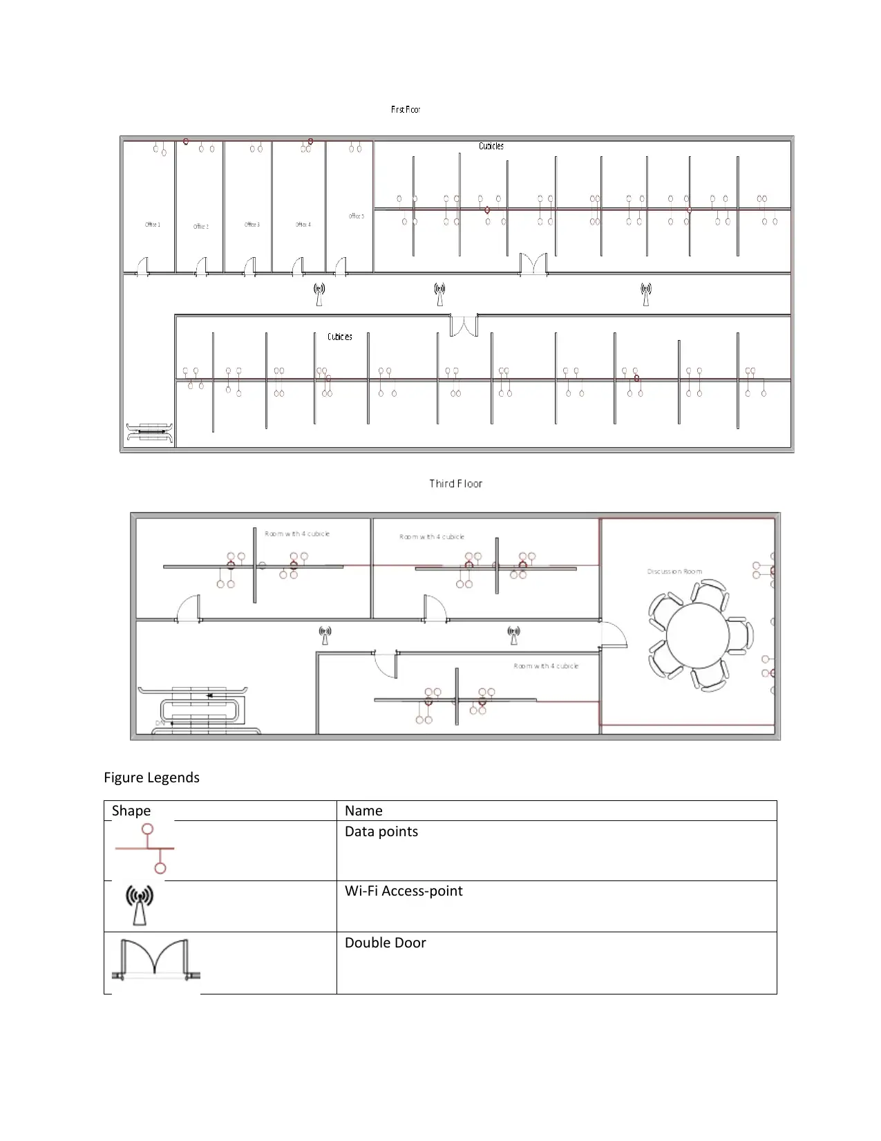
Figure Legends
Shape Name
Data points
Wi-Fi Access-point
Double Door
Shape Name
Data points
Wi-Fi Access-point
Double Door
Cubicle separated room
Single Door
Staircase
Floor assignment:
Ground Floor – there is a receptionist desk at the entrance. The desk is for the inquiry need of the
visitors that visit the premise. The lounge area is for the guests waiting for the service. Foyer and storage
rooms are also found on the ground floor.
First floor: this floor has five offices four of which are used as administrative offices and one used as IT
server room department. On this floor, there are forty cubicles used as the work flow.
Second floor – this is the topmost floor, it has a meeting room where all meetings are conducted. The
floor also has 3 rooms with 4 cubicles each which are the extended working area.
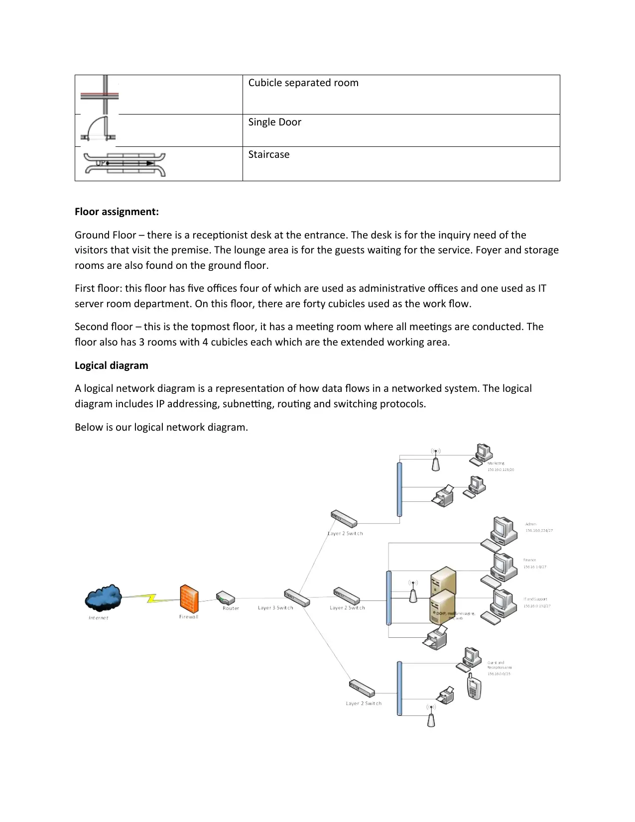
Logical diagram
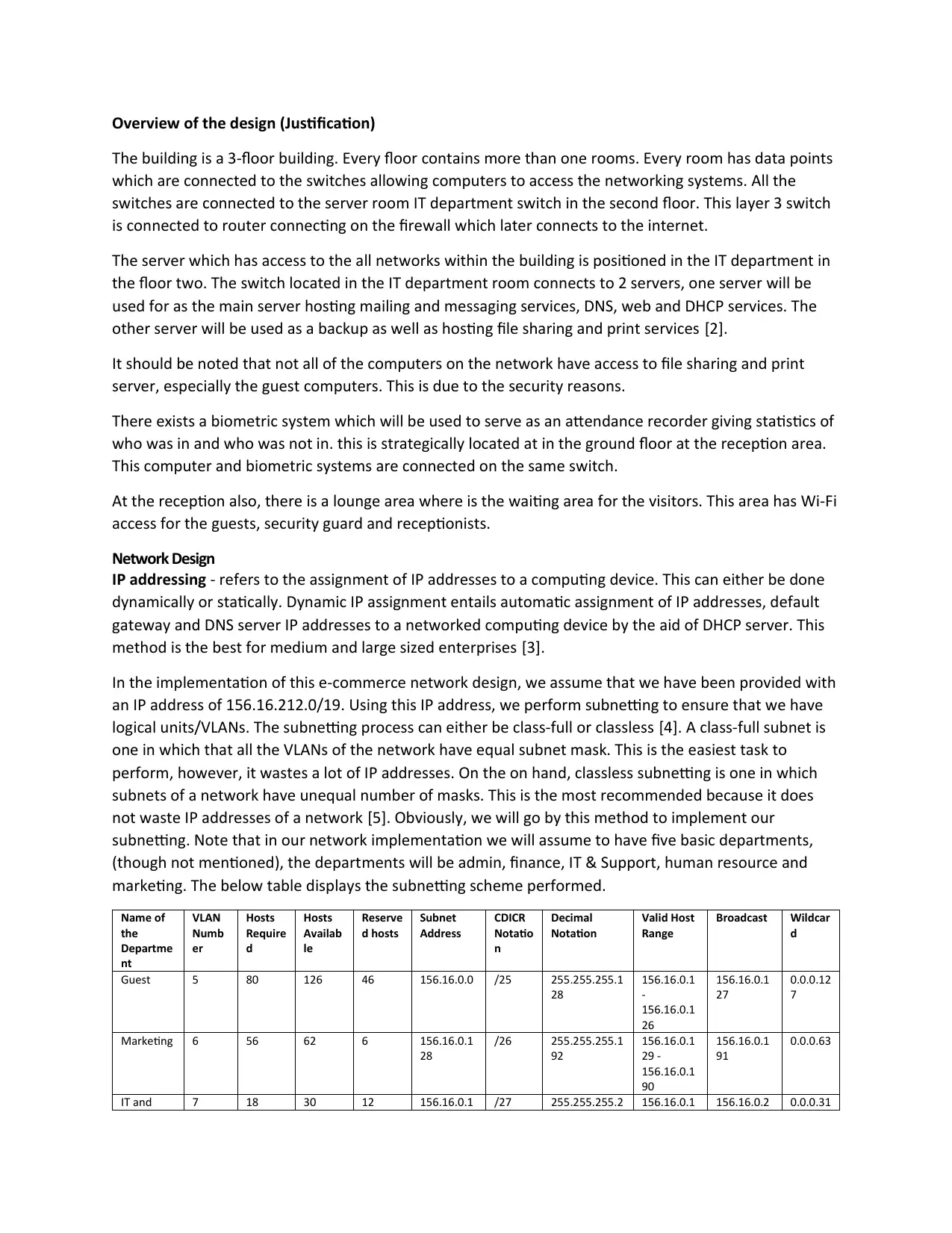
A logical network diagram is a representation of how data flows in a networked system. The logical
diagram includes IP addressing, subnetting, routing and switching protocols.
Below is our logical network diagram.
Secure Best Marks with AI Grader
Need help grading? Try our AI Grader for instant feedback on your assignments.
Overview of the design (Justification)
The building is a 3-floor building. Every floor contains more than one rooms. Every room has data points
which are connected to the switches allowing computers to access the networking systems. All the
switches are connected to the server room IT department switch in the second floor. This layer 3 switch
is connected to router connecting on the firewall which later connects to the internet.
The server which has access to the all networks within the building is positioned in the IT department in
the floor two. The switch located in the IT department room connects to 2 servers, one server will be
used for as the main server hosting mailing and messaging services, DNS, web and DHCP services. The
other server will be used as a backup as well as hosting file sharing and print services [2].
It should be noted that not all of the computers on the network have access to file sharing and print
server, especially the guest computers. This is due to the security reasons.
There exists a biometric system which will be used to serve as an attendance recorder giving statistics of
who was in and who was not in. this is strategically located at in the ground floor at the reception area.
This computer and biometric systems are connected on the same switch.
At the reception also, there is a lounge area where is the waiting area for the visitors. This area has Wi-Fi
access for the guests, security guard and receptionists.
Network Design
IP addressing - refers to the assignment of IP addresses to a computing device. This can either be done
dynamically or statically. Dynamic IP assignment entails automatic assignment of IP addresses, default
gateway and DNS server IP addresses to a networked computing device by the aid of DHCP server. This
method is the best for medium and large sized enterprises [3].
In the implementation of this e-commerce network design, we assume that we have been provided with
an IP address of 156.16.212.0/19. Using this IP address, we perform subnetting to ensure that we have
logical units/VLANs. The subnetting process can either be class-full or classless [4]. A class-full subnet is
one in which that all the VLANs of the network have equal subnet mask. This is the easiest task to
perform, however, it wastes a lot of IP addresses. On the on hand, classless subnetting is one in which
subnets of a network have unequal number of masks. This is the most recommended because it does
not waste IP addresses of a network [5]. Obviously, we will go by this method to implement our
subnetting. Note that in our network implementation we will assume to have five basic departments,
(though not mentioned), the departments will be admin, finance, IT & Support, human resource and
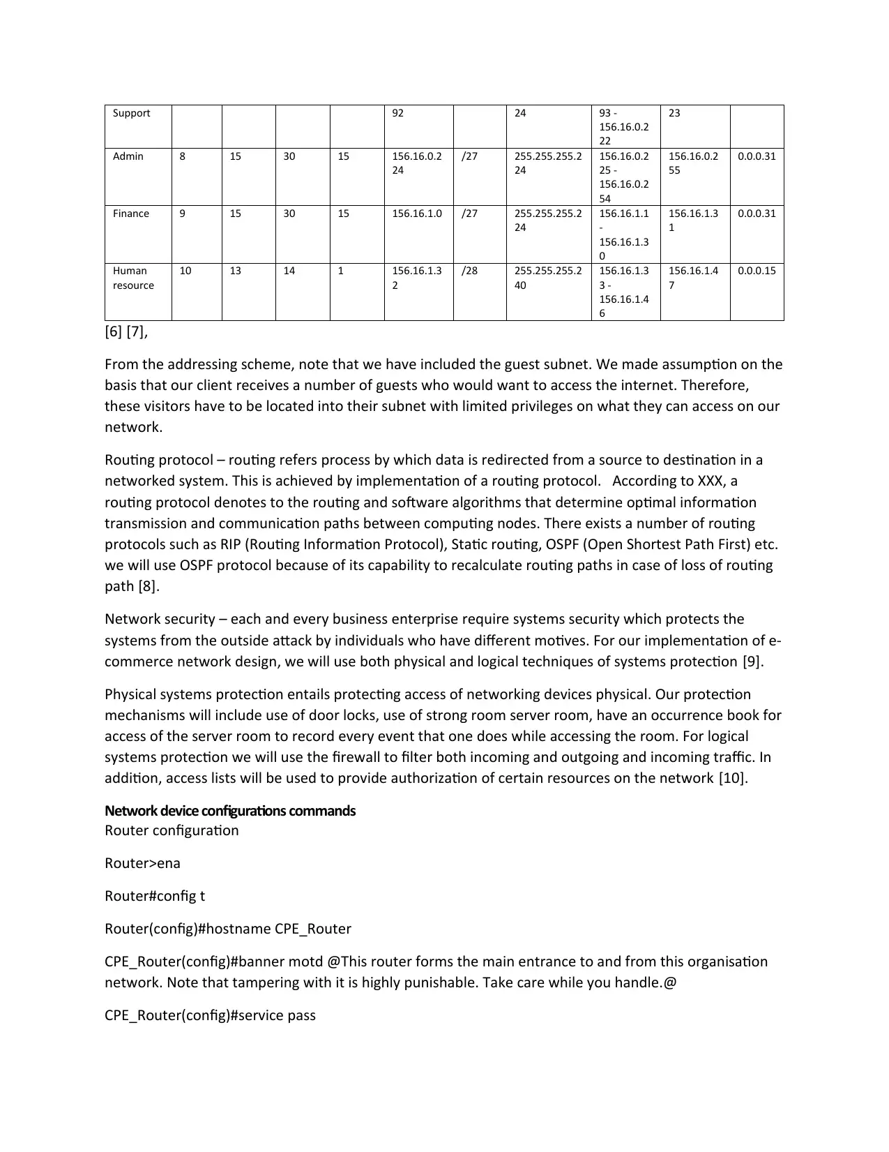
marketing. The below table displays the subnetting scheme performed.
Name of
the
Departme
nt
VLAN
Numb
er
Hosts
Require
d
Hosts
Availab
le
Reserve
d hosts
Subnet
Address
CDICR
Notatio
n
Decimal
Notation
Valid Host
Range
Broadcast Wildcar
d
Guest 5 80 126 46 156.16.0.0 /25 255.255.255.1
28
156.16.0.1
-
156.16.0.1
26
156.16.0.1
27
0.0.0.12
7
Marketing 6 56 62 6 156.16.0.1
28
/26 255.255.255.1
92
156.16.0.1
29 -
156.16.0.1
90
156.16.0.1
91
0.0.0.63
IT and 7 18 30 12 156.16.0.1 /27 255.255.255.2 156.16.0.1 156.16.0.2 0.0.0.31
Support 92 24 93 -
156.16.0.2
22
23
Admin 8 15 30 15 156.16.0.2
24
/27 255.255.255.2
24
156.16.0.2
25 -
156.16.0.2
54
156.16.0.2
55
0.0.0.31
Finance 9 15 30 15 156.16.1.0 /27 255.255.255.2
24
156.16.1.1
-
156.16.1.3
0
156.16.1.3
1
0.0.0.31
Human
resource
10 13 14 1 156.16.1.3
2
/28 255.255.255.2
40
156.16.1.3
3 -
156.16.1.4
6
156.16.1.4
7
0.0.0.15
[6] [7],
From the addressing scheme, note that we have included the guest subnet. We made assumption on the
basis that our client receives a number of guests who would want to access the internet. Therefore,
these visitors have to be located into their subnet with limited privileges on what they can access on our
network.
Routing protocol – routing refers process by which data is redirected from a source to destination in a
networked system. This is achieved by implementation of a routing protocol. According to XXX, a
routing protocol denotes to the routing and software algorithms that determine optimal information
transmission and communication paths between computing nodes. There exists a number of routing
protocols such as RIP (Routing Information Protocol), Static routing, OSPF (Open Shortest Path First) etc.
we will use OSPF protocol because of its capability to recalculate routing paths in case of loss of routing
path [8].
Network security – each and every business enterprise require systems security which protects the
systems from the outside attack by individuals who have different motives. For our implementation of e-
commerce network design, we will use both physical and logical techniques of systems protection [9].
Physical systems protection entails protecting access of networking devices physical. Our protection
mechanisms will include use of door locks, use of strong room server room, have an occurrence book for
access of the server room to record every event that one does while accessing the room. For logical
systems protection we will use the firewall to filter both incoming and outgoing and incoming traffic. In
addition, access lists will be used to provide authorization of certain resources on the network [10].
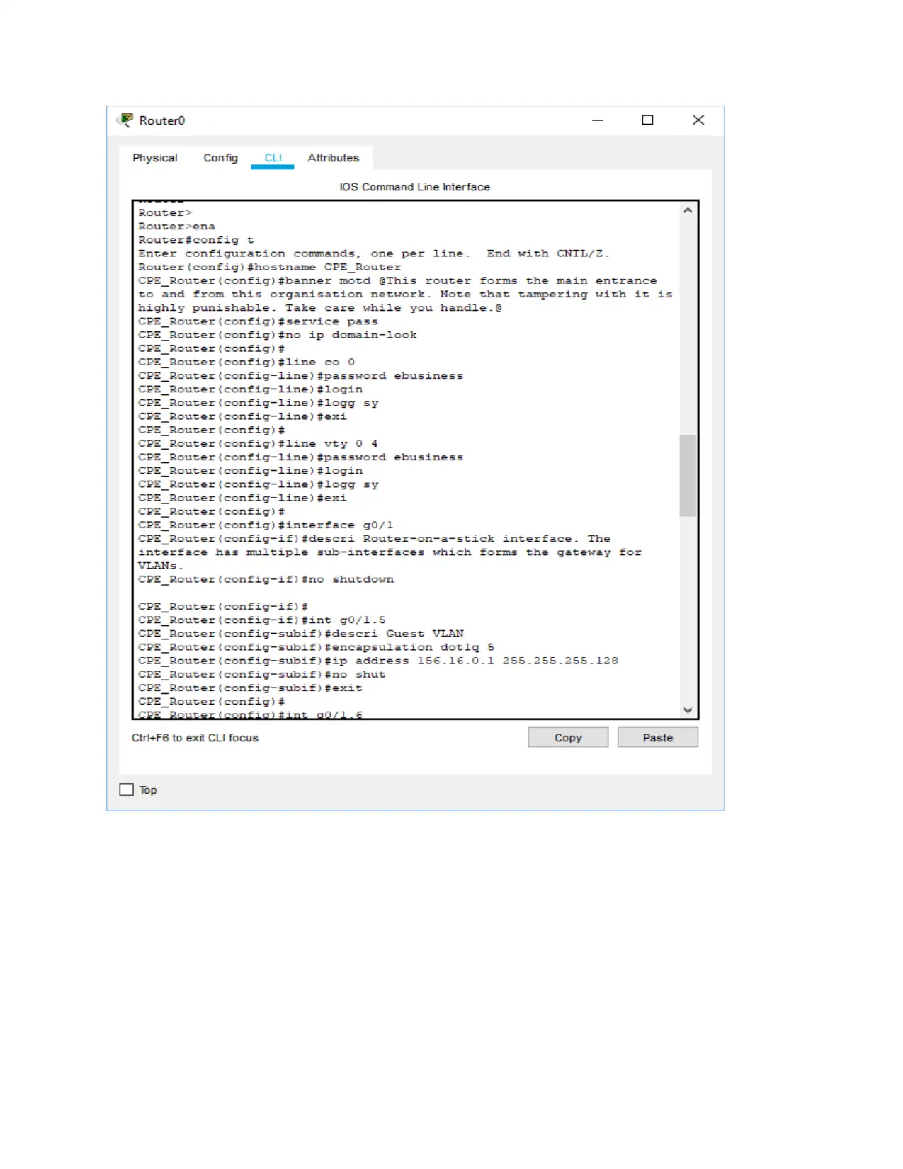
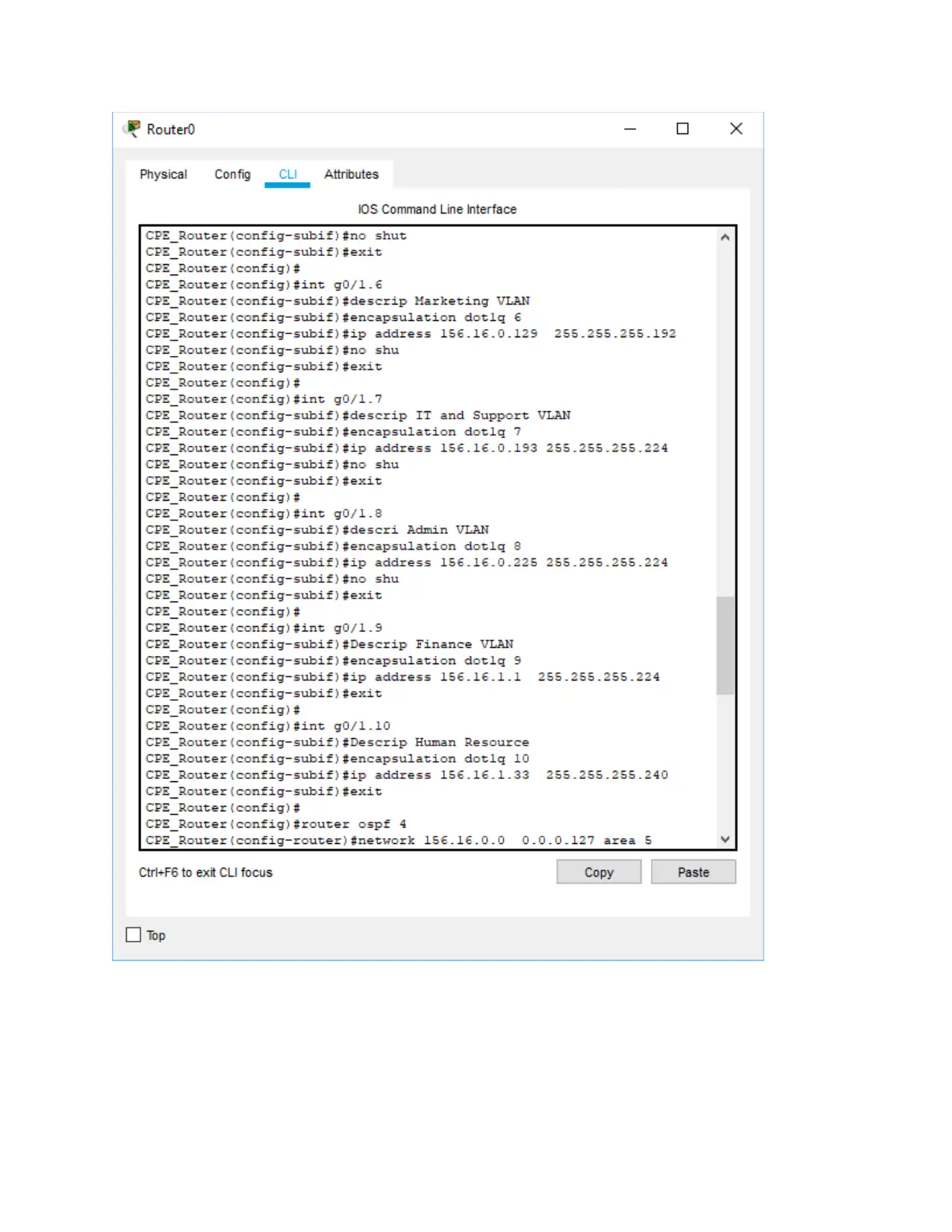
Network device configurations commands
Router configuration
Router>ena
Router#config t
Router(config)#hostname CPE_Router
CPE_Router(config)#banner motd @This router forms the main entrance to and from this organisation
network. Note that tampering with it is highly punishable. Take care while you handle.@
CPE_Router(config)#service pass
156.16.0.2
22
23
Admin 8 15 30 15 156.16.0.2
24
/27 255.255.255.2
24
156.16.0.2
25 -
156.16.0.2
54
156.16.0.2
55
0.0.0.31
Finance 9 15 30 15 156.16.1.0 /27 255.255.255.2
24
156.16.1.1
-
156.16.1.3
0
156.16.1.3
1
0.0.0.31
Human
resource
10 13 14 1 156.16.1.3
2
/28 255.255.255.2
40
156.16.1.3
3 -
156.16.1.4
6
156.16.1.4
7
0.0.0.15
[6] [7],
From the addressing scheme, note that we have included the guest subnet. We made assumption on the
basis that our client receives a number of guests who would want to access the internet. Therefore,
these visitors have to be located into their subnet with limited privileges on what they can access on our
network.
Routing protocol – routing refers process by which data is redirected from a source to destination in a
networked system. This is achieved by implementation of a routing protocol. According to XXX, a
routing protocol denotes to the routing and software algorithms that determine optimal information
transmission and communication paths between computing nodes. There exists a number of routing
protocols such as RIP (Routing Information Protocol), Static routing, OSPF (Open Shortest Path First) etc.
we will use OSPF protocol because of its capability to recalculate routing paths in case of loss of routing
path [8].
Network security – each and every business enterprise require systems security which protects the
systems from the outside attack by individuals who have different motives. For our implementation of e-
commerce network design, we will use both physical and logical techniques of systems protection [9].
Physical systems protection entails protecting access of networking devices physical. Our protection
mechanisms will include use of door locks, use of strong room server room, have an occurrence book for
access of the server room to record every event that one does while accessing the room. For logical
systems protection we will use the firewall to filter both incoming and outgoing and incoming traffic. In
addition, access lists will be used to provide authorization of certain resources on the network [10].
Network device configurations commands
Router configuration
Router>ena
Router#config t
Router(config)#hostname CPE_Router
CPE_Router(config)#banner motd @This router forms the main entrance to and from this organisation
network. Note that tampering with it is highly punishable. Take care while you handle.@
CPE_Router(config)#service pass

CPE_Router(config)#no ip domain-look
CPE_Router(config)#
CPE_Router(config)#line co 0
CPE_Router(config-line)#password ebusiness
CPE_Router(config-line)#login
CPE_Router(config-line)#logg sy
CPE_Router(config-line)#exi
CPE_Router(config)#
CPE_Router(config)#line vty 0 4
CPE_Router(config-line)#password ebusiness
CPE_Router(config-line)#login
CPE_Router(config-line)#logg sy
CPE_Router(config-line)#exi
CPE_Router(config)#
CPE_Router(config)#interface g0/1
CPE_Router(config-if)#descri Router-on-a-stick interface. The interface has multiple sub-interfaces which
forms the gateway for VLANs.
CPE_Router(config-if)#no shutdown
CPE_Router(config-if)#
CPE_Router(config-if)#int g0/1.5
CPE_Router(config-subif)#descri Guest VLAN
CPE_Router(config-subif)#encapsulation dot1q 5
CPE_Router(config-subif)#ip address 156.16.0.1 255.255.255.128
CPE_Router(config-subif)#no shut
CPE_Router(config-subif)#exit
CPE_Router(config)#
CPE_Router(config)#int g0/1.6
CPE_Router(config-subif)#descrip Marketing VLAN
CPE_Router(config-subif)#encapsulation dot1q 6
CPE_Router(config)#
CPE_Router(config)#line co 0
CPE_Router(config-line)#password ebusiness
CPE_Router(config-line)#login
CPE_Router(config-line)#logg sy
CPE_Router(config-line)#exi
CPE_Router(config)#
CPE_Router(config)#line vty 0 4
CPE_Router(config-line)#password ebusiness
CPE_Router(config-line)#login
CPE_Router(config-line)#logg sy
CPE_Router(config-line)#exi
CPE_Router(config)#
CPE_Router(config)#interface g0/1
CPE_Router(config-if)#descri Router-on-a-stick interface. The interface has multiple sub-interfaces which
forms the gateway for VLANs.
CPE_Router(config-if)#no shutdown
CPE_Router(config-if)#
CPE_Router(config-if)#int g0/1.5
CPE_Router(config-subif)#descri Guest VLAN
CPE_Router(config-subif)#encapsulation dot1q 5
CPE_Router(config-subif)#ip address 156.16.0.1 255.255.255.128
CPE_Router(config-subif)#no shut
CPE_Router(config-subif)#exit
CPE_Router(config)#
CPE_Router(config)#int g0/1.6
CPE_Router(config-subif)#descrip Marketing VLAN
CPE_Router(config-subif)#encapsulation dot1q 6
Paraphrase This Document
Need a fresh take? Get an instant paraphrase of this document with our AI Paraphraser

CPE_Router(config-subif)#ip address 156.16.0.129 255.255.255.192
CPE_Router(config-subif)#no shu
CPE_Router(config-subif)#exit
CPE_Router(config)#
CPE_Router(config)#int g0/1.7
CPE_Router(config-subif)#descrip IT and Support VLAN
CPE_Router(config-subif)#encapsulation dot1q 7
CPE_Router(config-subif)#ip address 156.16.0.193 255.255.255.224
CPE_Router(config-subif)#no shu
CPE_Router(config-subif)#exit
CPE_Router(config)#
CPE_Router(config)#int g0/1.8
CPE_Router(config-subif)#descri Admin VLAN
CPE_Router(config-subif)#encapsulation dot1q 8
CPE_Router(config-subif)#ip address 156.16.0.225 255.255.255.224
CPE_Router(config-subif)#no shu
CPE_Router(config-subif)#exit
CPE_Router(config)#
CPE_Router(config)#int g0/1.9
CPE_Router(config-subif)#Descrip Finance VLAN
CPE_Router(config-subif)#encapsulation dot1q 9
CPE_Router(config-subif)#ip address 156.16.1.1 255.255.255.224
CPE_Router(config-subif)#exit
CPE_Router(config)#
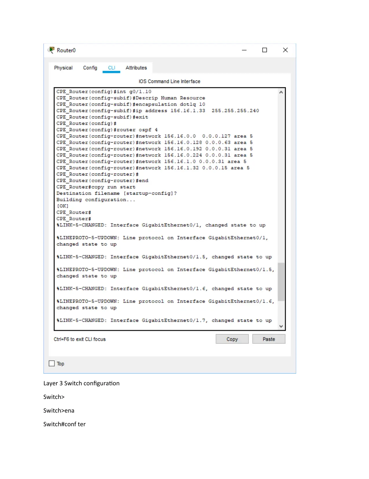
CPE_Router(config)#int g0/1.10
CPE_Router(config-subif)#Descrip Human Resource
CPE_Router(config-subif)#encapsulation dot1q 10
CPE_Router(config-subif)#ip address 156.16.1.33 255.255.255.240
CPE_Router(config-subif)#exit
CPE_Router(config-subif)#no shu
CPE_Router(config-subif)#exit
CPE_Router(config)#
CPE_Router(config)#int g0/1.7
CPE_Router(config-subif)#descrip IT and Support VLAN
CPE_Router(config-subif)#encapsulation dot1q 7
CPE_Router(config-subif)#ip address 156.16.0.193 255.255.255.224
CPE_Router(config-subif)#no shu
CPE_Router(config-subif)#exit
CPE_Router(config)#
CPE_Router(config)#int g0/1.8
CPE_Router(config-subif)#descri Admin VLAN
CPE_Router(config-subif)#encapsulation dot1q 8
CPE_Router(config-subif)#ip address 156.16.0.225 255.255.255.224
CPE_Router(config-subif)#no shu
CPE_Router(config-subif)#exit
CPE_Router(config)#
CPE_Router(config)#int g0/1.9
CPE_Router(config-subif)#Descrip Finance VLAN
CPE_Router(config-subif)#encapsulation dot1q 9
CPE_Router(config-subif)#ip address 156.16.1.1 255.255.255.224
CPE_Router(config-subif)#exit
CPE_Router(config)#
CPE_Router(config)#int g0/1.10
CPE_Router(config-subif)#Descrip Human Resource
CPE_Router(config-subif)#encapsulation dot1q 10
CPE_Router(config-subif)#ip address 156.16.1.33 255.255.255.240
CPE_Router(config-subif)#exit

CPE_Router(config)#
CPE_Router(config)#router ospf 4
CPE_Router(config-router)#network 156.16.0.0 0.0.0.127 area 5
CPE_Router(config-router)#network 156.16.0.128 0.0.0.63 area 5
CPE_Router(config-router)#network 156.16.0.192 0.0.0.31 area 5
CPE_Router(config-router)#network 156.16.0.224 0.0.0.31 area 5
CPE_Router(config-router)#network 156.16.1.0 0.0.0.31 area 5
CPE_Router(config-router)#network 156.16.1.32 0.0.0.15 area 5
CPE_Router(config-router)#
CPE_Router(config-router)#end
CPE_Router#copy run start
CPE_Router#
[4]
Secure Best Marks with AI Grader
Need help grading? Try our AI Grader for instant feedback on your assignments.
Layer 3 Switch configuration
Switch>
Switch>ena
Switch#conf ter
Switch>
Switch>ena
Switch#conf ter
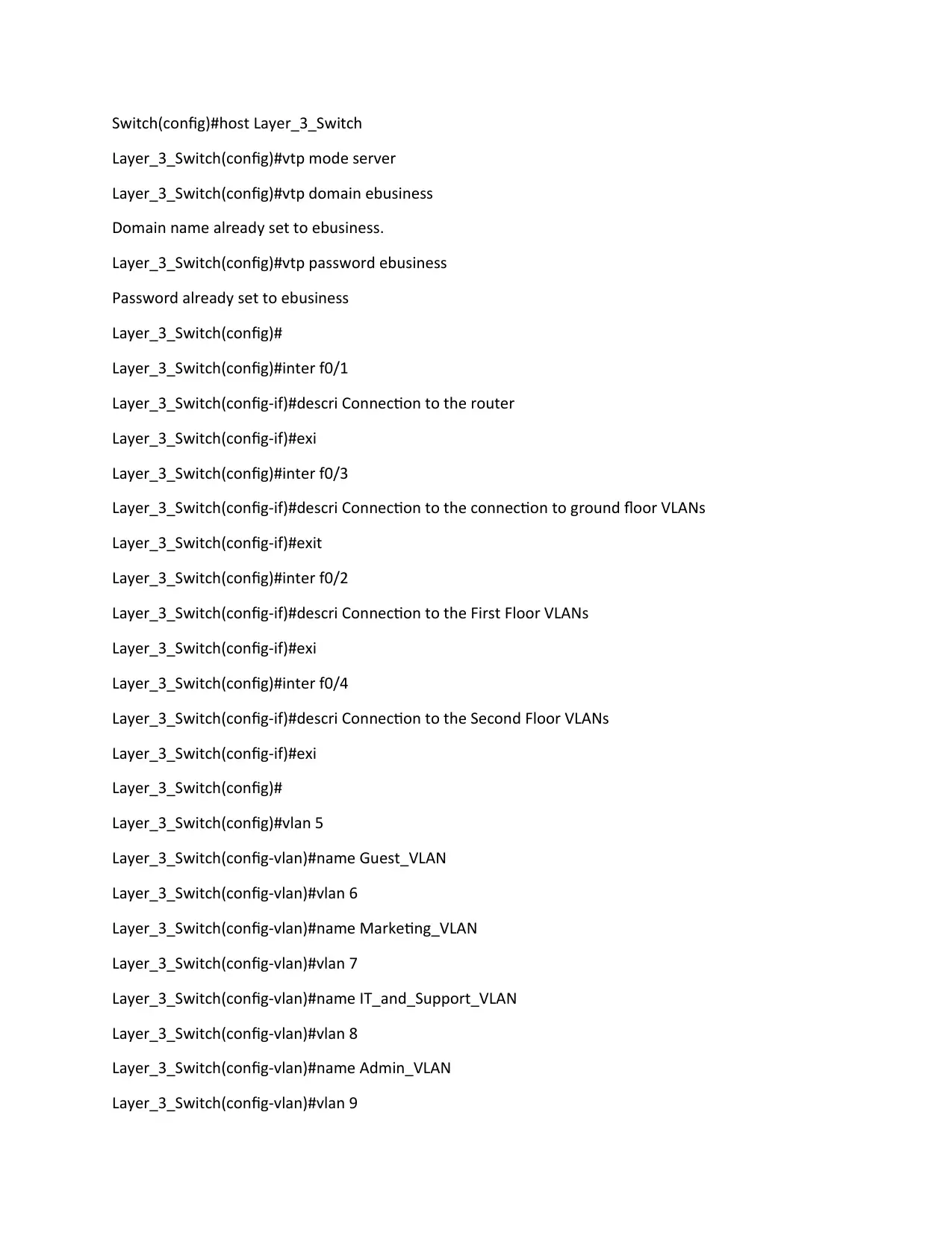
Switch(config)#host Layer_3_Switch
Layer_3_Switch(config)#vtp mode server
Layer_3_Switch(config)#vtp domain ebusiness
Domain name already set to ebusiness.
Layer_3_Switch(config)#vtp password ebusiness
Password already set to ebusiness
Layer_3_Switch(config)#
Layer_3_Switch(config)#inter f0/1
Layer_3_Switch(config-if)#descri Connection to the router
Layer_3_Switch(config-if)#exi
Layer_3_Switch(config)#inter f0/3
Layer_3_Switch(config-if)#descri Connection to the connection to ground floor VLANs
Layer_3_Switch(config-if)#exit
Layer_3_Switch(config)#inter f0/2
Layer_3_Switch(config-if)#descri Connection to the First Floor VLANs
Layer_3_Switch(config-if)#exi
Layer_3_Switch(config)#inter f0/4
Layer_3_Switch(config-if)#descri Connection to the Second Floor VLANs
Layer_3_Switch(config-if)#exi
Layer_3_Switch(config)#
Layer_3_Switch(config)#vlan 5
Layer_3_Switch(config-vlan)#name Guest_VLAN
Layer_3_Switch(config-vlan)#vlan 6
Layer_3_Switch(config-vlan)#name Marketing_VLAN
Layer_3_Switch(config-vlan)#vlan 7
Layer_3_Switch(config-vlan)#name IT_and_Support_VLAN
Layer_3_Switch(config-vlan)#vlan 8
Layer_3_Switch(config-vlan)#name Admin_VLAN
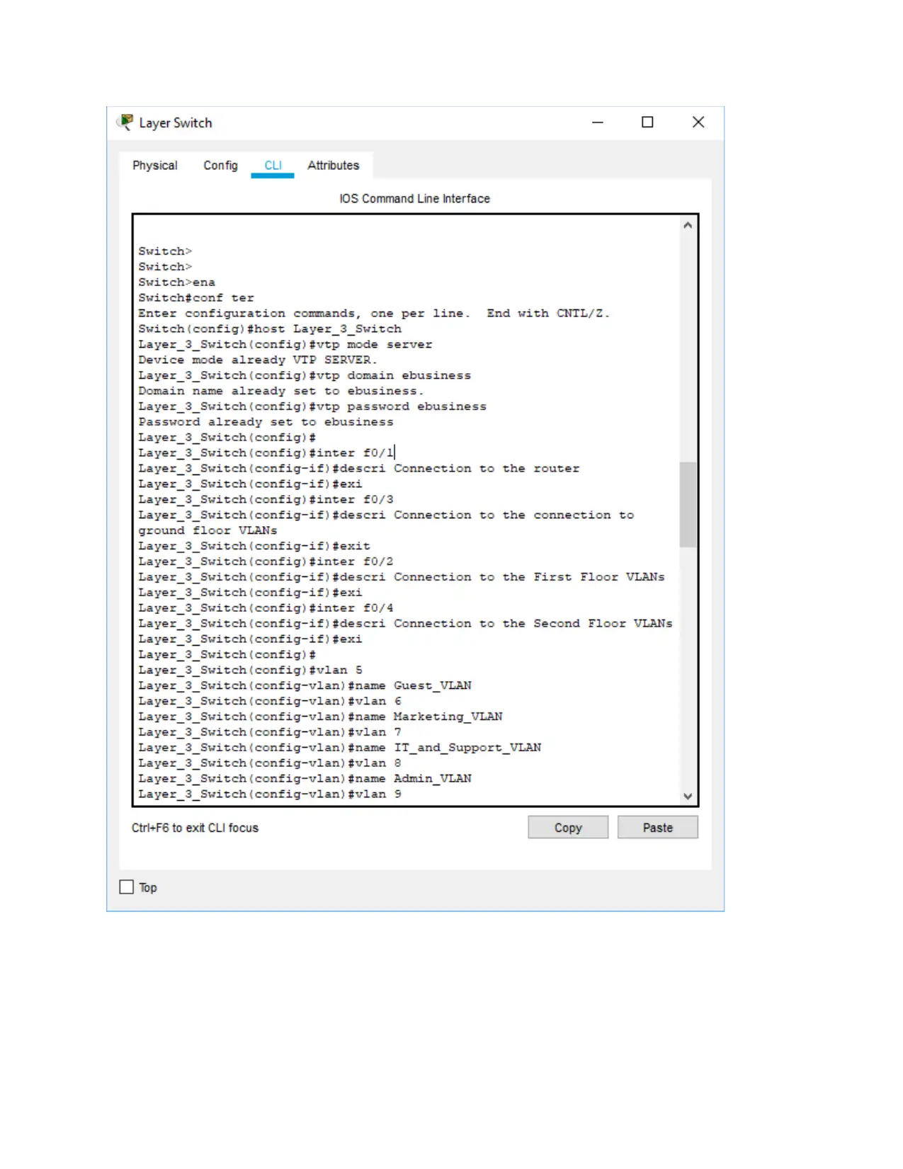
Layer_3_Switch(config-vlan)#vlan 9
Paraphrase This Document
Need a fresh take? Get an instant paraphrase of this document with our AI Paraphraser

Layer_3_Switch(config-vlan)#name Finance_VLAN
Layer_3_Switch(config-vlan)#vlan 10
Layer_3_Switch(config-vlan)#name Human_Resource_VLAN
Layer_3_Switch(config-vlan)#exit
Layer_3_Switch(config)#int range fa0/1-4
Layer_3_Switch(config-if-range)#switchport mode trunk
Layer_3_Switch(config-if-range)#inter range fa0/5-24
Layer_3_Switch(config-if-range)#shutdown
End
Copy run start
[11]
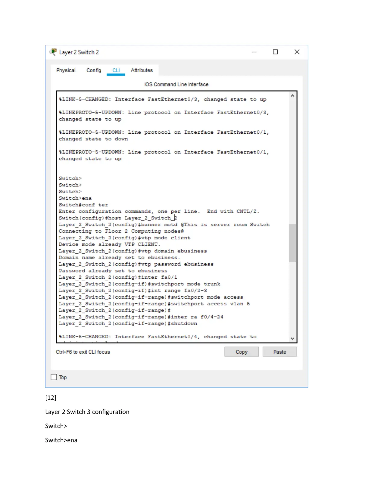
Layer 2 Switch 2 configuration
Switch>
Switch>ena
Switch#conf ter
Switch>
Switch>ena
Switch#conf ter
Secure Best Marks with AI Grader
Need help grading? Try our AI Grader for instant feedback on your assignments.
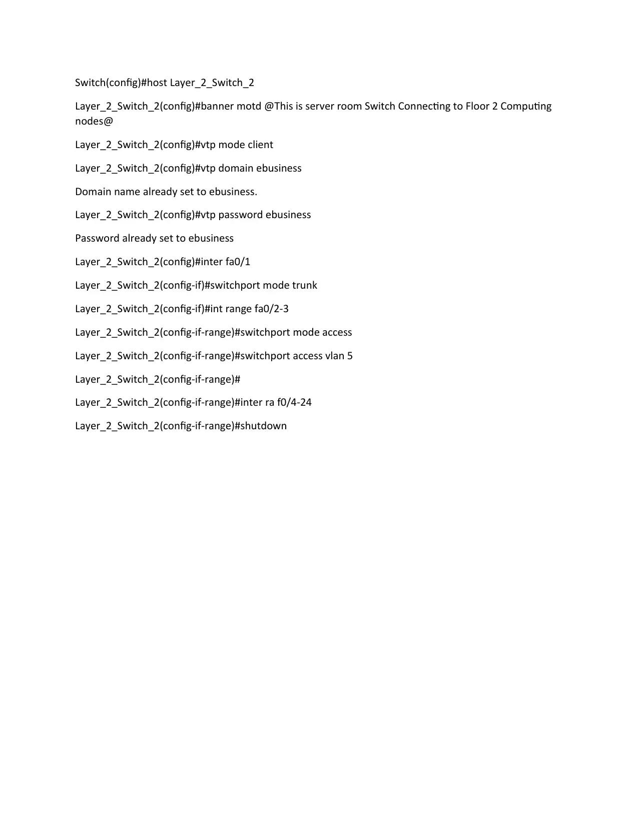
Switch(config)#host Layer_2_Switch_2
Layer_2_Switch_2(config)#banner motd @This is server room Switch Connecting to Floor 2 Computing
nodes@
Layer_2_Switch_2(config)#vtp mode client
Layer_2_Switch_2(config)#vtp domain ebusiness
Domain name already set to ebusiness.
Layer_2_Switch_2(config)#vtp password ebusiness
Password already set to ebusiness
Layer_2_Switch_2(config)#inter fa0/1
Layer_2_Switch_2(config-if)#switchport mode trunk
Layer_2_Switch_2(config-if)#int range fa0/2-3
Layer_2_Switch_2(config-if-range)#switchport mode access
Layer_2_Switch_2(config-if-range)#switchport access vlan 5
Layer_2_Switch_2(config-if-range)#
Layer_2_Switch_2(config-if-range)#inter ra f0/4-24
Layer_2_Switch_2(config-if-range)#shutdown
[12]
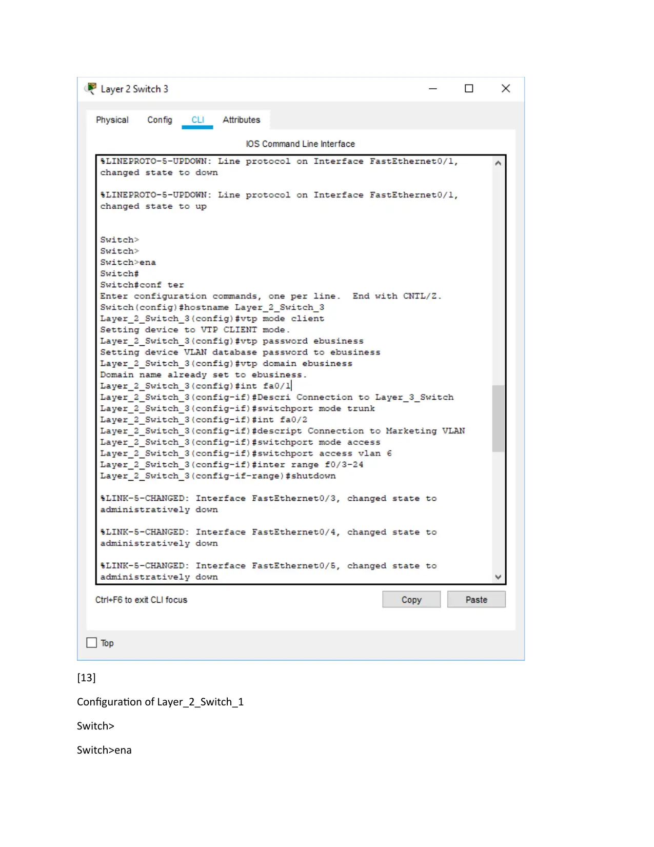
Layer 2 Switch 3 configuration
Switch>
Switch>ena
Layer 2 Switch 3 configuration
Switch>
Switch>ena
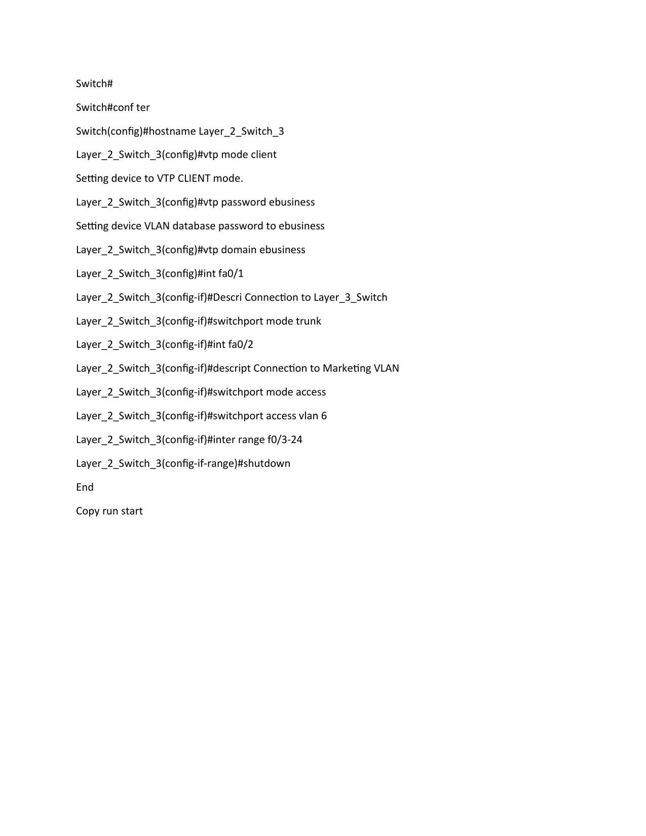
Switch#
Switch#conf ter
Switch(config)#hostname Layer_2_Switch_3
Layer_2_Switch_3(config)#vtp mode client
Setting device to VTP CLIENT mode.
Layer_2_Switch_3(config)#vtp password ebusiness
Setting device VLAN database password to ebusiness
Layer_2_Switch_3(config)#vtp domain ebusiness
Layer_2_Switch_3(config)#int fa0/1
Layer_2_Switch_3(config-if)#Descri Connection to Layer_3_Switch
Layer_2_Switch_3(config-if)#switchport mode trunk
Layer_2_Switch_3(config-if)#int fa0/2
Layer_2_Switch_3(config-if)#descript Connection to Marketing VLAN
Layer_2_Switch_3(config-if)#switchport mode access
Layer_2_Switch_3(config-if)#switchport access vlan 6
Layer_2_Switch_3(config-if)#inter range f0/3-24
Layer_2_Switch_3(config-if-range)#shutdown
End
Copy run start
Paraphrase This Document
Need a fresh take? Get an instant paraphrase of this document with our AI Paraphraser
[13]
Configuration of Layer_2_Switch_1
Switch>
Switch>ena
Configuration of Layer_2_Switch_1
Switch>
Switch>ena
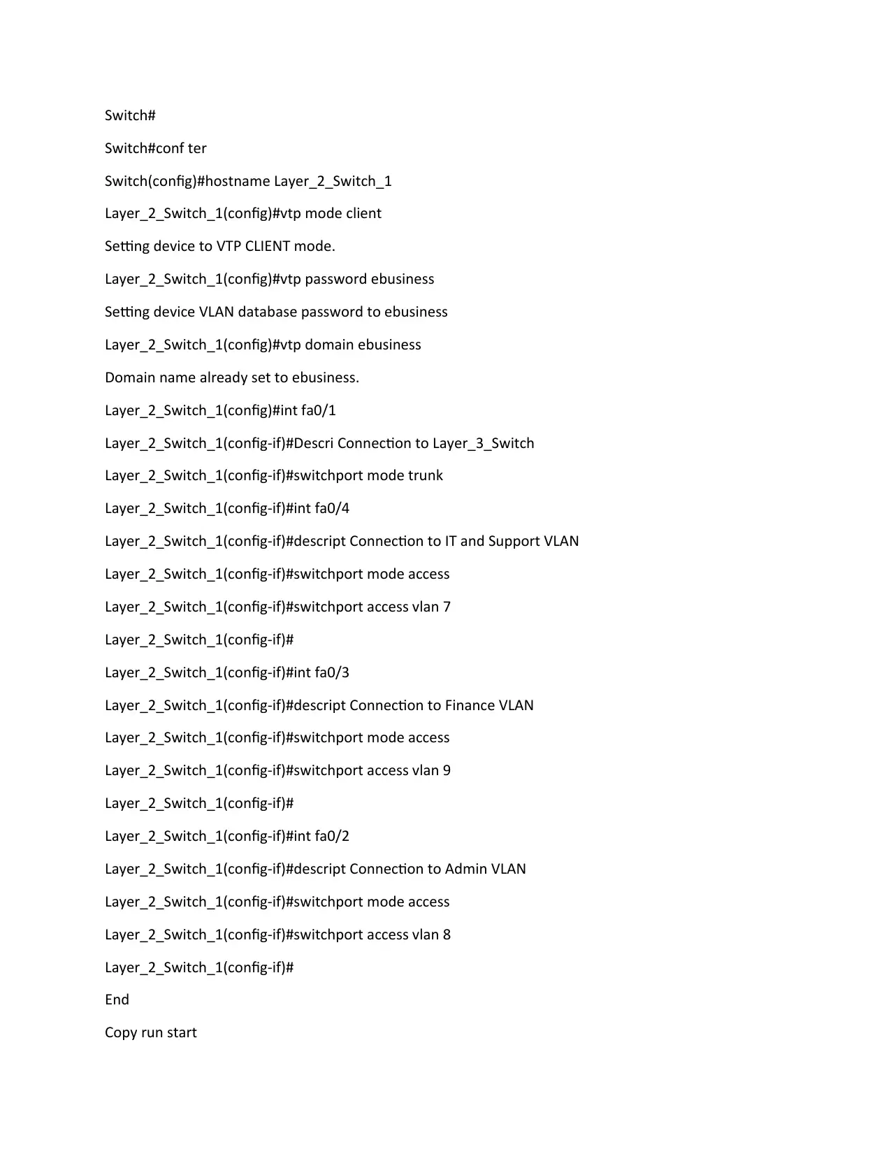
Switch#
Switch#conf ter
Switch(config)#hostname Layer_2_Switch_1
Layer_2_Switch_1(config)#vtp mode client
Setting device to VTP CLIENT mode.
Layer_2_Switch_1(config)#vtp password ebusiness
Setting device VLAN database password to ebusiness
Layer_2_Switch_1(config)#vtp domain ebusiness
Domain name already set to ebusiness.
Layer_2_Switch_1(config)#int fa0/1
Layer_2_Switch_1(config-if)#Descri Connection to Layer_3_Switch
Layer_2_Switch_1(config-if)#switchport mode trunk
Layer_2_Switch_1(config-if)#int fa0/4
Layer_2_Switch_1(config-if)#descript Connection to IT and Support VLAN
Layer_2_Switch_1(config-if)#switchport mode access
Layer_2_Switch_1(config-if)#switchport access vlan 7
Layer_2_Switch_1(config-if)#
Layer_2_Switch_1(config-if)#int fa0/3
Layer_2_Switch_1(config-if)#descript Connection to Finance VLAN
Layer_2_Switch_1(config-if)#switchport mode access
Layer_2_Switch_1(config-if)#switchport access vlan 9
Layer_2_Switch_1(config-if)#
Layer_2_Switch_1(config-if)#int fa0/2
Layer_2_Switch_1(config-if)#descript Connection to Admin VLAN
Layer_2_Switch_1(config-if)#switchport mode access
Layer_2_Switch_1(config-if)#switchport access vlan 8
Layer_2_Switch_1(config-if)#
End
Copy run start
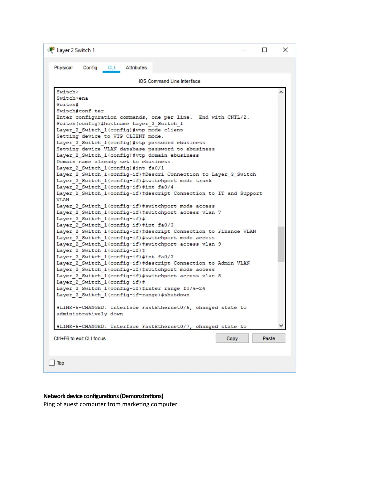
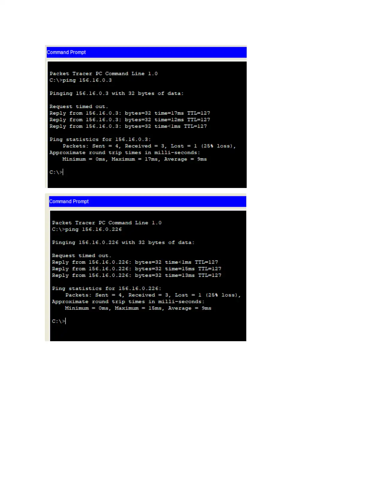
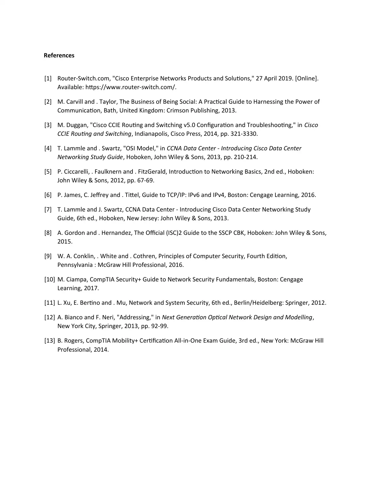
Network device configurations (Demonstrations)
Ping of guest computer from marketing computer
Ping of guest computer from marketing computer
Secure Best Marks with AI Grader
Need help grading? Try our AI Grader for instant feedback on your assignments.
References
[1] Router-Switch.com, "Cisco Enterprise Networks Products and Solutions," 27 April 2019. [Online].
Available: https://www.router-switch.com/.
[2] M. Carvill and . Taylor, The Business of Being Social: A Practical Guide to Harnessing the Power of
Communication, Bath, United Kingdom: Crimson Publishing, 2013.
[3] M. Duggan, "Cisco CCIE Routing and Switching v5.0 Configuration and Troubleshooting," in Cisco
CCIE Routing and Switching, Indianapolis, Cisco Press, 2014, pp. 321-3330.
[4] T. Lammle and . Swartz, "OSI Model," in CCNA Data Center - Introducing Cisco Data Center
Networking Study Guide, Hoboken, John Wiley & Sons, 2013, pp. 210-214.
[5] P. Ciccarelli, . Faulknern and . FitzGerald, Introduction to Networking Basics, 2nd ed., Hoboken:
John Wiley & Sons, 2012, pp. 67-69.
[6] P. James, C. Jeffrey and . Tittel, Guide to TCP/IP: IPv6 and IPv4, Boston: Cengage Learning, 2016.
[7] T. Lammle and J. Swartz, CCNA Data Center - Introducing Cisco Data Center Networking Study
Guide, 6th ed., Hoboken, New Jersey: John Wiley & Sons, 2013.
[8] A. Gordon and . Hernandez, The Official (ISC)2 Guide to the SSCP CBK, Hoboken: John Wiley & Sons,
2015.
[9] W. A. Conklin, . White and . Cothren, Principles of Computer Security, Fourth Edition,
Pennsylvania : McGraw Hill Professional, 2016.
[10] M. Ciampa, CompTIA Security+ Guide to Network Security Fundamentals, Boston: Cengage
Learning, 2017.
[11] L. Xu, E. Bertino and . Mu, Network and System Security, 6th ed., Berlin/Heidelberg: Springer, 2012.
[12] A. Bianco and F. Neri, "Addressing," in Next Generation Optical Network Design and Modelling,
New York City, Springer, 2013, pp. 92-99.
[13] B. Rogers, CompTIA Mobility+ Certification All-in-One Exam Guide, 3rd ed., New York: McGraw Hill
Professional, 2014.
1 out of 24
Your All-in-One AI-Powered Toolkit for Academic Success.
+13062052269
info@desklib.com
Available 24*7 on WhatsApp / Email
![[object Object]](/_next/static/media/star-bottom.7253800d.svg)
Unlock your academic potential
© 2024 | Zucol Services PVT LTD | All rights reserved.

