Part 2 Report: Instrumentation, PID Control, Feedback Loops Analysis
VerifiedAdded on 2022/08/27
|16
|3284
|29
Report
AI Summary
This report provides a comprehensive overview of PID (Proportional-Integral-Derivative) controllers, detailing their proportional, integral, and derivative components and their roles in controlling motor speed and minimizing errors like overshoot and undershoot. It explores feedback loops, including negative and positive types, and their applications in instrumentation and temperature control. The report also examines the impact of IoT on instrumentation, including its applications in various sectors and the benefits of using 4-20mA current signals for process control. Furthermore, it analyzes different types of measurement errors, such as systematic, random, observational, and instrumental errors, and discusses direct and indirect measurement techniques. The report provides practical examples and explanations of key concepts, offering a thorough understanding of the subject matter.

Running head: PART 2
PART 2
Name of the Student:
Name of the University:
Author’s Note:
PART 2
Name of the Student:
Name of the University:
Author’s Note:
Paraphrase This Document
Need a fresh take? Get an instant paraphrase of this document with our AI Paraphraser
1PART 2
Part 2:-
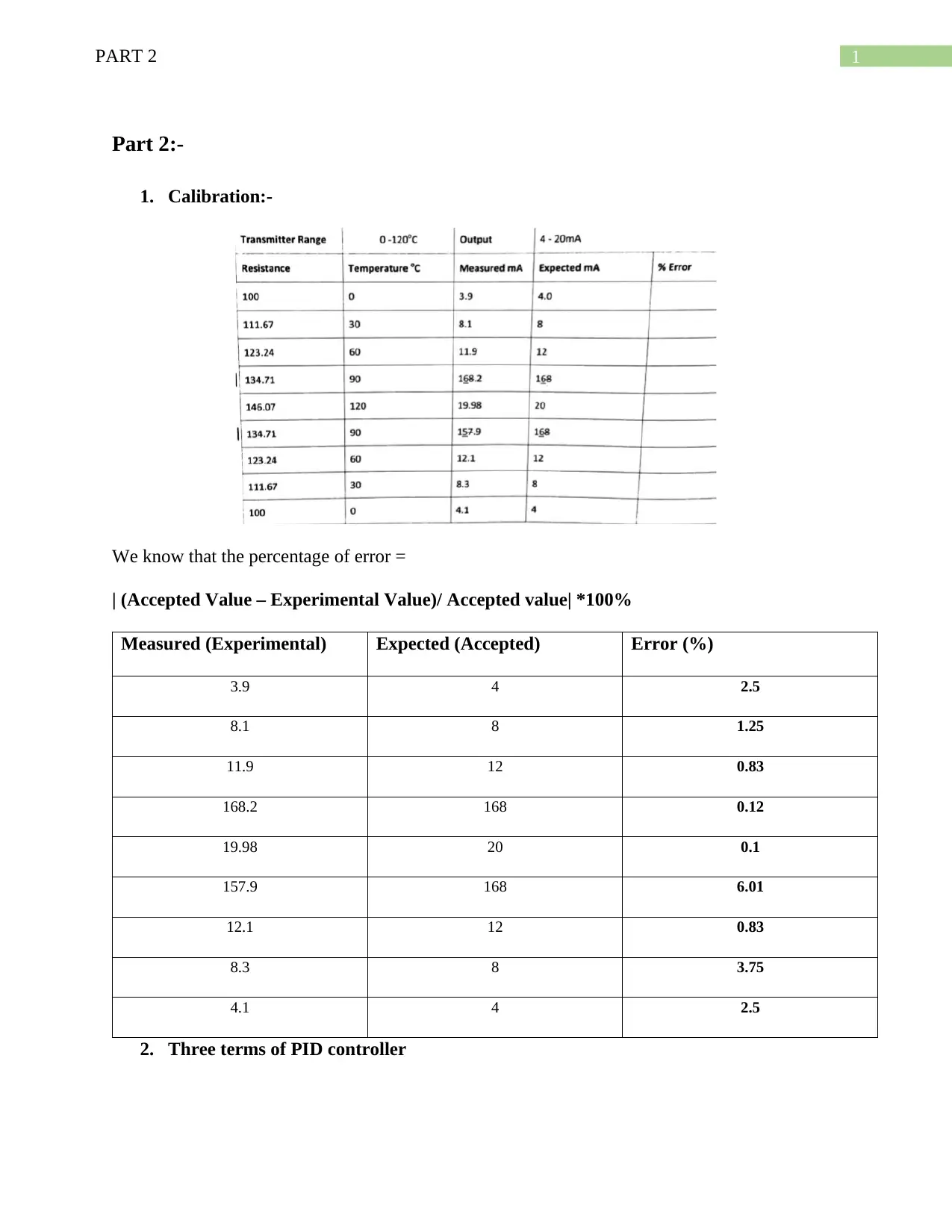
1. Calibration:-
We know that the percentage of error =
| (Accepted Value – Experimental Value)/ Accepted value| *100%
Measured (Experimental) Expected (Accepted) Error (%)
3.9 4 2.5
8.1 8 1.25
11.9 12 0.83
168.2 168 0.12
19.98 20 0.1
157.9 168 6.01
12.1 12 0.83
8.3 8 3.75
4.1 4 2.5
2. Three terms of PID controller
2PART 2
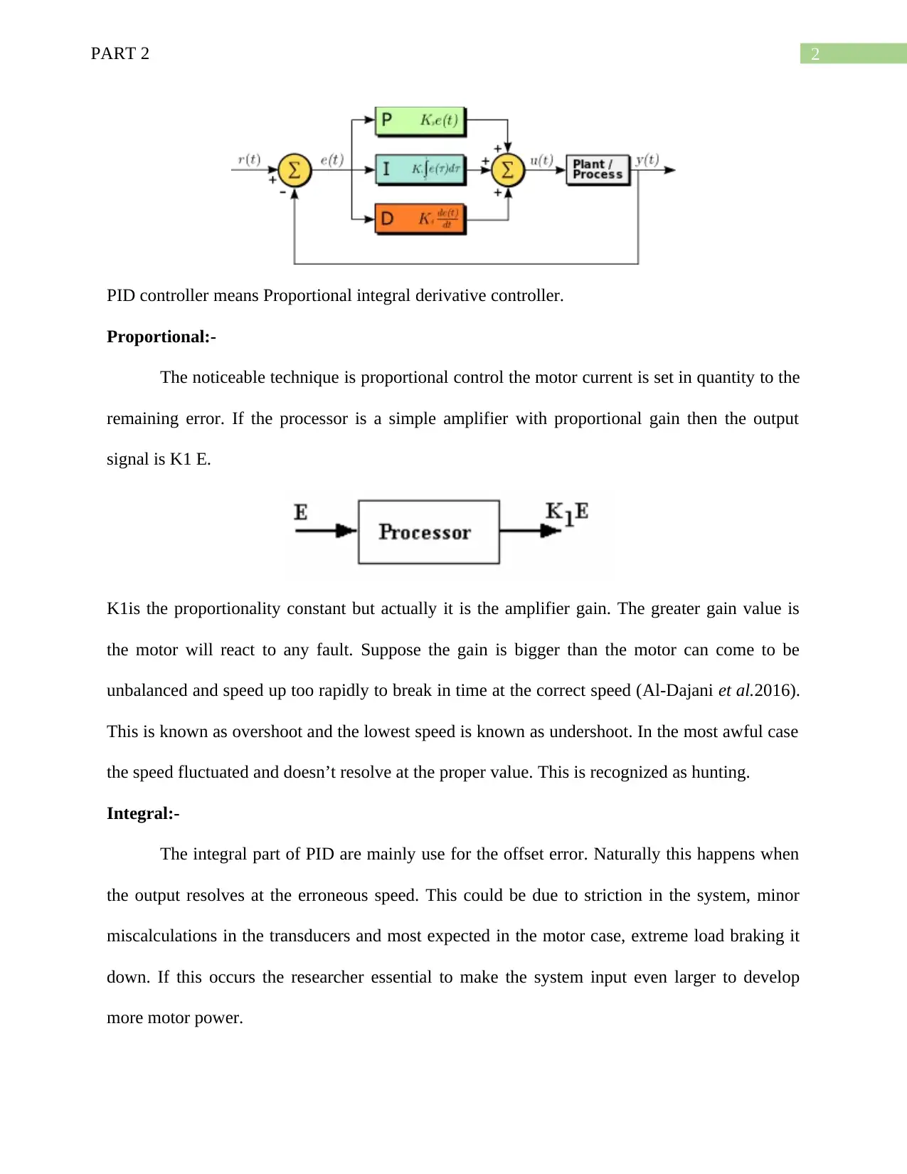
PID controller means Proportional integral derivative controller.
Proportional:-
The noticeable technique is proportional control the motor current is set in quantity to the
remaining error. If the processor is a simple amplifier with proportional gain then the output
signal is K1 E.
K1is the proportionality constant but actually it is the amplifier gain. The greater gain value is
the motor will react to any fault. Suppose the gain is bigger than the motor can come to be
unbalanced and speed up too rapidly to break in time at the correct speed (Al-Dajani et al.2016).
This is known as overshoot and the lowest speed is known as undershoot. In the most awful case
the speed fluctuated and doesn’t resolve at the proper value. This is recognized as hunting.
Integral:-
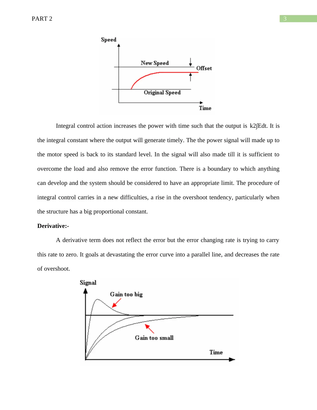
The integral part of PID are mainly use for the offset error. Naturally this happens when
the output resolves at the erroneous speed. This could be due to striction in the system, minor
miscalculations in the transducers and most expected in the motor case, extreme load braking it
down. If this occurs the researcher essential to make the system input even larger to develop
more motor power.
⊘ This is a preview!⊘
Do you want full access?
Subscribe today to unlock all pages.

Trusted by 1+ million students worldwide
3PART 2
Integral control action increases the power with time such that the output is k2∫Edt. It is
the integral constant where the output will generate timely. The the power signal will made up to
the motor speed is back to its standard level. In the signal will also made till it is sufficient to
overcome the load and also remove the error function. There is a boundary to which anything
can develop and the system should be considered to have an appropriate limit. The procedure of
integral control carries in a new difficulties, a rise in the overshoot tendency, particularly when
the structure has a big proportional constant.
Derivative:-
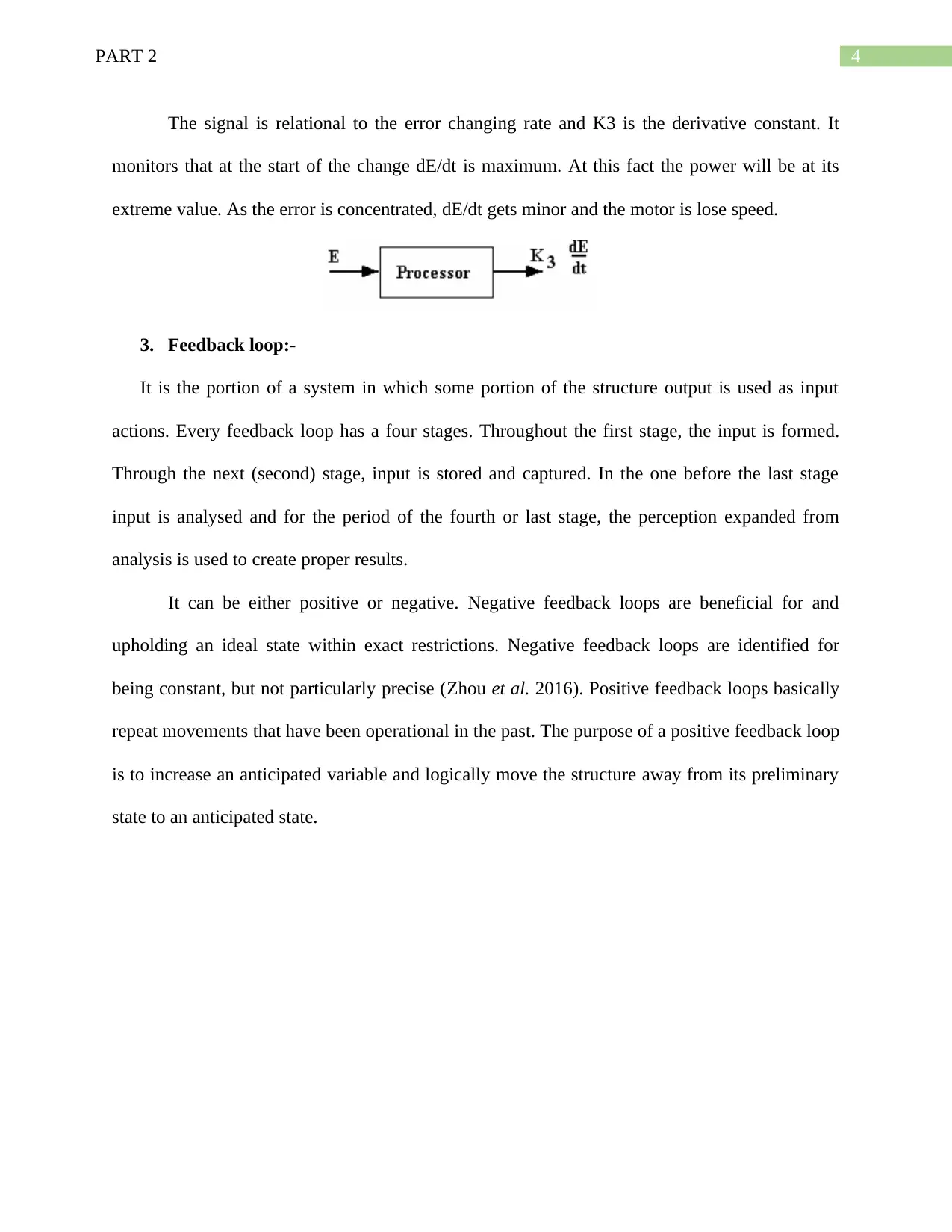
A derivative term does not reflect the error but the error changing rate is trying to carry
this rate to zero. It goals at devastating the error curve into a parallel line, and decreases the rate
of overshoot.
Paraphrase This Document
Need a fresh take? Get an instant paraphrase of this document with our AI Paraphraser
4PART 2
The signal is relational to the error changing rate and K3 is the derivative constant. It
monitors that at the start of the change dE/dt is maximum. At this fact the power will be at its
extreme value. As the error is concentrated, dE/dt gets minor and the motor is lose speed.
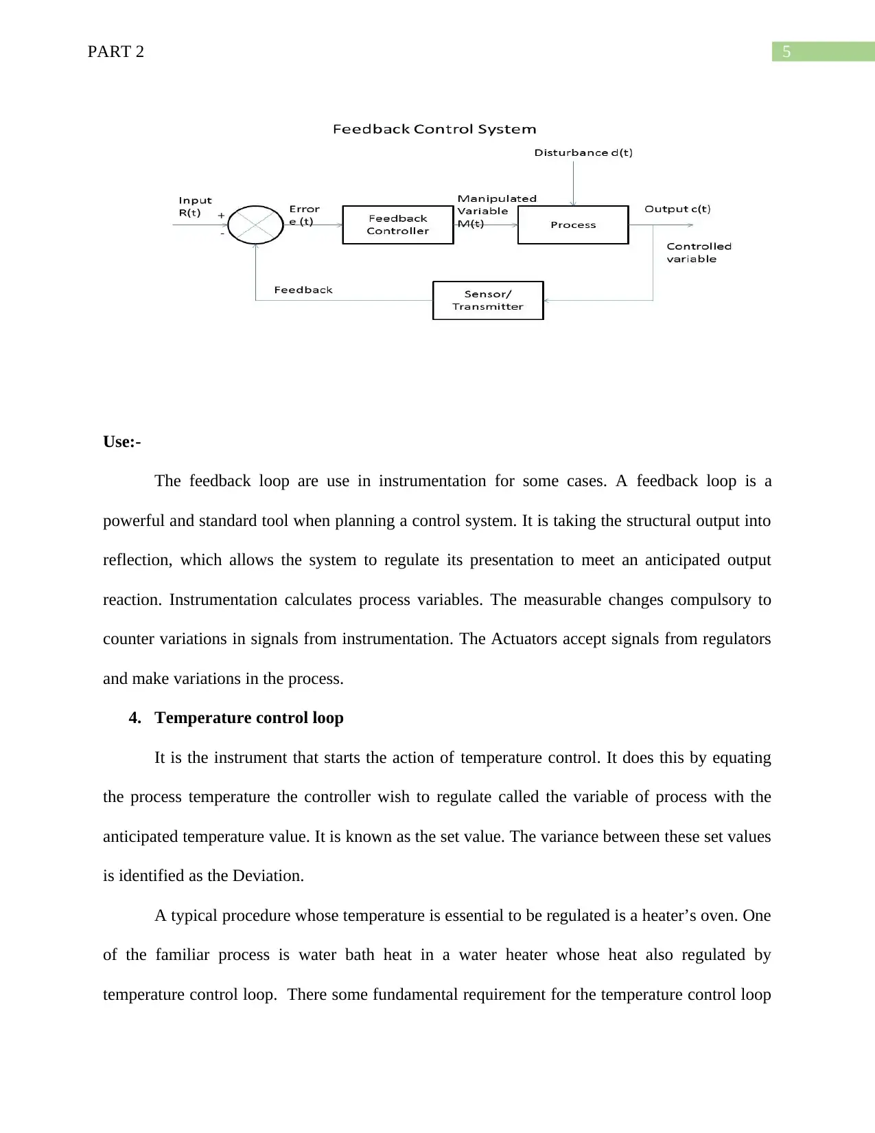
3. Feedback loop:-
It is the portion of a system in which some portion of the structure output is used as input
actions. Every feedback loop has a four stages. Throughout the first stage, the input is formed.
Through the next (second) stage, input is stored and captured. In the one before the last stage
input is analysed and for the period of the fourth or last stage, the perception expanded from
analysis is used to create proper results.
It can be either positive or negative. Negative feedback loops are beneficial for and
upholding an ideal state within exact restrictions. Negative feedback loops are identified for
being constant, but not particularly precise (Zhou et al. 2016). Positive feedback loops basically
repeat movements that have been operational in the past. The purpose of a positive feedback loop
is to increase an anticipated variable and logically move the structure away from its preliminary
state to an anticipated state.
5PART 2
Use:-
The feedback loop are use in instrumentation for some cases. A feedback loop is a
powerful and standard tool when planning a control system. It is taking the structural output into
reflection, which allows the system to regulate its presentation to meet an anticipated output
reaction. Instrumentation calculates process variables. The measurable changes compulsory to
counter variations in signals from instrumentation. The Actuators accept signals from regulators
and make variations in the process.
4. Temperature control loop
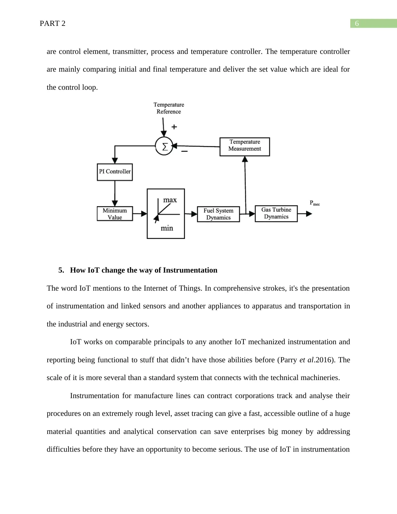
It is the instrument that starts the action of temperature control. It does this by equating
the process temperature the controller wish to regulate called the variable of process with the
anticipated temperature value. It is known as the set value. The variance between these set values
is identified as the Deviation.
A typical procedure whose temperature is essential to be regulated is a heater’s oven. One
of the familiar process is water bath heat in a water heater whose heat also regulated by
temperature control loop. There some fundamental requirement for the temperature control loop
⊘ This is a preview!⊘
Do you want full access?
Subscribe today to unlock all pages.

Trusted by 1+ million students worldwide
6PART 2
are control element, transmitter, process and temperature controller. The temperature controller
are mainly comparing initial and final temperature and deliver the set value which are ideal for
the control loop.
5. How IoT change the way of Instrumentation
The word IoT mentions to the Internet of Things. In comprehensive strokes, it's the presentation
of instrumentation and linked sensors and another appliances to apparatus and transportation in
the industrial and energy sectors.
IoT works on comparable principals to any another IoT mechanized instrumentation and
reporting being functional to stuff that didn’t have those abilities before (Parry et al.2016). The
scale of it is more several than a standard system that connects with the technical machineries.
Instrumentation for manufacture lines can contract corporations track and analyse their
procedures on an extremely rough level, asset tracing can give a fast, accessible outline of a huge
material quantities and analytical conservation can save enterprises big money by addressing
difficulties before they have an opportunity to become serious. The use of IoT in instrumentation
Paraphrase This Document
Need a fresh take? Get an instant paraphrase of this document with our AI Paraphraser
7PART 2
are developing in a daily basis. Several smart city application, smart home, smart business,
logistics, farming which are developed for the IoT implementation.
6. Why we employ offset to our standard signals and how it can be of benefit
The usual current signal in use currently for manufacturing or conservational sensors, classically
wired to PLC is 4-20mA, with 4mA demonstrating zero percent of the restrained value and
20mA signifying 100 percent of the calculated value. Present signals are frequently used in
sensors since the current reaction is generally more linear than the voltage reaction. The current
signals also usually deliver a low sensors impedance, with the advantage of improve noise
immunity.
The voltages supply used with 4-20 mA in DC which depending on the application.
Conversely, the power supply desires to be at a 10% upper potential than the voltage drop of the
initial requirements like receiver, transmitter. The fundamental requirements of a 4-20mA loop
include a transmitter, a receiver, a power source, a sensor, a loop, a receiver.
Benefit:-
One significant benefit of 4-20mA current loops is security. Suppose the 20v power
supply cannot create a danger from the time when the current is not maximum. The current loop
(4-20mA) is essentially safe for harmful areas that may contain hazardous levels of vapour and
dust because the low power depletion does not root combustion if standard functioning or fault
situations are in play.
The advantage are that these current loop is the leading industry standard, is well for
extensive distances, is the modest to link and construct, uses fewer wiring than parallel systems,
and is most easier to troubleshoot for mutual difficulties like destroyed wires.
7. Errors of Instruments?
8PART 2
The dimension of a quantity is based on some universal standards which are entirely correct
related with others. Usually, any quantity measurement is done by relating it with derivative
values with which they are not totally correct.
It is very significant for the worker to take suitable care of the research while acting on
manufacturing instruments so that the error in quantity can be decreased. The few mistakes are
perpetual in nature due to the indefinite explanations, few will be accidental in nature, and
another will be due to gross blunder on the experimenter part.
Measurement Error:-
It is the outcome of the difference of a calculation of the actual value. Generally,
Measurement error involves of an arbitrary error and methodical error. The two type of
Measurement Errors are random errors and systematic error. The best instance of the
measurement error is, if the measurement scale are loaded with 1kg normal weight and the
reading is 10009 grams, then The measurement error is = (1009 grams-1000 grams) = 9 grams.
The Systematic errors that happen due to mistake in the evaluating device are identified
as systematic errors. Generally they are named as Zero Error or else negative error and positive
error. These mistakes can be separate by modifying the measurement device. On the other hand
Random errors are initiated by the unexpected variation in experimental situations and noise and
exhaustion in the operational persons.
Observational Error:-
It is the modification between a calculated quantity value and its exact value. It is an error
is not a fault. Inconsistency is an essential part of the results of calculations and of the
measurement procedure. These categories of errors occurs due to wrong explanations or reading
in the instruments predominantly in case of energy meter reading. The erroneous explanations
⊘ This is a preview!⊘
Do you want full access?
Subscribe today to unlock all pages.

Trusted by 1+ million students worldwide
9PART 2
may be due to PARALLAX. In order to decrease the PARALLAX error extremely correct
meters are needed which are delivered with mirror scales.
Instrumental error:-
It happen due to incorrect structure of the calculating instruments. These mistakes may
happen due to friction or hysteresis. These categories of errors contain loading effect and
mismanagement of the instruments (Halverson et al. 2016). In order to decrease the gross
mistakes in measurement, different improvement factors must be useful and in the extreme
situation instrument must be recalibrated cautiously.
It is mentions to the error of a calculating instrument, or the variance between the authentic value
and the value specified by the instrument. There can be faults of several types, and the general
fault is the quantity of the specific errors.
Theoretical error:-
These type of error are produced by explanation of the model system. Suppose a concept states
that the system temperature which adjoining will not alteration the readings taken when it
essentially does, then this cause will instigate a source of error in measurement.
8. A thermocouple with range of 0-1100 degree Celsius is connected to a transmitter
that outputs 4-20mA. It is found to have a span error of 0.5%
The thermocouple temperature range is 0 degree Celsius to 1100 degree Celsius.
This is mainly connected to the transmitter where output is the 4-20mA.
Error span is 0.5%.
The error span is mainly connected to the concerned error. Because the error which can be
identified through the temperature range which fluctuated and diversified with another. The ratio
Paraphrase This Document
Need a fresh take? Get an instant paraphrase of this document with our AI Paraphraser
10PART 2
which must be selected through the conventional point that are creating specific variance of
error. So it is easily state that these error of thermocouple are concerned with the span of error.
9. Direct and Indirect Measurement
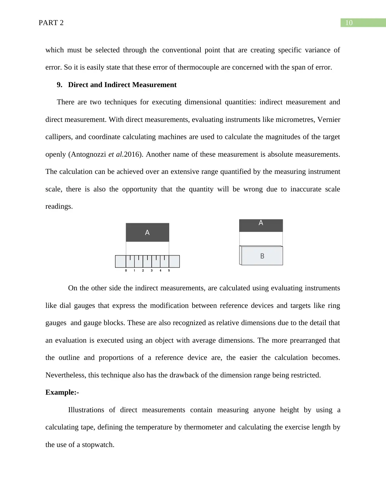
There are two techniques for executing dimensional quantities: indirect measurement and
direct measurement. With direct measurements, evaluating instruments like micrometres, Vernier
callipers, and coordinate calculating machines are used to calculate the magnitudes of the target
openly (Antognozzi et al.2016). Another name of these measurement is absolute measurements.
The calculation can be achieved over an extensive range quantified by the measuring instrument
scale, there is also the opportunity that the quantity will be wrong due to inaccurate scale
readings.
On the other side the indirect measurements, are calculated using evaluating instruments
like dial gauges that express the modification between reference devices and targets like ring
gauges and gauge blocks. These are also recognized as relative dimensions due to the detail that
an evaluation is executed using an object with average dimensions. The more prearranged that
the outline and proportions of a reference device are, the easier the calculation becomes.
Nevertheless, this technique also has the drawback of the dimension range being restricted.
Example:-
Illustrations of direct measurements contain measuring anyone height by using a
calculating tape, defining the temperature by thermometer and calculating the exercise length by
the use of a stopwatch.
11PART 2
Consider we wanted to shape a bridge through a small canal where the plot on one side of
the canal is higher than the plot on the other. Let the river is 30 ft. wide where want to made the
bridge, and also know that the upper side of the canal is 5 ft. from the seawater. Indirect
measurement usually includes properties affecting to the Pythagorean Theorem, magnitudes,
similar polygons, and others.
10. Uses of Current pressure Converter
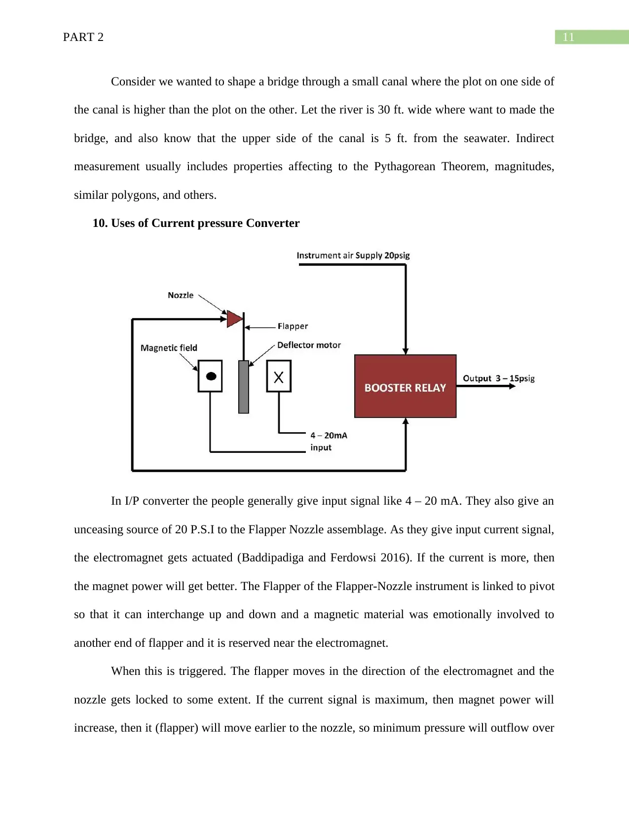
In I/P converter the people generally give input signal like 4 – 20 mA. They also give an
unceasing source of 20 P.S.I to the Flapper Nozzle assemblage. As they give input current signal,
the electromagnet gets actuated (Baddipadiga and Ferdowsi 2016). If the current is more, then
the magnet power will get better. The Flapper of the Flapper-Nozzle instrument is linked to pivot
so that it can interchange up and down and a magnetic material was emotionally involved to
another end of flapper and it is reserved near the electromagnet.
When this is triggered. The flapper moves in the direction of the electromagnet and the
nozzle gets locked to some extent. If the current signal is maximum, then magnet power will
increase, then it (flapper) will move earlier to the nozzle, so minimum pressure will outflow over
⊘ This is a preview!⊘
Do you want full access?
Subscribe today to unlock all pages.

Trusted by 1+ million students worldwide
1 out of 16
Related Documents
Your All-in-One AI-Powered Toolkit for Academic Success.
+13062052269
info@desklib.com
Available 24*7 on WhatsApp / Email
![[object Object]](/_next/static/media/star-bottom.7253800d.svg)
Unlock your academic potential
Copyright © 2020–2025 A2Z Services. All Rights Reserved. Developed and managed by ZUCOL.


