Record New Tour
VerifiedAdded on 2022/11/25
|12
|1851
|482
AI Summary
This document provides an overview of the class diagram, communication diagram, and sequence diagram in the context of recording a new tour. It explains their descriptions, their use in system analysis, and evaluates the use of Enterprise Architect as a case tool for developing the World-Wide Tour system.
Contribute Materials
Your contribution can guide someone’s learning journey. Share your
documents today.
Running head: RECORD NEW TOUR
RECORD NEW TOUR
Name of the student:
Name of the university:
Author Note:
RECORD NEW TOUR
Name of the student:
Name of the university:
Author Note:
Secure Best Marks with AI Grader
Need help grading? Try our AI Grader for instant feedback on your assignments.
1RECORD NEW TOUR
Table of Contents
Class Diagram............................................................................................................................2
Description of class diagram..................................................................................................2
Description of diagram...........................................................................................................2
Communication diagram............................................................................................................3
Description of communication diagram.................................................................................3
Description of the diagram.....................................................................................................3
Sequence diagram......................................................................................................................4
Description of sequence diagram...........................................................................................4
Description of the diagram.....................................................................................................4
Evaluation..................................................................................................................................5
2RECORD NEW TOUR
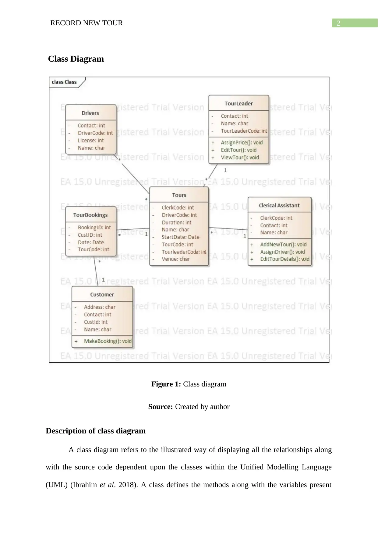
Class Diagram
Figure 1: Class diagram
Source: Created by author
Description of class diagram
A class diagram refers to the illustrated way of displaying all the relationships along
with the source code dependent upon the classes within the Unified Modelling Language
(UML) (Ibrahim et al. 2018). A class defines the methods along with the variables present
3RECORD NEW TOUR
within an object, which specifies the entity related to a program or the individual code
making proper representations of the entire entity.
Class diagram in the processes of system analysis is not only utilized for the method
of visualizing, describing as well as documenting but also for the construction of the
executable code belonging to the application of the respective software.
Description of diagram
In the above class diagram, the customers is the one to initiate the entire process by
filling in all the details such as the like of address, contact details, customer ID as well as
name belonging to the same. By filling in all the details, the customer makes bookings
regarding its tour. Each individual tour will have all the details that is required by the
customer to book according to their preferences. The details related to the tour that is visible
to the customers are,
clerk code
Driver code
Duration of the tour.
Start date of the tour.
Code for the tour.
Code for the leader of the tour.
Details of the venue.
After the booking is done, the clerk will attend the customers and help them with the
required amount of assistance. The clerks too have details such as the code, contact as well as
name of the clerk. After the tourists get attended by the clerk, the tour leader is appointed to
the customer for the rest of the tour. In addition to this, the entire tour is assigned to a driver
Secure Best Marks with AI Grader
Need help grading? Try our AI Grader for instant feedback on your assignments.
4RECORD NEW TOUR
who is in charge of the entire travelling having the inclusion of contact details, code, license
as well as name of the driver.
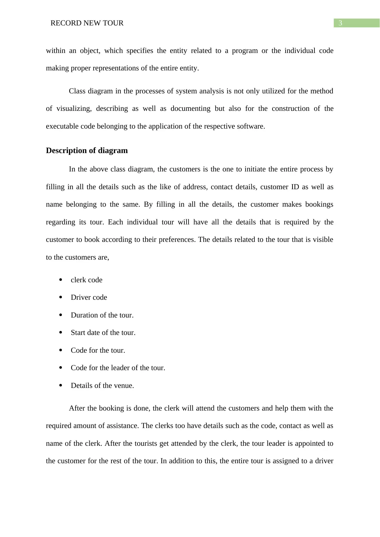
Communication diagram
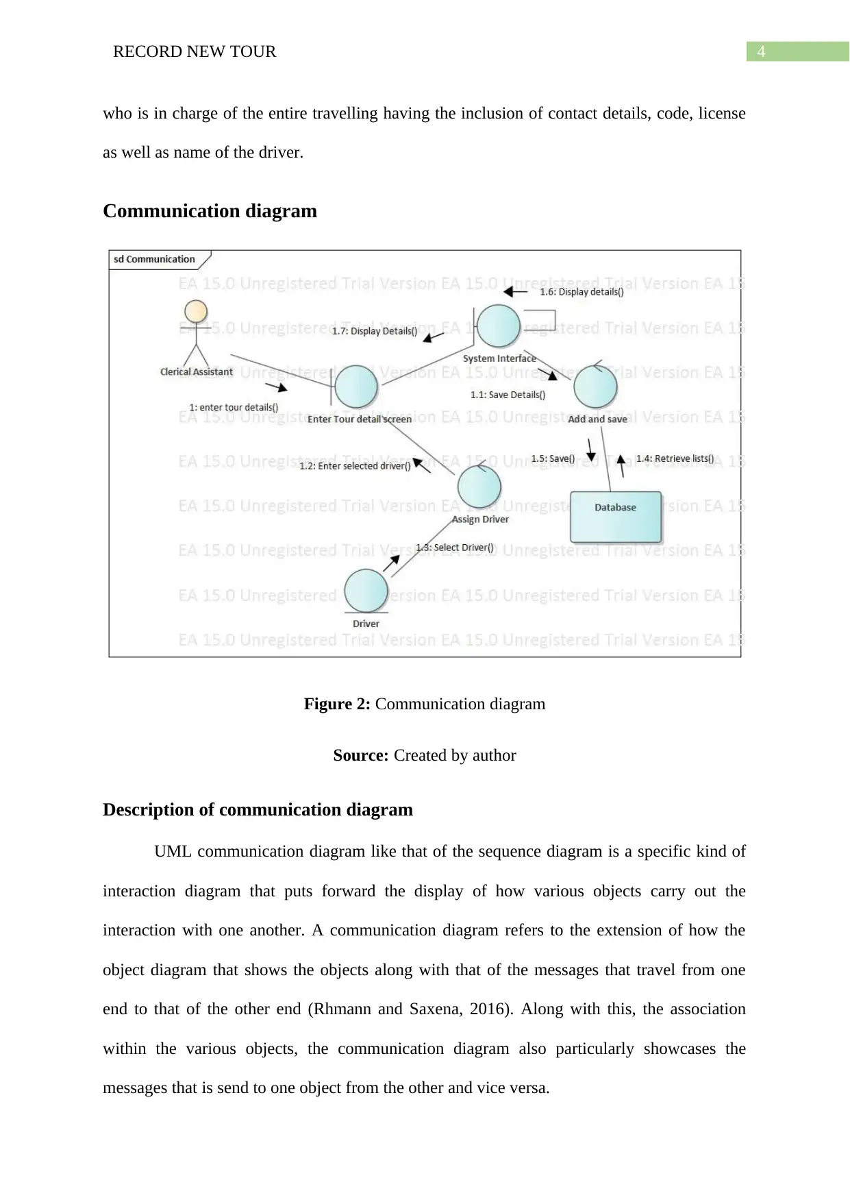
Figure 2: Communication diagram
Source: Created by author
Description of communication diagram
UML communication diagram like that of the sequence diagram is a specific kind of
interaction diagram that puts forward the display of how various objects carry out the
interaction with one another. A communication diagram refers to the extension of how the
object diagram that shows the objects along with that of the messages that travel from one
end to that of the other end (Rhmann and Saxena, 2016). Along with this, the association
within the various objects, the communication diagram also particularly showcases the
messages that is send to one object from the other and vice versa.
who is in charge of the entire travelling having the inclusion of contact details, code, license
as well as name of the driver.
Communication diagram
Figure 2: Communication diagram
Source: Created by author
Description of communication diagram
UML communication diagram like that of the sequence diagram is a specific kind of
interaction diagram that puts forward the display of how various objects carry out the
interaction with one another. A communication diagram refers to the extension of how the
object diagram that shows the objects along with that of the messages that travel from one
end to that of the other end (Rhmann and Saxena, 2016). Along with this, the association
within the various objects, the communication diagram also particularly showcases the
messages that is send to one object from the other and vice versa.
5RECORD NEW TOUR
In the process of system analysis, the communication diagram puts forward the entire
line of communication that is carried out within different objects belonging to a specific
system (Ferenc, Polasek and Vincur 2017). In addition to this, the messages are typically
highlighted as well.
Description of the diagram
The communication diagram consists of a single actor, which is the clerical assistant
who has the primary responsibility of providing each of the customers with the necessary
assistance that they need during the entire span of the tour.
The assistant enters the screen, which consists of all the details related to the tour
undertaken by the customer. Depending on the tour selected by the customer, the driver is
assigned to carry the customer to each of the places, which is a part of the tour. The tour
screen shows all the details belonging to the driver to the customer as well as the clerk for
required information of the entire tour and for emergencies.
6RECORD NEW TOUR
Sequence diagram
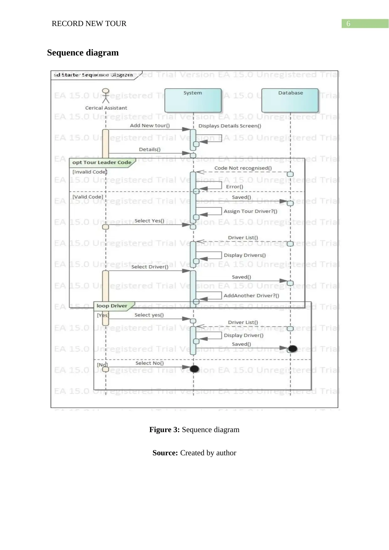
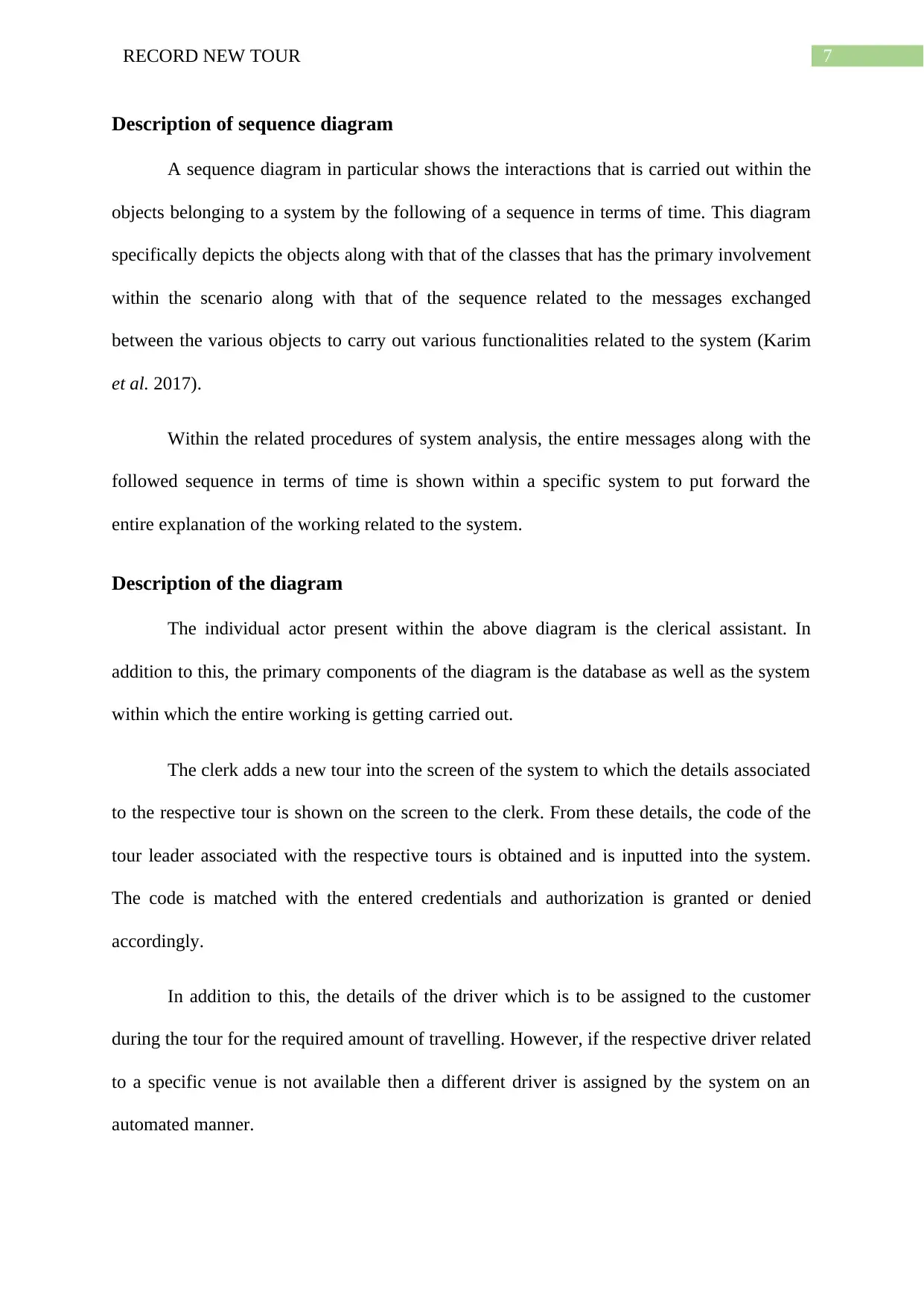
Figure 3: Sequence diagram
Source: Created by author
Sequence diagram
Figure 3: Sequence diagram
Source: Created by author
Paraphrase This Document
Need a fresh take? Get an instant paraphrase of this document with our AI Paraphraser
7RECORD NEW TOUR
Description of sequence diagram
A sequence diagram in particular shows the interactions that is carried out within the
objects belonging to a system by the following of a sequence in terms of time. This diagram
specifically depicts the objects along with that of the classes that has the primary involvement
within the scenario along with that of the sequence related to the messages exchanged
between the various objects to carry out various functionalities related to the system (Karim
et al. 2017).
Within the related procedures of system analysis, the entire messages along with the
followed sequence in terms of time is shown within a specific system to put forward the
entire explanation of the working related to the system.
Description of the diagram
The individual actor present within the above diagram is the clerical assistant. In
addition to this, the primary components of the diagram is the database as well as the system
within which the entire working is getting carried out.
The clerk adds a new tour into the screen of the system to which the details associated
to the respective tour is shown on the screen to the clerk. From these details, the code of the
tour leader associated with the respective tours is obtained and is inputted into the system.
The code is matched with the entered credentials and authorization is granted or denied
accordingly.
In addition to this, the details of the driver which is to be assigned to the customer
during the tour for the required amount of travelling. However, if the respective driver related
to a specific venue is not available then a different driver is assigned by the system on an
automated manner.
8RECORD NEW TOUR
Evaluation
A case tool refers to the application software that is specifically used for the purpose of
automating any respective activity that has a complete association with that of any software
development procedure having the primary inclusion of web development, e-commerce
development, development of mobile application as well as other methods of system
development. For the development of such procedures, a case tool is used (Van Den Berg and
Van Vliet, 2016).
Enterprise Architect is one of such case tools that has been specifically utilized for the
development of the World-Wide Tour system (Lagerström et al. 2014). Firstly, the class
diagram has been developed with the help of enterprise architecture wherein the entire
description of all the actors belonging to the system has been done along with all the personal
details belonging to the same has been described with the help of the diagram.
Following this, the communication diagram has been developed with the help of the
same case tool, which particularly shows the entire communication procedure of the system
dependent upon which the world tour system is functioning (Besker, Olsson and Pessi, 2015).
The communication is specifically the interaction that all the entities as well as the objects of
the system carries out with the help of the tools present within this system. The
communication is tracked with the help of the enterprise architect.
In addition to this, the sequence diagram that has been developed with the help of
enterprise architect shows the interaction that is carried out among all the objects belonging
to this system. In addition to this, the interaction is completely based upon the timeframe that
is dependent upon a proper functioning of the system. The sequence diagram specifically
shows the messages that are sent from object to that of the other existing objects belonging to

9RECORD NEW TOUR
the system for a better working of the same (Plataniotis et al. 2015). The messages are sent to
the objects from individual entities or objects having a complete dependency upon time.
Hence, Enterprise Architect has provisioned with a greater helping hands towards the
proper utilization of all the resources needed for a successful development of a working
system and to put forward the required amount of perfection that is needed to satisfy the
customer with a tour system in an easy way.
Secure Best Marks with AI Grader
Need help grading? Try our AI Grader for instant feedback on your assignments.
10RECORD NEW TOUR
References
Besker, T., Olsson, R. and Pessi, K., 2015, September. The Enterprise Architect profession:
An empirical study. In ECIME2015-9th Eur. Conf. IS Manag. Eval. ECIME 2015 (pp. 21-
22).
Ferenc, M., Polasek, I. and Vincur, J., 2017, September. Collaborative Modeling and
Visualization of Software Systems Using Multidimensional UML. In 2017 IEEE Working
Conference on Software Visualization (VISSOFT) (pp. 99-103). IEEE.
Ibrahim, R., Aman, H., Nayak, R. and Jamel, S., 2018. Consistency Check between XML
Schema and Class Diagram for Document Versioning. International Journal on Advanced
Science, Engineering and Information Technology, 8(6), pp.2590-2597.
Karim, S., Liawatimena, S., Trisetyarso, A., Abbas, B.S. and Suparta, W., 2017, November.
Automating functional and structural software size measurement based on XML structure of
UML sequence diagram. In 2017 IEEE International Conference on Cybernetics and
Computational Intelligence (CyberneticsCom) (pp. 24-28). IEEE.
Lagerström, R., Baldwin, C., MacCormack, A. and Aier, S., 2014, January. Visualizing and
measuring enterprise application architecture: an exploratory telecom case. In 2014 47th
Hawaii International Conference on System Sciences (pp. 3847-3856). IEEE.
Plataniotis, G., Ma, Q., Proper, E. and de Kinderen, S., 2015, May. Traceability and modeling
of requirements in enterprise architecture from a design rationale perspective. In 2015 IEEE
9th International Conference on Research Challenges in Information Science (RCIS) (pp.
518-519). IEEE.
Rhmann, W. and Saxena, V., 2016. Generation of test cases from uml sequence diagram
based on extenics theory. British Journal of Mathematics & Computer Science, 16(1).

11RECORD NEW TOUR
Van Den Berg, M. and Van Vliet, H., 2016, September. The decision-making context
influences the role of the enterprise architect. In 2016 IEEE 20th International Enterprise
Distributed Object Computing Workshop (EDOCW) (pp. 1-8). IEEE.
Van Den Berg, M. and Van Vliet, H., 2016, September. The decision-making context
influences the role of the enterprise architect. In 2016 IEEE 20th International Enterprise
Distributed Object Computing Workshop (EDOCW) (pp. 1-8). IEEE.
1 out of 12
Related Documents


Your All-in-One AI-Powered Toolkit for Academic Success.
+13062052269
info@desklib.com
Available 24*7 on WhatsApp / Email
![[object Object]](/_next/static/media/star-bottom.7253800d.svg)
Unlock your academic potential
© 2024 | Zucol Services PVT LTD | All rights reserved.