CIS2002 Semester 3 Assignment 2: Data Modeling, Normalization, and SQL
VerifiedAdded on 2022/08/24
|15
|1780
|11
Homework Assignment
AI Summary
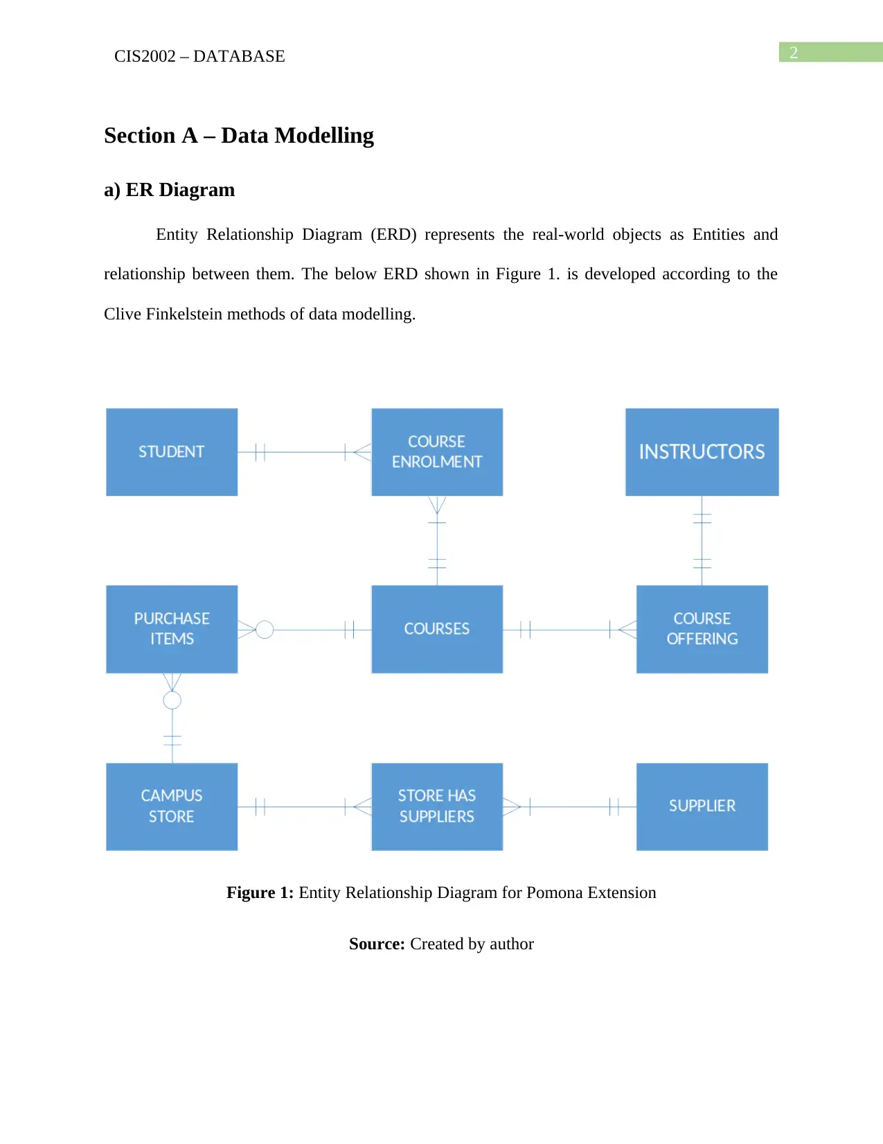
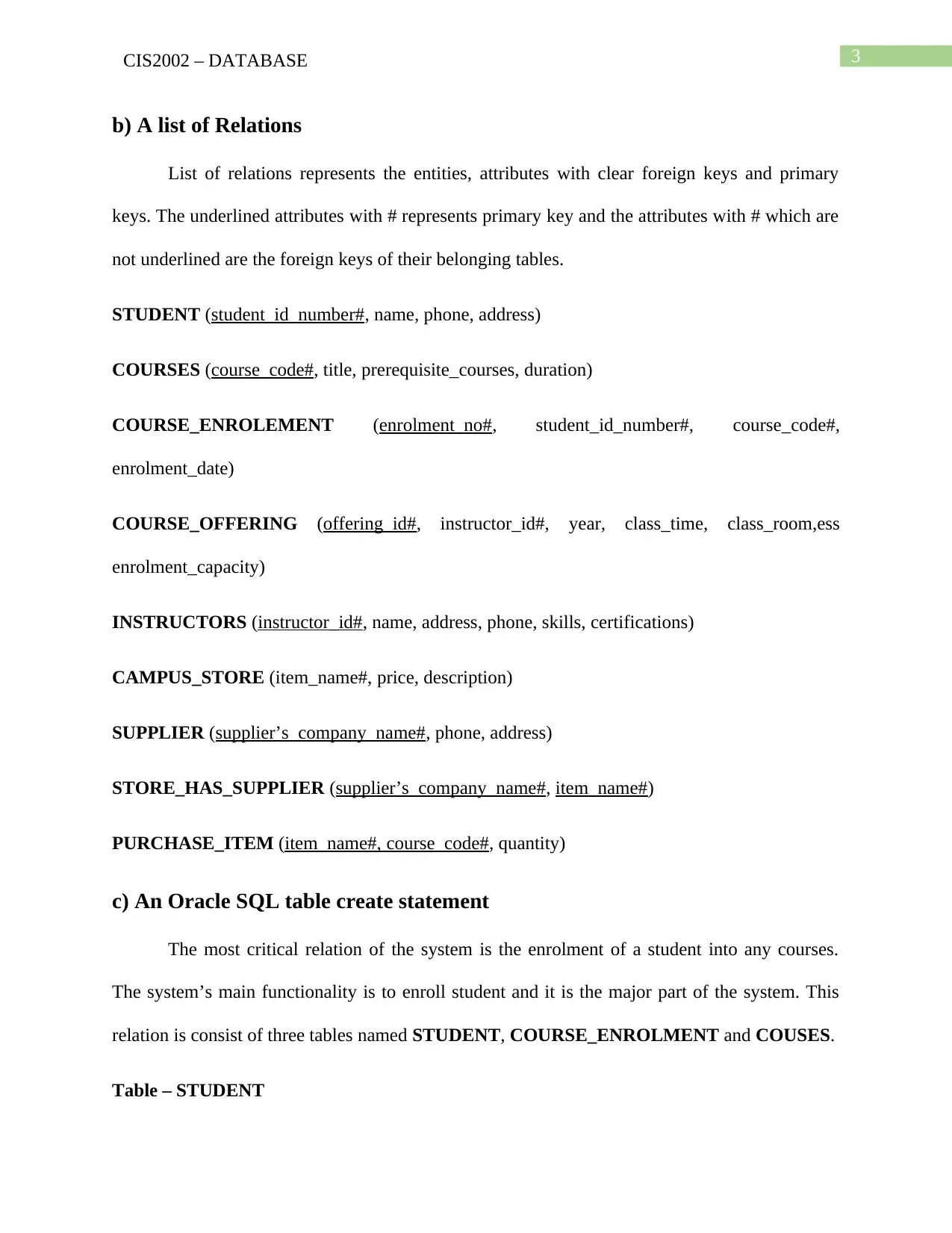
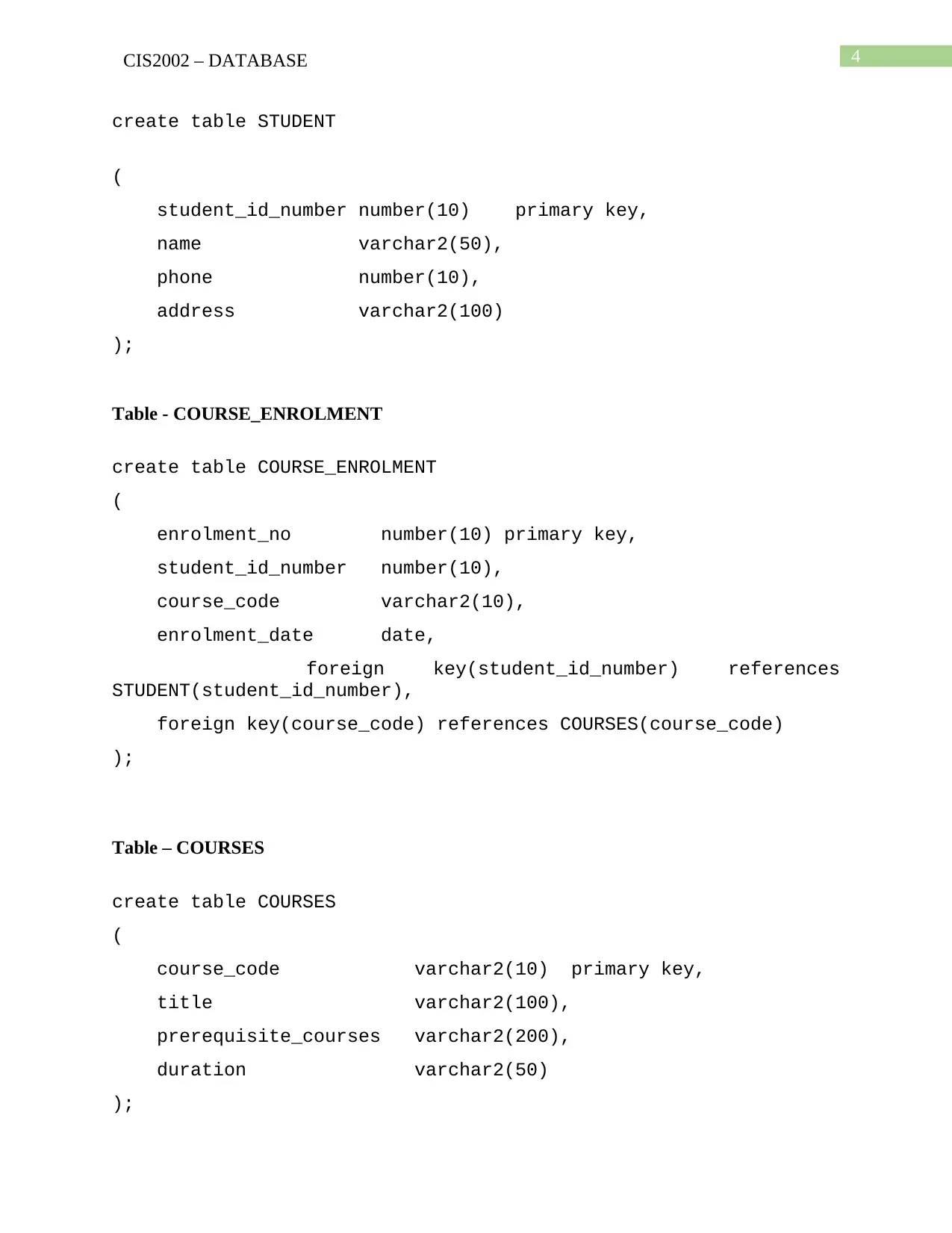
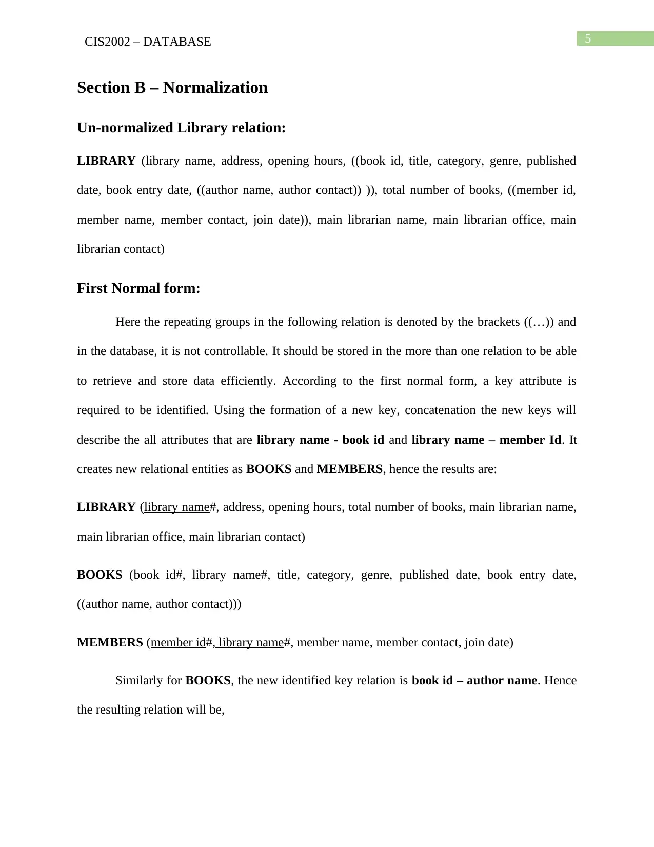
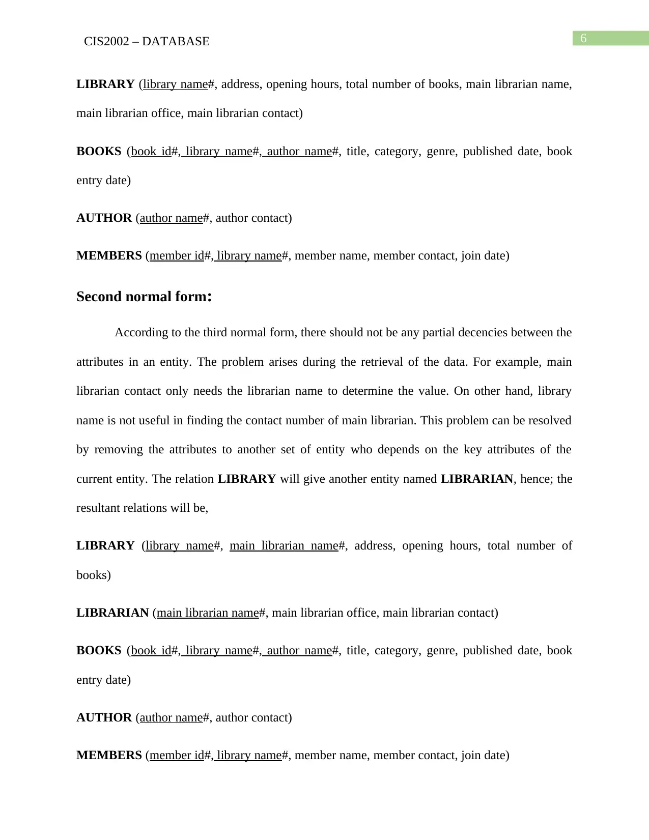
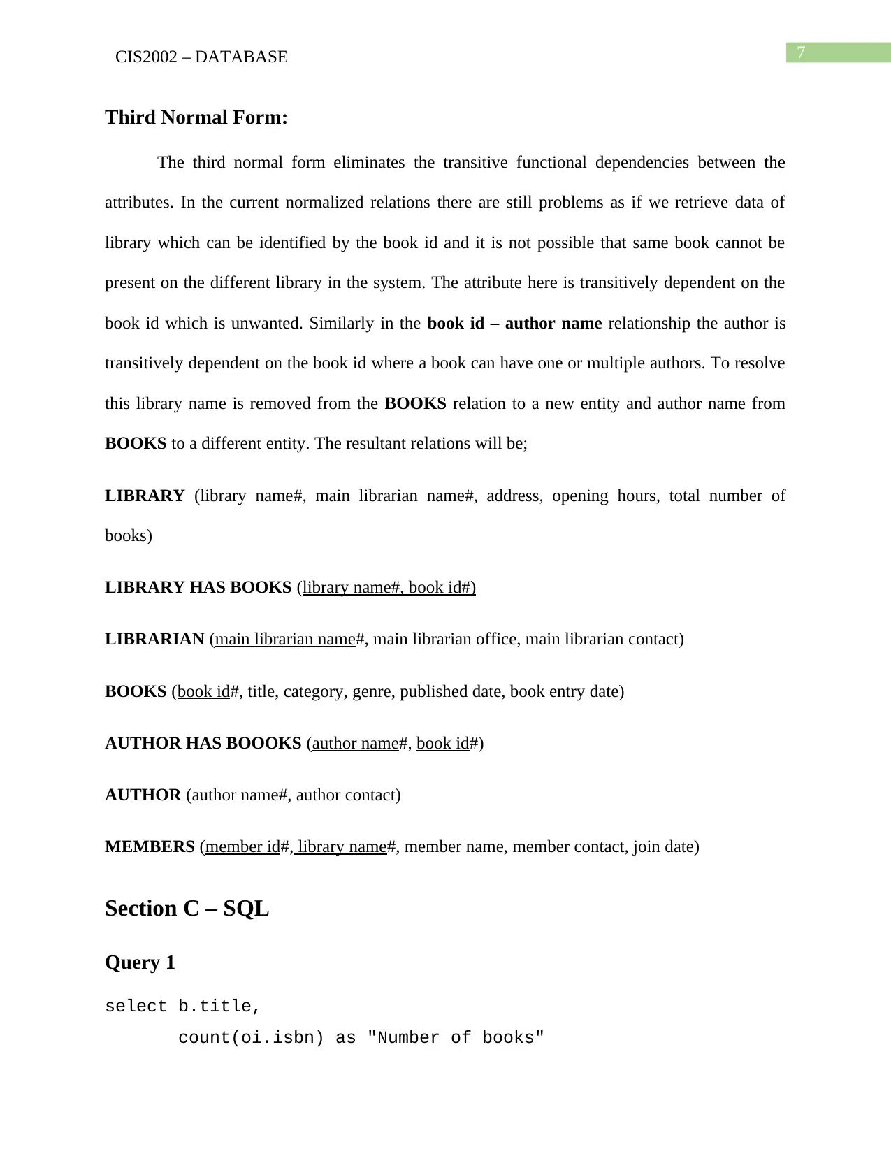
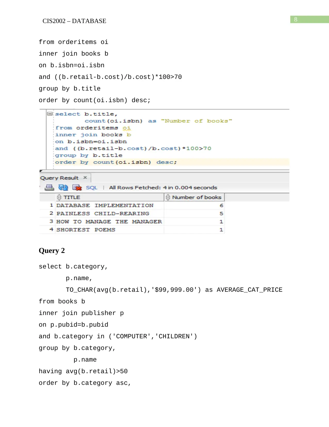
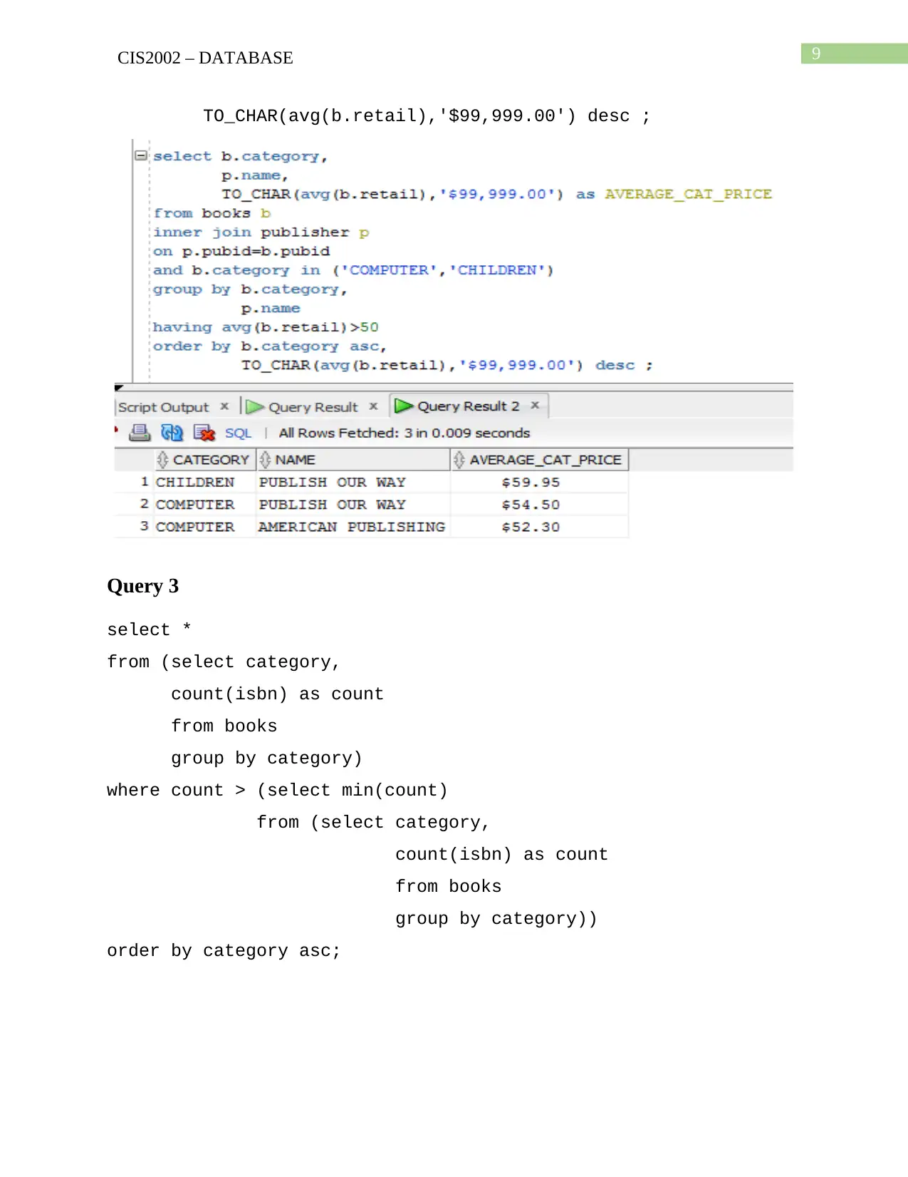
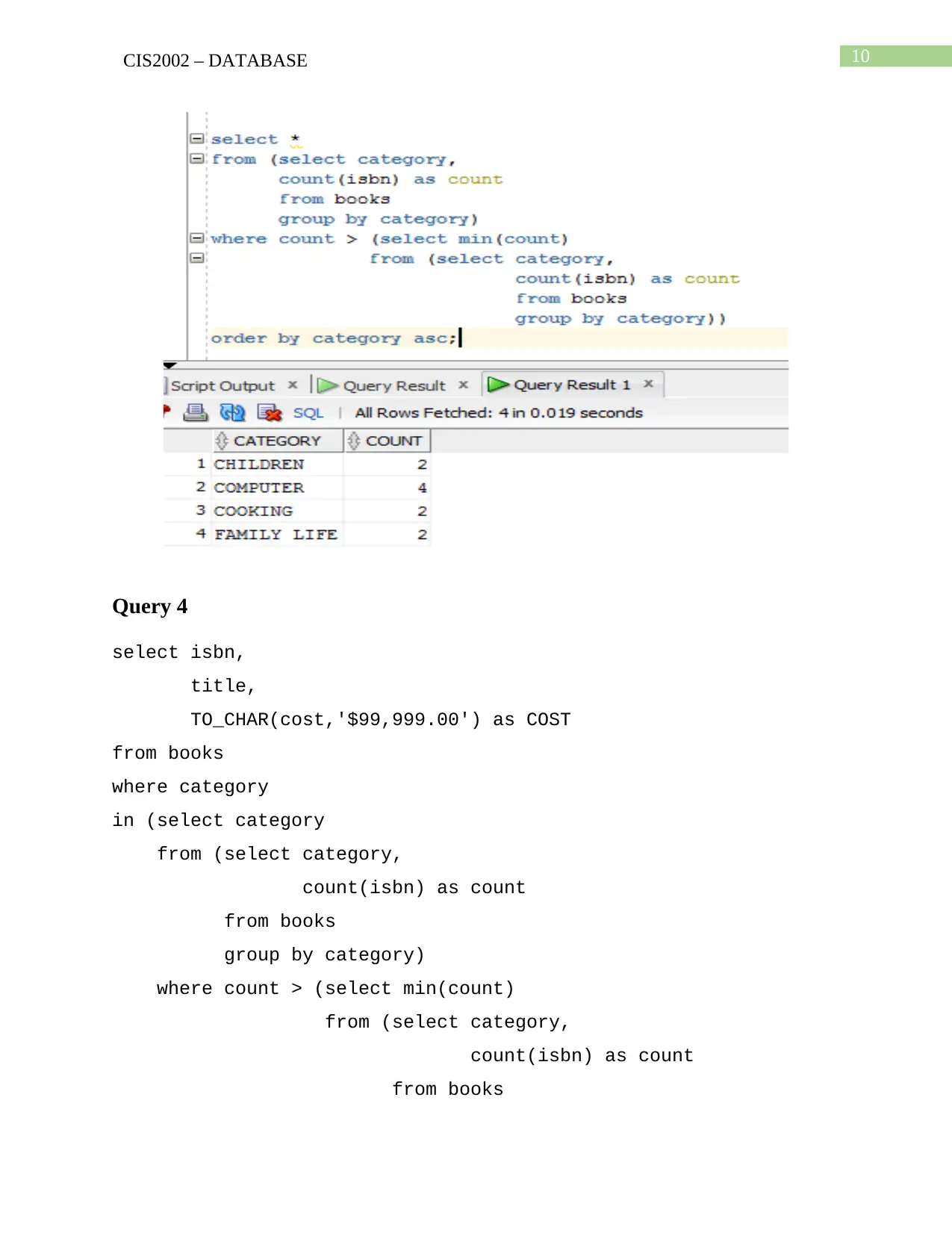
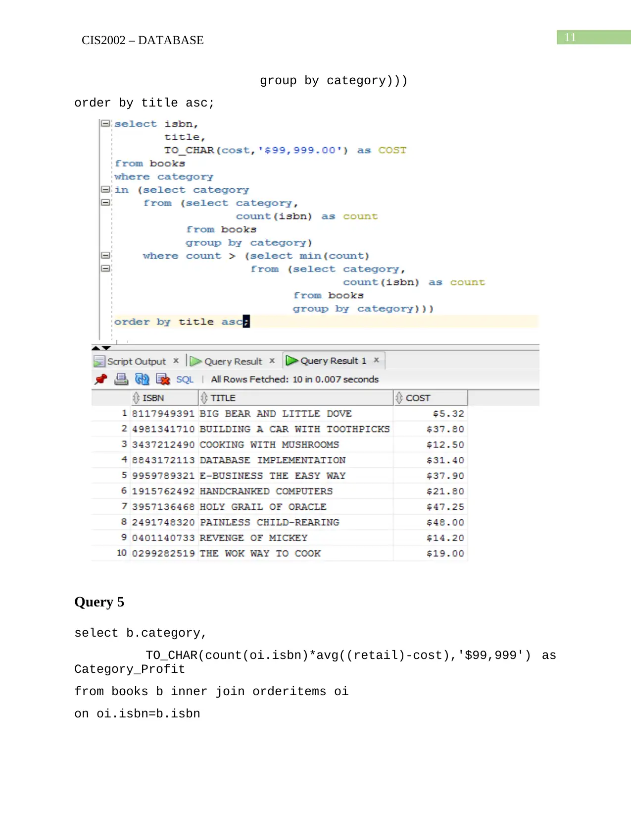
This document presents a comprehensive solution for CIS2002 Assignment 2, focusing on database design and implementation. The assignment begins with Section A, which involves data modeling, including the creation of an Entity Relationship Diagram (ERD) based on Clive Finkelstein's methods, a list of relations, and an Oracle SQL table create statement. Section B delves into database normalization, demonstrating the transformation of an un-normalized library relation through First, Second, and Third Normal Forms. Section C provides SQL queries, including examples for data retrieval and analysis, such as selecting book titles based on profit margins, calculating average category prices, and identifying categories based on book counts and profits. The assignment adheres to USQ's data modeling and normalization methodology and provides a strong foundation for exam preparation. The document concludes with a bibliography of relevant database design resources.
1 out of 15
Related Documents


Your All-in-One AI-Powered Toolkit for Academic Success.
+13062052269
info@desklib.com
Available 24*7 on WhatsApp / Email
![[object Object]](/_next/static/media/star-bottom.7253800d.svg)
Copyright © 2020–2026 A2Z Services. All Rights Reserved. Developed and managed by ZUCOL.