logo

Diagram of rotary screw compressor


Added on  2021-04-17

7 Pages1686 Words117 Views
 | 
 | 
 | 
Running Head: ROTARY SCREW COMPRESSORRotary-screw CompressorNameInstitutional affiliation
Diagram of rotary screw compressor_1

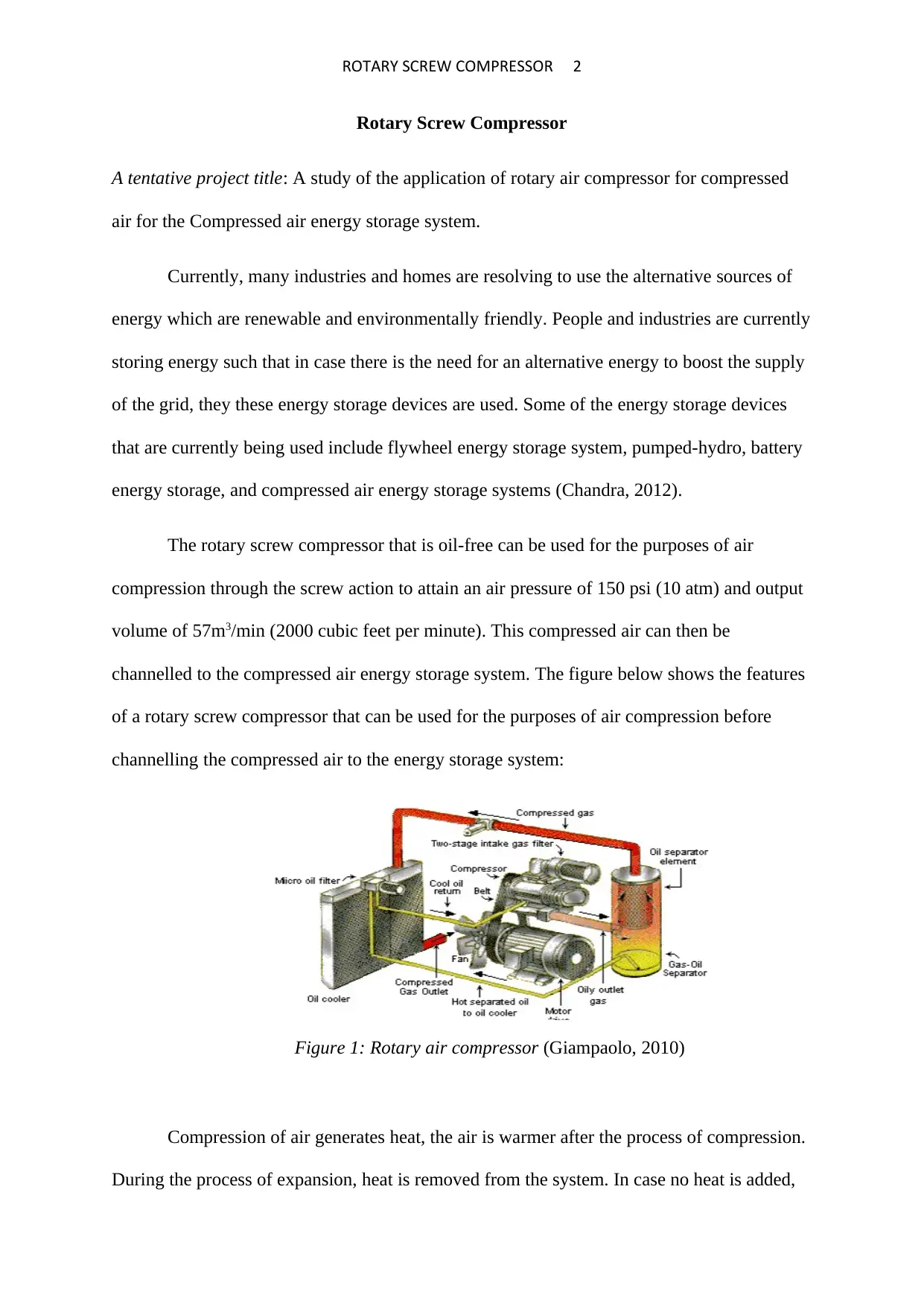
ROTARY SCREW COMPRESSOR 2Rotary Screw CompressorA tentative project title: A study of the application of rotary air compressor for compressed air for the Compressed air energy storage system. Currently, many industries and homes are resolving to use the alternative sources of energy which are renewable and environmentally friendly. People and industries are currentlystoring energy such that in case there is the need for an alternative energy to boost the supply of the grid, they these energy storage devices are used. Some of the energy storage devices that are currently being used include flywheel energy storage system, pumped-hydro, battery energy storage, and compressed air energy storage systems[ CITATION Ram12 \l 2057 ].The rotary screw compressor that is oil-free can be used for the purposes of air compression through the screw action to attain an air pressure of 150 psi (10 atm) and output volume of 57m3/min (2000 cubic feet per minute). This compressed air can then be channelled to the compressed air energy storage system. The figure below shows the features of a rotary screw compressor that can be used for the purposes of air compression before channelling the compressed air to the energy storage system:Figure 1: Rotary air compressor[ CITATION Ton10 \l 2057 ]Compression of air generates heat, the air is warmer after the process of compression. During the process of expansion, heat is removed from the system. In case no heat is added,
Diagram of rotary screw compressor_2

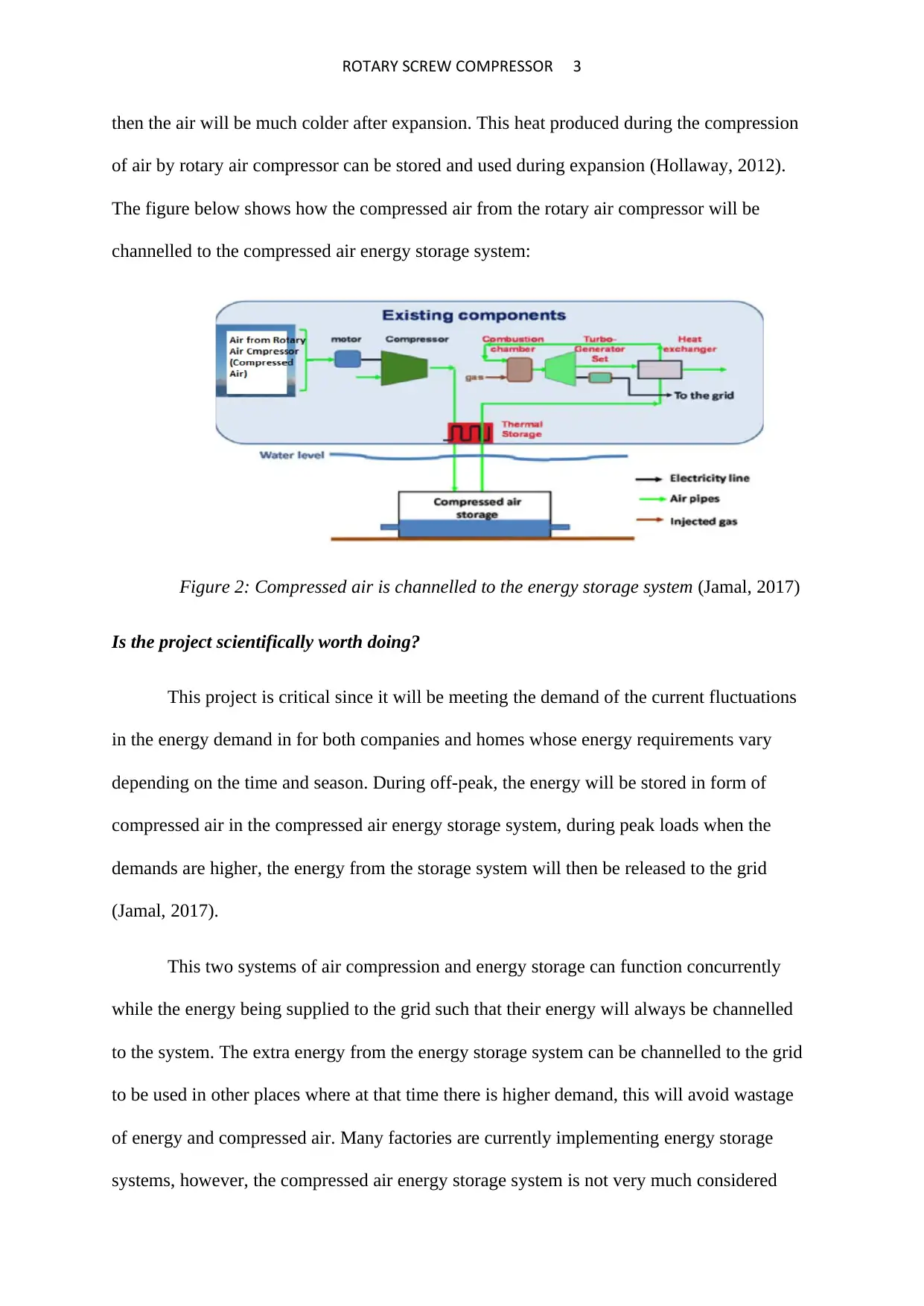
ROTARY SCREW COMPRESSOR 3then the air will be much colder after expansion. This heat produced during the compression of air by rotary air compressor can be stored and used during expansion[ CITATION Mic12 \l 2057 ]. The figure below shows how the compressed air from the rotary air compressor will be channelled to the compressed air energy storage system:Figure 2: Compressed air is channelled to the energy storage system[ CITATION Kar17 \l 2057 ]Is the project scientifically worth doing?This project is critical since it will be meeting the demand of the current fluctuations in the energy demand in for both companies and homes whose energy requirements vary depending on the time and season. During off-peak, the energy will be stored in form of compressed air in the compressed air energy storage system, during peak loads when the demands are higher, the energy from the storage system will then be released to the grid[ CITATION Kar17 \l 2057 ]. This two systems of air compression and energy storage can function concurrently while the energy being supplied to the grid such that their energy will always be channelled to the system. The extra energy from the energy storage system can be channelled to the grid to be used in other places where at that time there is higher demand, this will avoid wastage of energy and compressed air. Many factories are currently implementing energy storage
Diagram of rotary screw compressor_3

End of preview

Want to access all the pages? Upload your documents or become a member.

Related Documents
Design Optimization and Application of Rotary Air Compressor
|18
|3987
|384

Application of Rotary Air Compressor for Compressed Air Energy Storage System
|6
|1168
|314

Field Grid-Based Energy Storage Systems
|14
|3520
|202

Energy Storage: Principles, Advantages, and Design of Flywheel and Compressed Air Systems
|15
|4214
|371

Energy Storage - Review and Discussion
|11
|2926
|341

Improving Power Grid Performance with Compressed Air Energy Storage and Wind Turbine System
|8
|1614
|371