Semi-Automatic Drain for Sewage Water Treatment of Floating Materials - Career Episode 2
VerifiedAdded on 2023/05/30
|9
|1617
|59
AI Summary
Career Episode 2 describes the development of a semi-automatic drain for sewage water treatment of floating materials. The project was aimed at developing an automatic drainage system that can save lives and allow industries to keep their drainage system clean. The report includes information on the project background, objectives, distinctive activity, identified issues and their solutions, and project review.
Contribute Materials
Your contribution can guide someone’s learning journey. Share your
documents today.
COMPETENCY
DEMONSTRATION REPORT
Career Episode 2
DEMONSTRATION REPORT
Career Episode 2
Secure Best Marks with AI Grader
Need help grading? Try our AI Grader for instant feedback on your assignments.
CE 2.1 Project Information
Name of the project: Semi-Automatic Drain for Sewage Water Treatment of Floating
Materials
Location of the project: [PLEASE FILL]
Project Duration: [PLEASE FILL]
Organization: [PLEASE FILL]
Role and Designation during the time: Team Member
CE 2.2 Project Background
CE 2.2.1 Characteristics of the project
In the present era, the industries are using the drainage system as the primary route for
the industrial application including the transportation of the materials and the wastes produced.
However, I identified that cleaning the mechanical drainage is a lot of complex tasks that could
have a very high impact on the individuals allotted for cleaning. It could also lead to the loss of
human lives that can be a tragic situation for the individuals. I suggested my team to work in this
sector for the development of the automatic drainage system that can save lives and allow
industries to keep their drainage system clean. I designed the “mechanical semi-automatic
drainage water cleaner.” I planned our project that can be helpful enough in efficiently
controlling wastages disposals in addition to the wastages’ filtration.
CE 2.2.2 Objectives developed for the project
CE 2.2.3 My area of work
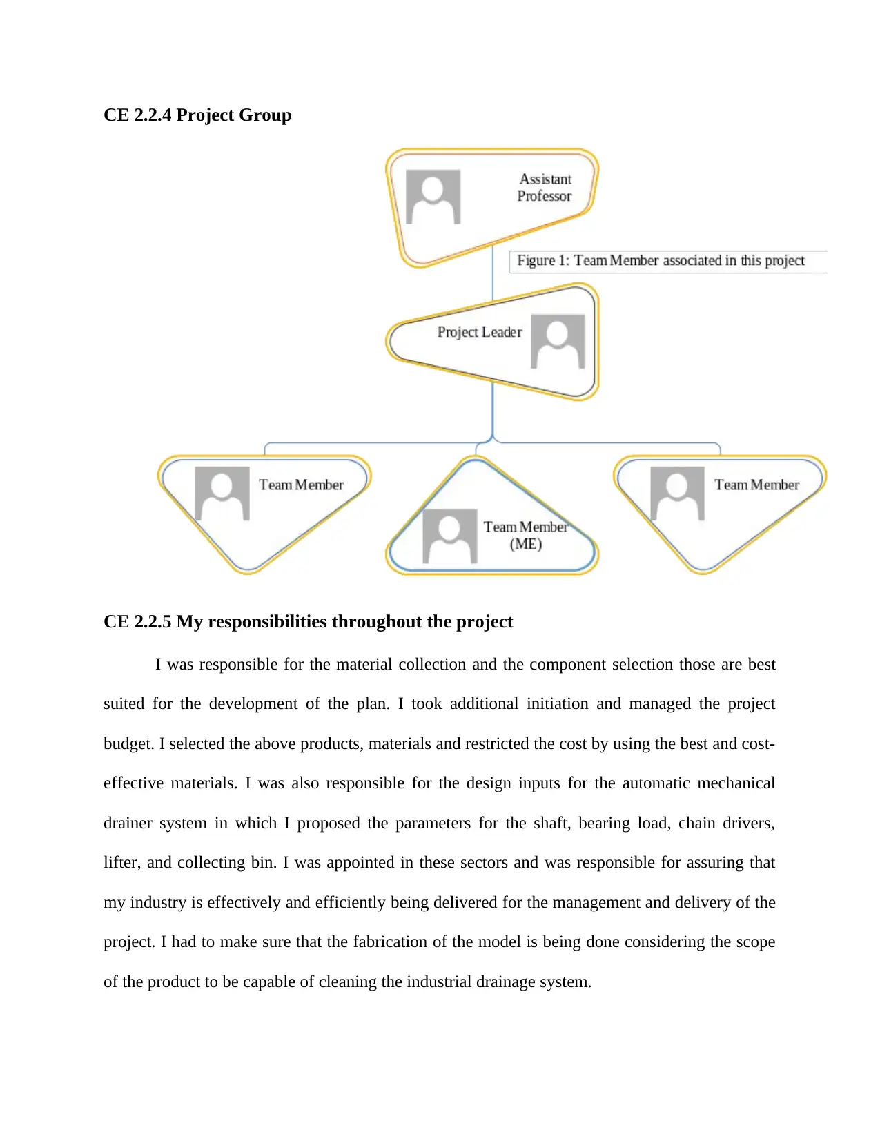
I was appointed as the team member and was working under the supervision of the
supervisor and the team leader. My role was as the mechanical engineer, and I have to deliver
my sector of jobs along with my initiations of the management. My primary work was to collect
and suggest the materials and components required for the project. I selected the elements those
could be capable of handling the impact of the various chemicals flowing through the drains and
make sure that the device is compatible in the long run competition.
Sl No. QUANTIT
Y
MATERIALS PARTS
a) 2 Mild steel Shaft
b) 4 Stainless steel Sprockets
c) 3 G.I Sheet Sheet metal
d) 9 Cast iron Iron bars
e) 1 Paint(silver) Paintwork
f) 4 Stainless steel Chain
g) 3 Mild steel and G.I Sheet Fabrication of lifter and box
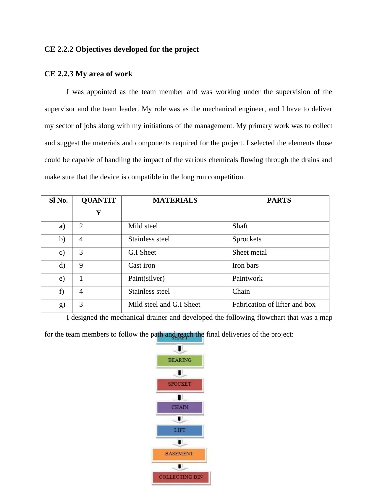
I designed the mechanical drainer and developed the following flowchart that was a map
for the team members to follow the path and reach the final deliveries of the project:
CE 2.2.4 Project Group
CE 2.2.5 My responsibilities throughout the project
I was responsible for the material collection and the component selection those are best
suited for the development of the plan. I took additional initiation and managed the project
budget. I selected the above products, materials and restricted the cost by using the best and cost-
effective materials. I was also responsible for the design inputs for the automatic mechanical
drainer system in which I proposed the parameters for the shaft, bearing load, chain drivers,
lifter, and collecting bin. I was appointed in these sectors and was responsible for assuring that
my industry is effectively and efficiently being delivered for the management and delivery of the
project. I had to make sure that the fabrication of the model is being done considering the scope
of the product to be capable of cleaning the industrial drainage system.
Secure Best Marks with AI Grader
Need help grading? Try our AI Grader for instant feedback on your assignments.
CE 2.3 Distinctive Activity
CE 2.3.1 Comprehending the theory of the project
I placed the device across the drain in a manner to restrict only water to flow through the
base designed for the product. The wastes such as bottles, plastic cans, and cover, etc. floating
through the drains will be lifted by lifters embedded in the product design that is ultimately
connected to the chain. I managed to set the string that can revolve with the sprocket wheel that
has been associated with the motor. I used electrical energy for allowing the motion in the
developed model that will allow the rotation in the lifter of the design in a manner to allow lifting
of the plan.
CE 2.3.2 Engineering knowledge and skills applied in the project
I calculated the design inputs for the entire project as mentioned below:
I identified that for the instances if the overall weight of the product exceeded more than its
estimated weight, then the bearing load will also be increasing that could lead to the improper
rotation of the chain occurs. So, I delivered the following calculation for determining the exact
parameters required for building the model of the project.
Shaft
Length = 910 mm
Outer Diameter=24mm
Inner Diameter = 21mm
Material used = Mild steel.
Length between shaft to shaft = 930mm
Power transmitted by the shaft = 108577.5105watt
Maximum Bearing Load
L/g = 248.256/9.81 = 25.3064 Kg
Chain Drives
Chain length = L= p = 2057.4 mm
P=11.372mm.
Lifter
Breadth =120mm
Length=610mm
Each lifters’ Gap has been kept to 700mm
Collecting Bin
Height = 340mm
Breadth = 610mm
Length = 920mm
Essentially, fabrication of the model the storm cellar part is set up by welding the metal
bars by electric welding. At that point, I welded the supporting bars at an edge of 90 degrees
from the storm cellar; the pad square heading is settled to the supporting bar and the front piece
of the cellar. Empty barrel-shaped shafts are settled to the course, and furthermore, chain drive is
additionally settled to the pole to settle the poles the factor of security of the chain is determined.
I settled the lifters to the chain by gas welding at an equivalent separation from each.
CE 2.3.3 Accomplishment and task performed
I fabricated the entire model of the project based on the materials selected and the
calculations made in the above section those could be represented in the following figure:
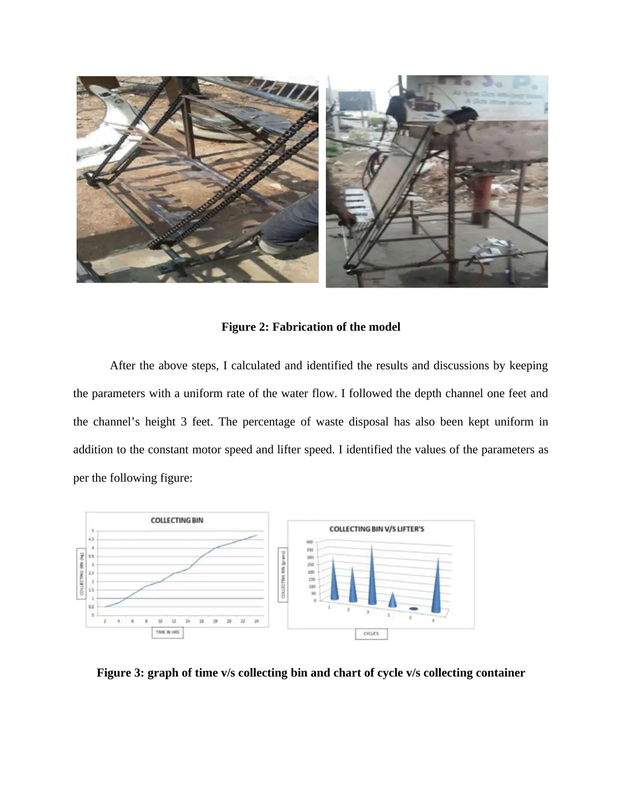
Figure 2: Fabrication of the model
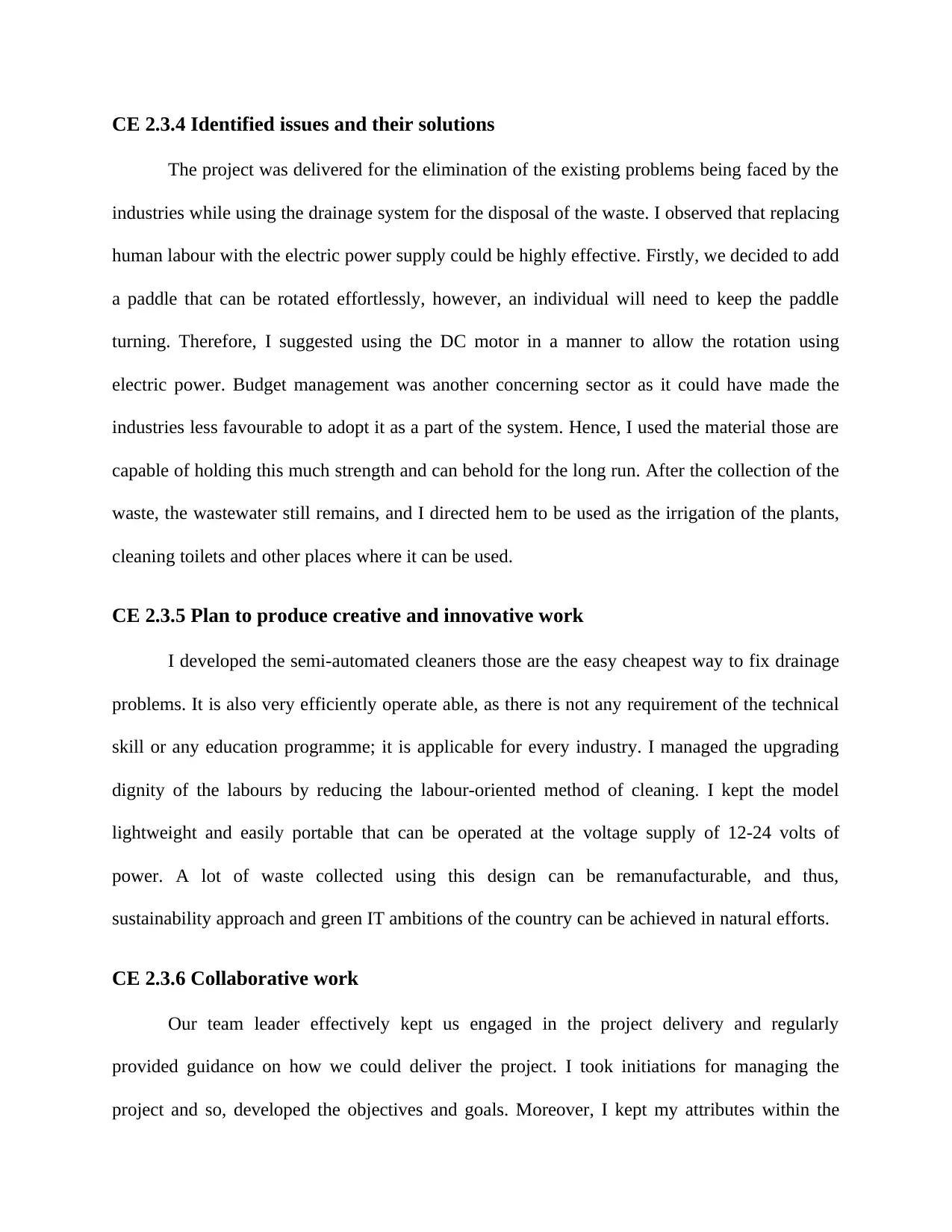
After the above steps, I calculated and identified the results and discussions by keeping
the parameters with a uniform rate of the water flow. I followed the depth channel one feet and
the channel’s height 3 feet. The percentage of waste disposal has also been kept uniform in
addition to the constant motor speed and lifter speed. I identified the values of the parameters as
per the following figure:
Figure 3: graph of time v/s collecting bin and chart of cycle v/s collecting container
Paraphrase This Document
Need a fresh take? Get an instant paraphrase of this document with our AI Paraphraser
CE 2.3.4 Identified issues and their solutions
The project was delivered for the elimination of the existing problems being faced by the
industries while using the drainage system for the disposal of the waste. I observed that replacing
human labour with the electric power supply could be highly effective. Firstly, we decided to add
a paddle that can be rotated effortlessly, however, an individual will need to keep the paddle
turning. Therefore, I suggested using the DC motor in a manner to allow the rotation using
electric power. Budget management was another concerning sector as it could have made the
industries less favourable to adopt it as a part of the system. Hence, I used the material those are
capable of holding this much strength and can behold for the long run. After the collection of the
waste, the wastewater still remains, and I directed hem to be used as the irrigation of the plants,
cleaning toilets and other places where it can be used.
CE 2.3.5 Plan to produce creative and innovative work
I developed the semi-automated cleaners those are the easy cheapest way to fix drainage
problems. It is also very efficiently operate able, as there is not any requirement of the technical
skill or any education programme; it is applicable for every industry. I managed the upgrading
dignity of the labours by reducing the labour-oriented method of cleaning. I kept the model
lightweight and easily portable that can be operated at the voltage supply of 12-24 volts of
power. A lot of waste collected using this design can be remanufacturable, and thus,
sustainability approach and green IT ambitions of the country can be achieved in natural efforts.
CE 2.3.6 Collaborative work
Our team leader effectively kept us engaged in the project delivery and regularly
provided guidance on how we could deliver the project. I took initiations for managing the
project and so, developed the objectives and goals. Moreover, I kept my attributes within the
project deliverables and led them to deliver within the estimated time and budget. I developed a
communication strategy and documentation of the projected growth that used to be updated in
every individuals' diary that helped us in improving the approach those could meet the project
deliverables within the estimated timeline and budget and deliver them accordingly.
CE 2.4 Project Review
I was able to deliver the project successfully, and the product was ready for the industrial
application where industries can use it for cleaning the drainages. I embedded the various
components after calculating the mathematical calculation of every element including the
variations that could influence the overall project. The proposed product can be used for the
national emission control for the industries and allow the enterprises to adopt the sustainability in
the much effective and easy way. I developed an efficient waste cleaning machine that can
automatically clean the sewage dirt with no additional labour efforts.
1 out of 9
Your All-in-One AI-Powered Toolkit for Academic Success.
+13062052269
info@desklib.com
Available 24*7 on WhatsApp / Email
![[object Object]](/_next/static/media/star-bottom.7253800d.svg)
Unlock your academic potential
© 2024 | Zucol Services PVT LTD | All rights reserved.

