PID Controller Simulation Report
VerifiedAdded on 2019/11/20
|14
|2002
|351
Report
AI Summary
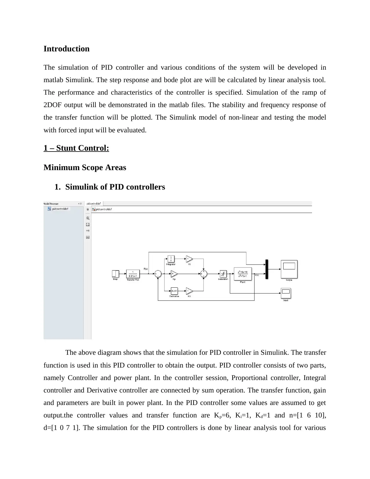
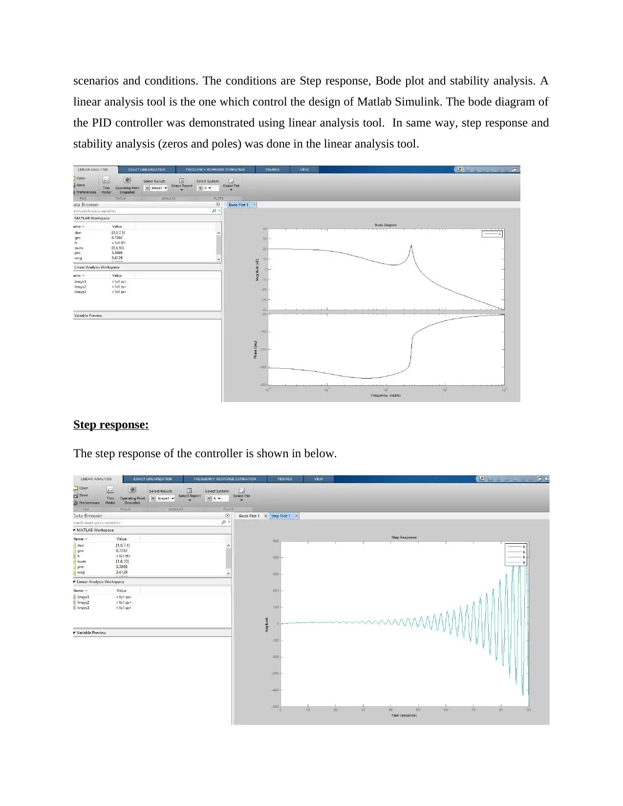
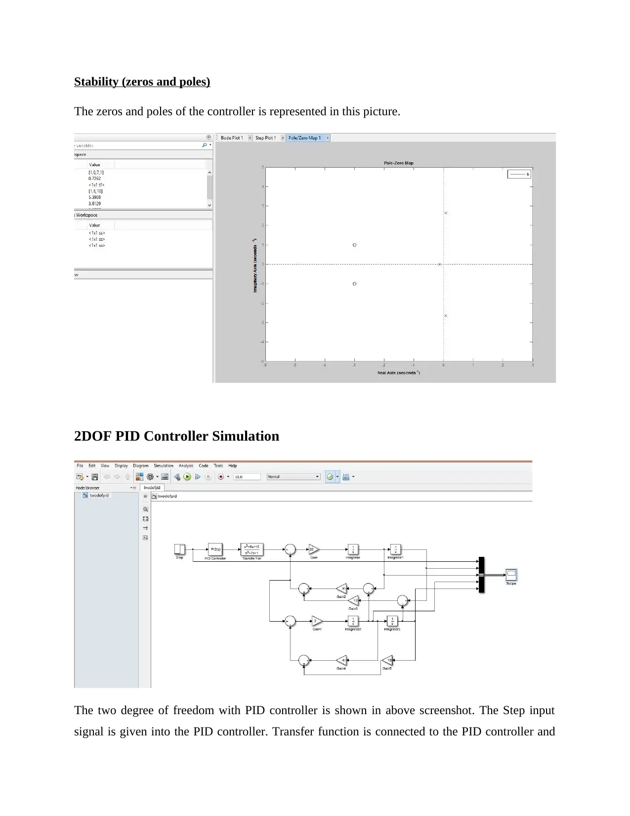
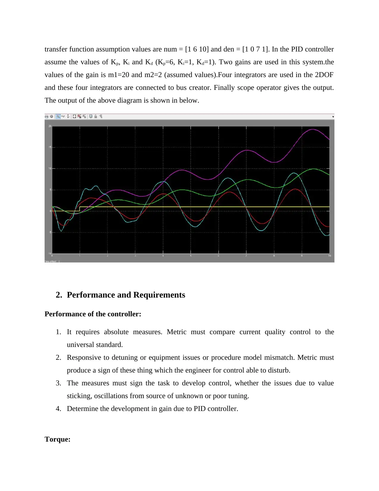
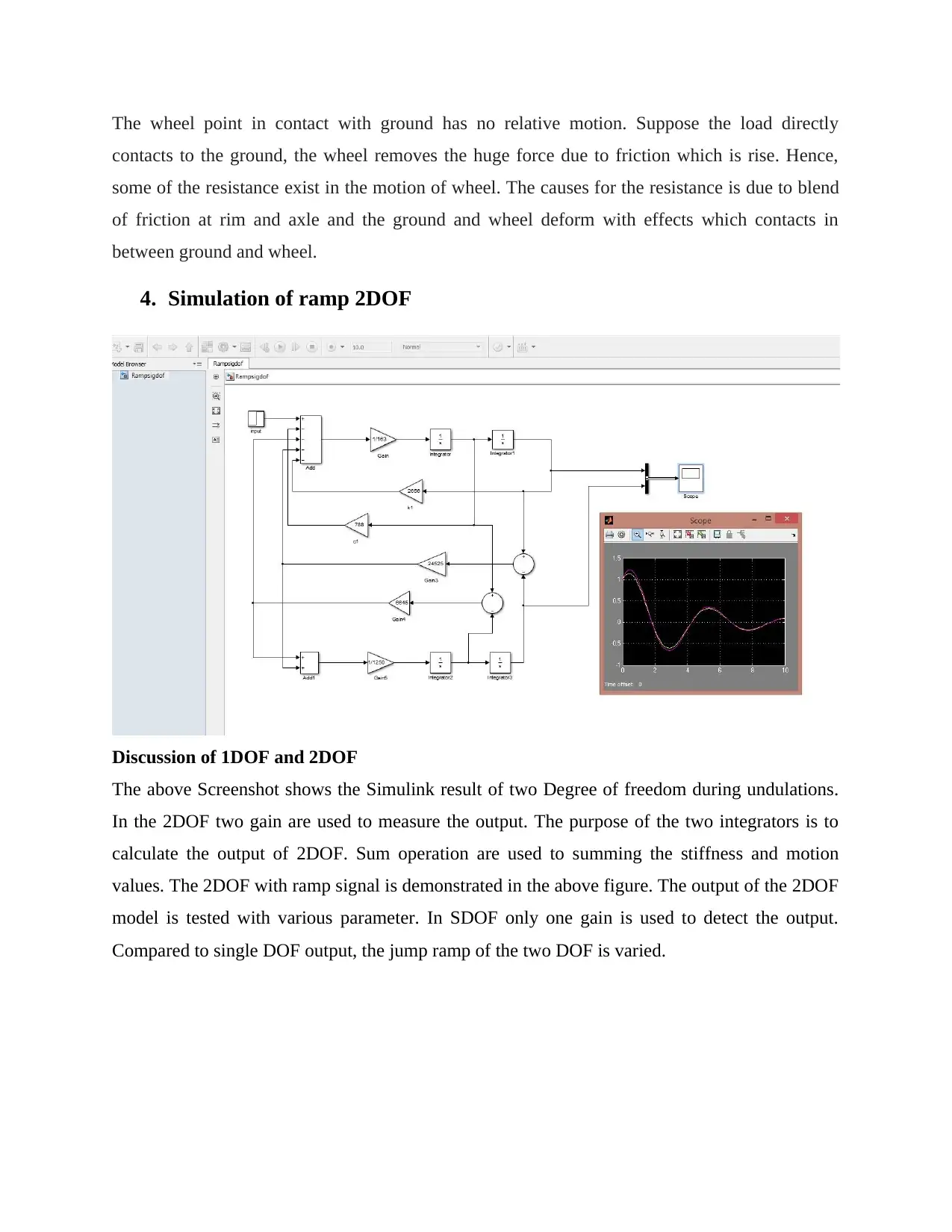
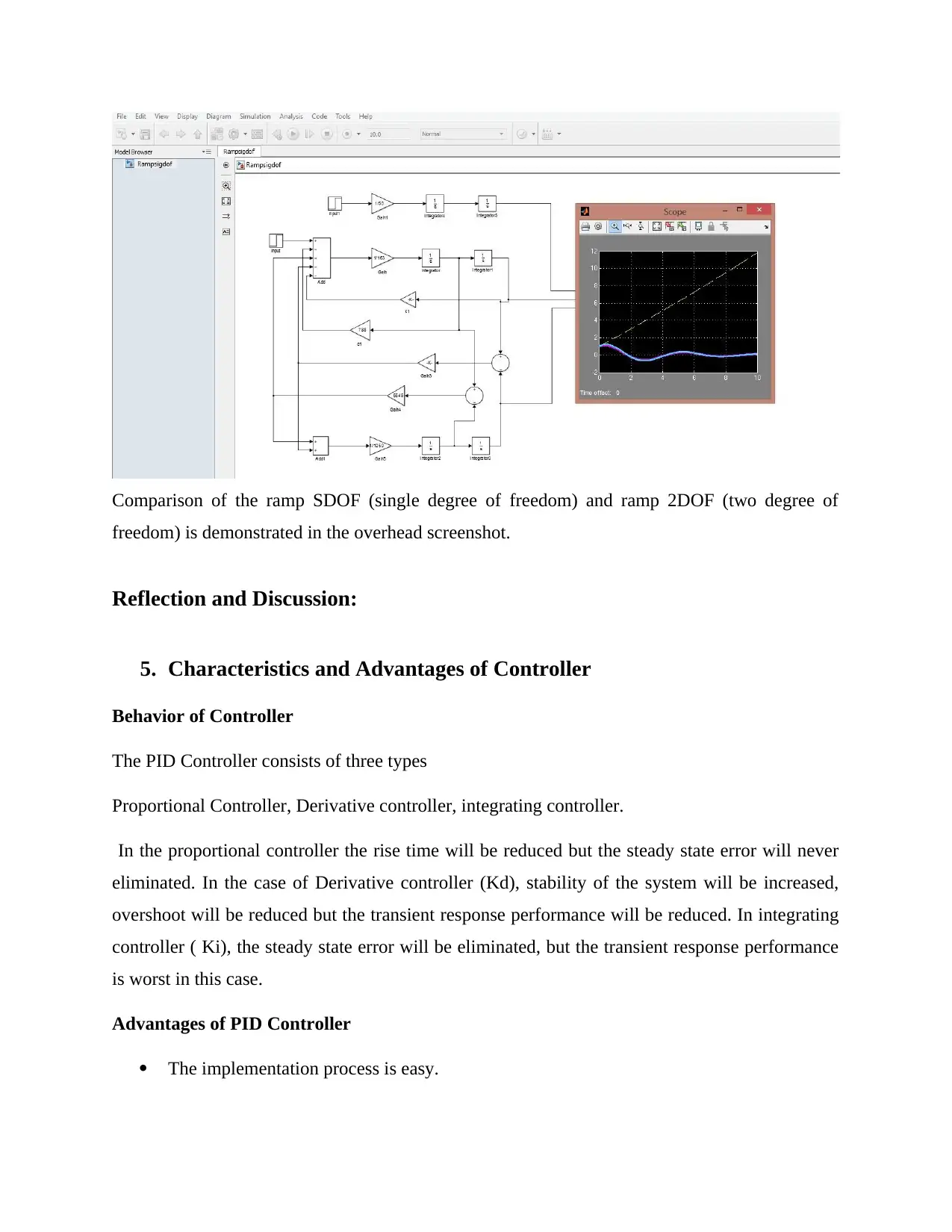
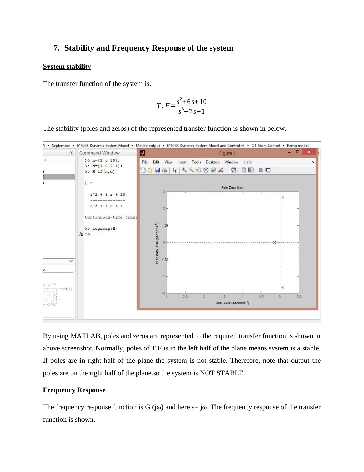
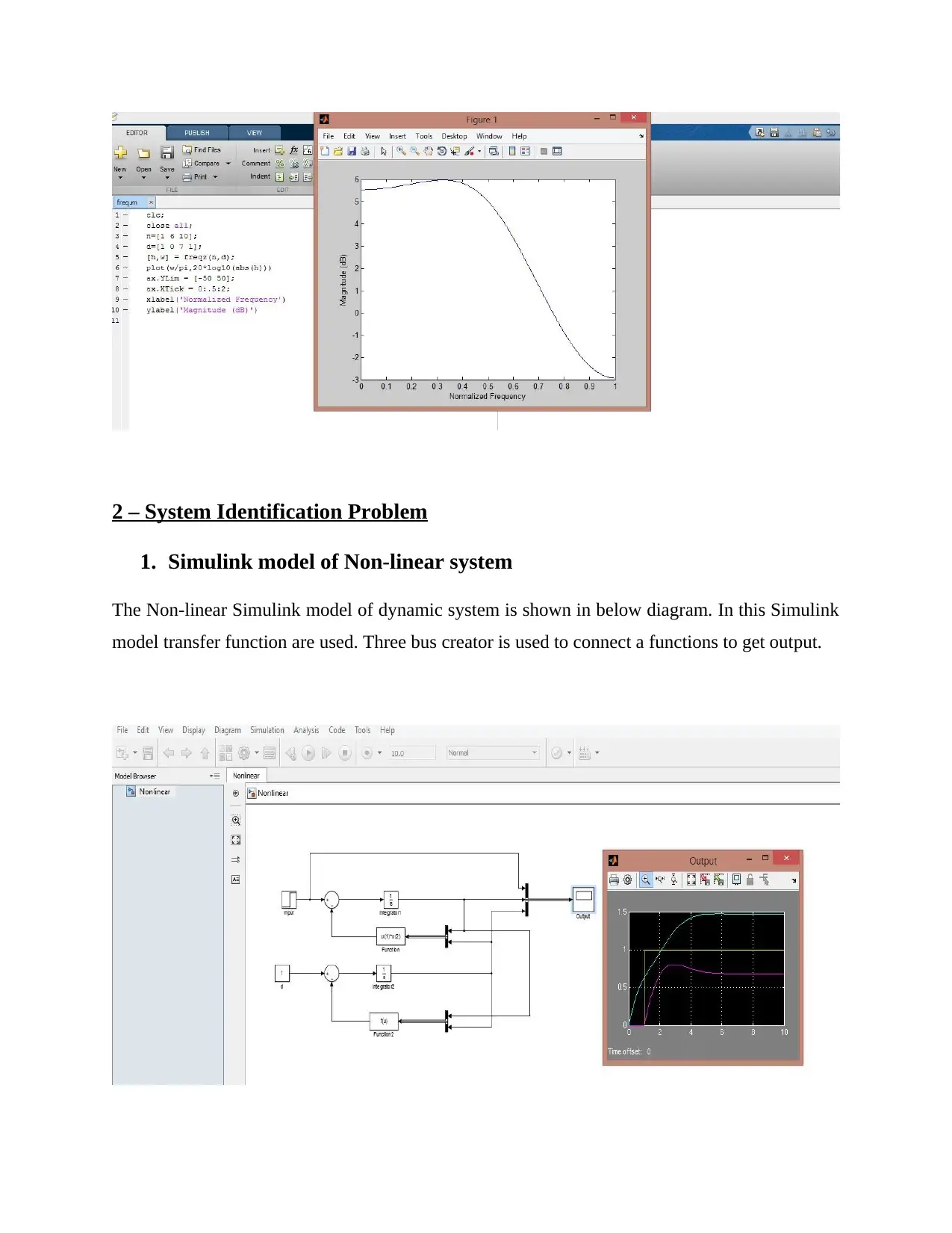
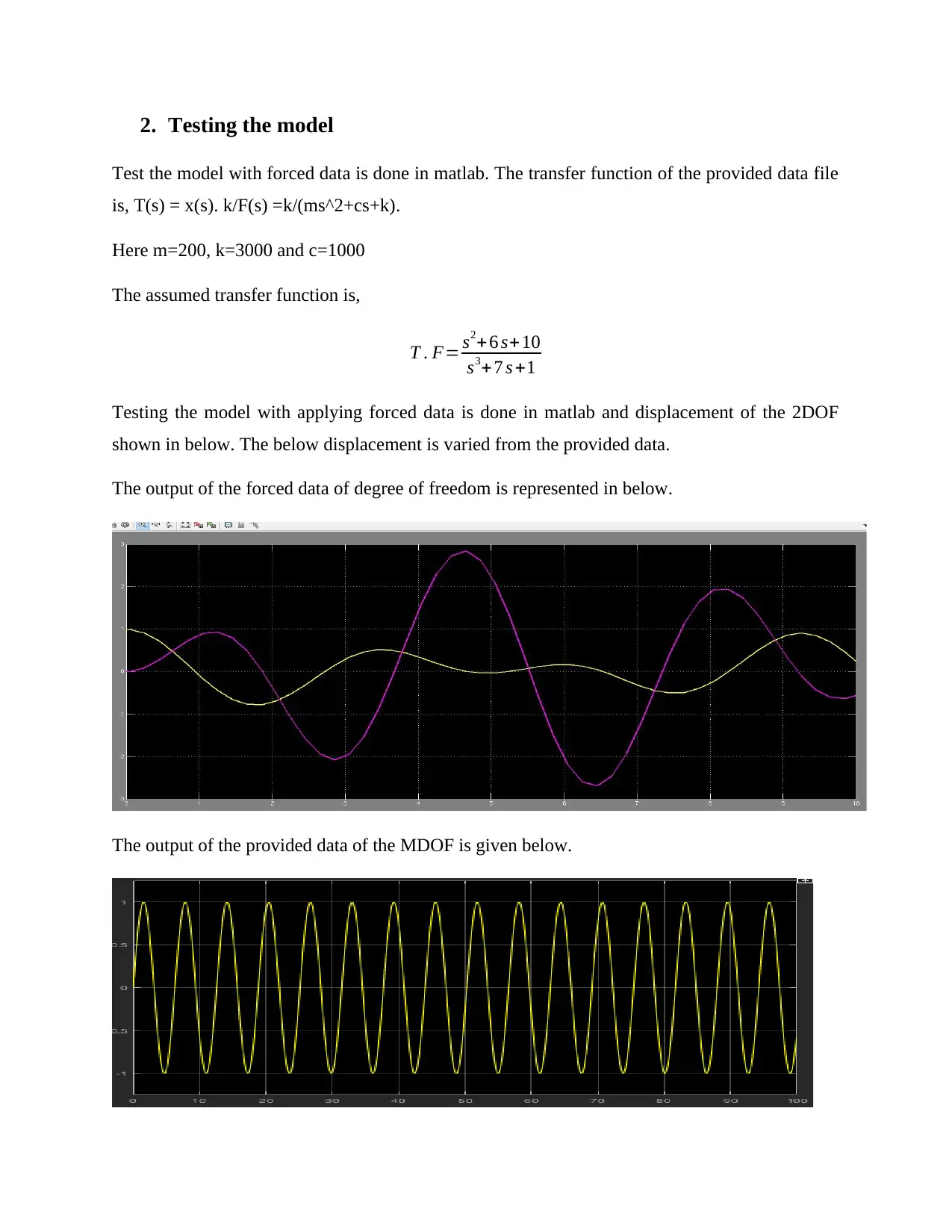
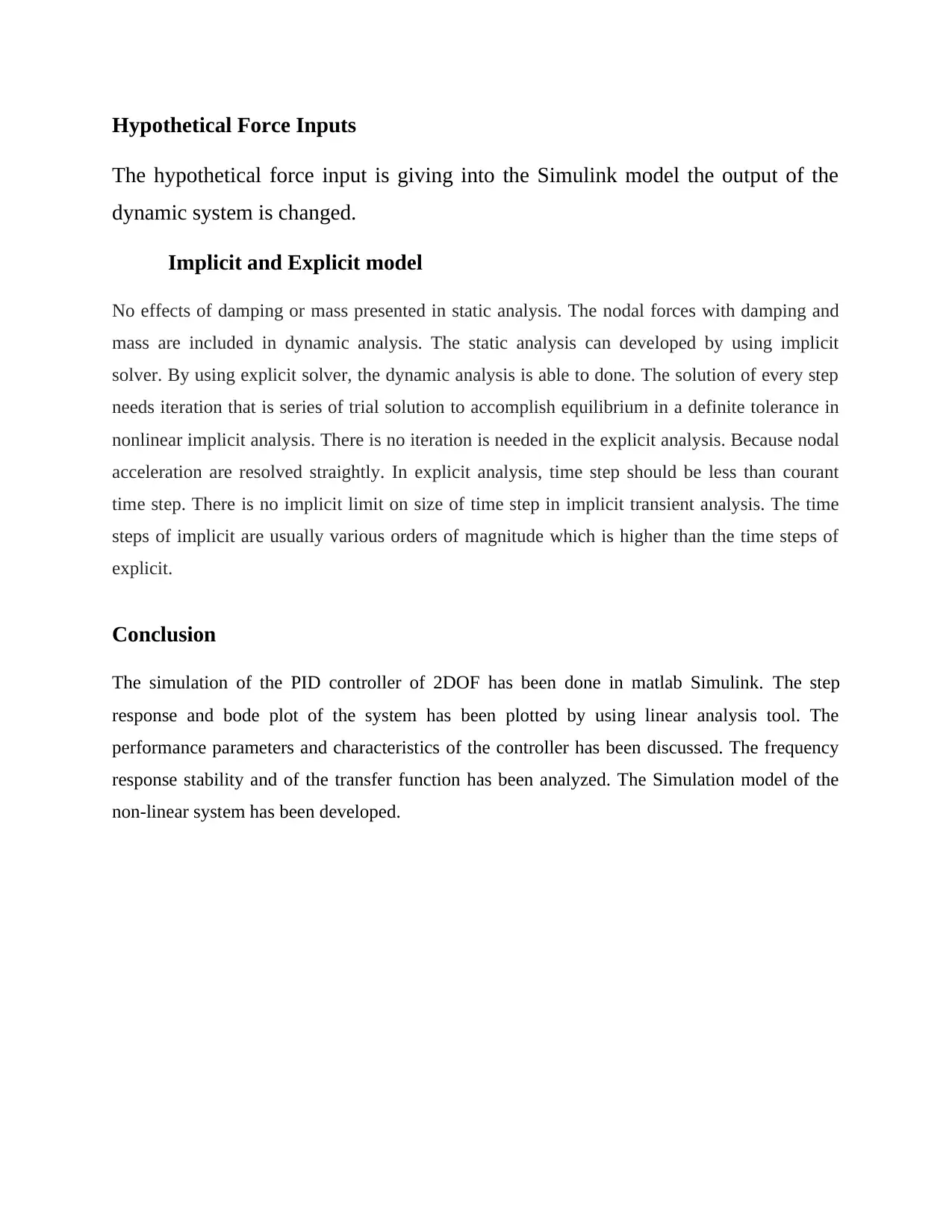
This report documents a comprehensive simulation of a PID controller and its various system conditions using MATLAB Simulink. The report begins with an introduction outlining the simulation's scope, which includes analyzing the step response and Bode plot using linear analysis tools, evaluating the controller's performance and characteristics, and simulating a ramp response for a 2DOF output. The stability and frequency response of the transfer function are also plotted and analyzed. The simulation extends to a non-linear system, testing the model with forced input. The report details the Simulink model of the PID controller, showing the connection of proportional, integral, and derivative controllers. It presents the step response, stability analysis (zeros and poles), and Bode plot obtained from the linear analysis tool. The simulation of a 2DOF PID controller is also described, including the use of two gains and four integrators. The report discusses performance requirements, including responsiveness to detuning and equipment issues. Concepts of torque and horsepower are explained in the context of the system. Ground wheel friction requirements are addressed. A comparison between 1DOF and 2DOF systems is provided, showing the Simulink results and discussing the differences in their ramp responses. The report concludes with a discussion of the characteristics and advantages of the PID controller, including its components (Kp, Ki, Kd), and assumptions made during the simulation. Finally, the stability and frequency response of the system are analyzed, and the Simulink model of the non-linear system is presented, along with the results of testing the model with forced data. The report concludes by summarizing the findings and includes references.
1 out of 14
Related Documents


Your All-in-One AI-Powered Toolkit for Academic Success.
+13062052269
info@desklib.com
Available 24*7 on WhatsApp / Email
![[object Object]](/_next/static/media/star-bottom.7253800d.svg)
Copyright © 2020–2026 A2Z Services. All Rights Reserved. Developed and managed by ZUCOL.