Mechanics Problems and Solutions

Verified

Added on  2019/12/18

|32
|3416
|392
Essay
AI Summary
The assignment content consists of three questions related to physics, specifically mechanics and oscillations. Question 1 calculates the work done on a mass, its kinetic energy, and the coefficient of friction given initial conditions. Question 2 deals with the angular acceleration of a wheel under various forces, including gravity and torque. Question 3 involves calculating the frequency, amplitude, maximum velocity, and required mass of an oscillating system using Hooke's law.

Contribute Materials

Your contribution can guide someone’s learning journey. Share your documents today.
Document Page
STATIC
ENGINEERING
SYSTEM

Secure Best Marks with AI Grader

Need help grading? Try our AI Grader for instant feedback on your assignments.
Document Page
TASK 1
Simple supported beams: Load bearing structure can be of any forms. They are mainly of
three types like axial loading, bending and torsional loading which are being discussed.
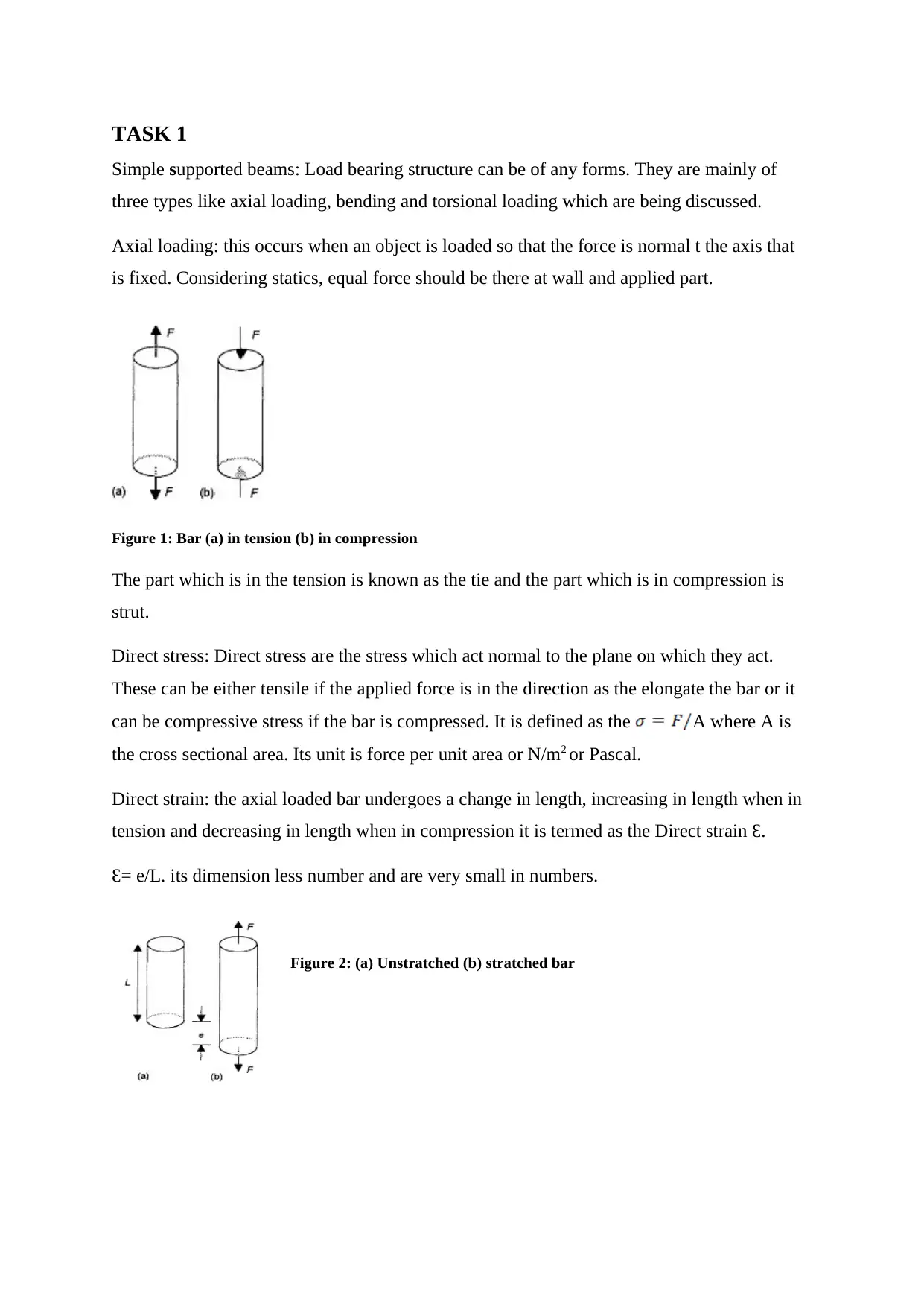
Axial loading: this occurs when an object is loaded so that the force is normal t the axis that
is fixed. Considering statics, equal force should be there at wall and applied part.
Figure 1: Bar (a) in tension (b) in compression
The part which is in the tension is known as the tie and the part which is in compression is
strut.
Direct stress: Direct stress are the stress which act normal to the plane on which they act.
These can be either tensile if the applied force is in the direction as the elongate the bar or it
can be compressive stress if the bar is compressed. It is defined as the A where A is
the cross sectional area. Its unit is force per unit area or N/m2 or Pascal.
Direct strain: the axial loaded bar undergoes a change in length, increasing in length when in
tension and decreasing in length when in compression it is termed as the Direct strain Ɛ.
Ɛ= e/L. its dimension less number and are very small in numbers.
Figure 2: (a) Unstratched (b) stratched bar
Document Page
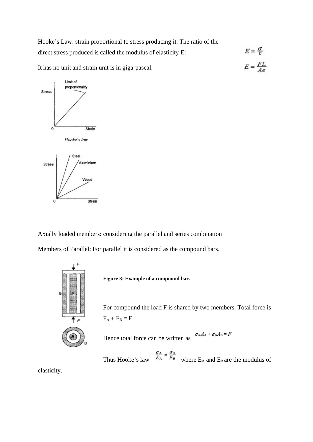
Hooke’s Law: strain proportional to stress producing it. The ratio of the
direct stress produced is called the modulus of elasticity E:
It has no unit and strain unit is in giga-pascal.
Axially loaded members: considering the parallel and series combination
Members of Parallel: For parallel it is considered as the compound bars.
Figure 3: Example of a compound bar.
For compound the load F is shared by two members. Total force is
FA + FB = F.
Hence total force can be written as
Thus Hooke’s law where EA and EB are the modulus of
elasticity.
Document Page
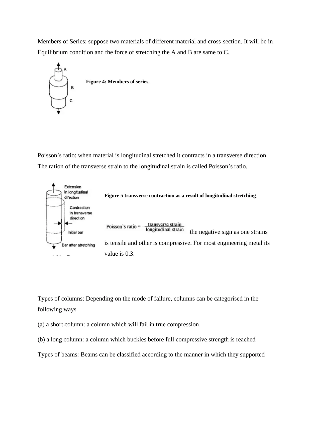
Members of Series: suppose two materials of different material and cross-section. It will be in
Equilibrium condition and the force of stretching the A and B are same to C.
Figure 4: Members of series.
Poisson’s ratio: when material is longitudinal stretched it contracts in a transverse direction.
The ration of the transverse strain to the longitudinal strain is called Poisson’s ratio.
Figure 5 transverse contraction as a result of longitudinal stretching
the negative sign as one strains
is tensile and other is compressive. For most engineering metal its
value is 0.3.
Types of columns: Depending on the mode of failure, columns can be categorised in the
following ways
(a) a short column: a column which will fail in true compression
(b) a long column: a column which buckles before full compressive strength is reached
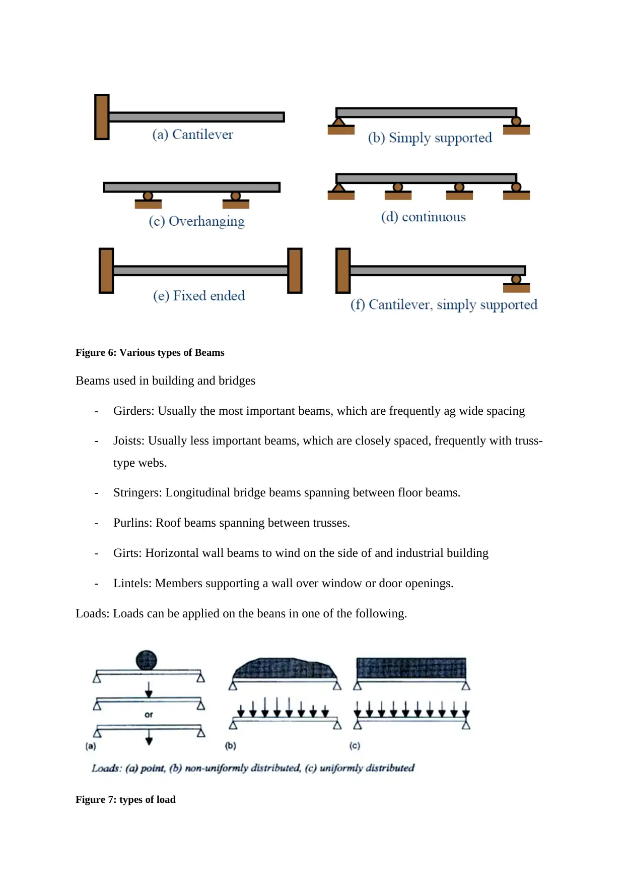
Types of beams: Beams can be classified according to the manner in which they supported

Secure Best Marks with AI Grader

Need help grading? Try our AI Grader for instant feedback on your assignments.
Document Page
Figure 6: Various types of Beams
Beams used in building and bridges
- Girders: Usually the most important beams, which are frequently ag wide spacing
- Joists: Usually less important beams, which are closely spaced, frequently with truss-
type webs.
- Stringers: Longitudinal bridge beams spanning between floor beams.
- Purlins: Roof beams spanning between trusses.
- Girts: Horizontal wall beams to wind on the side of and industrial building
- Lintels: Members supporting a wall over window or door openings.
Loads: Loads can be applied on the beans in one of the following.
Figure 7: types of load
Document Page
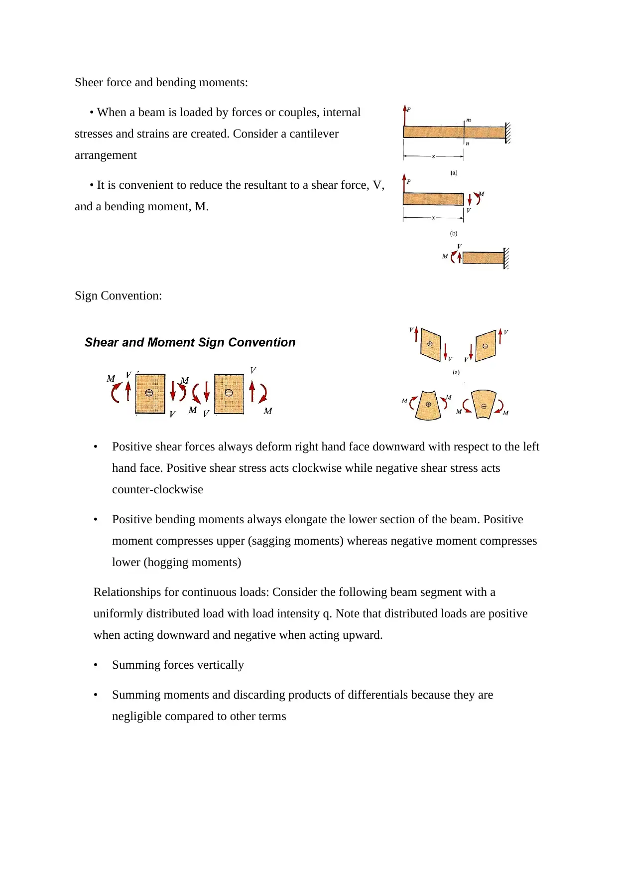
Sheer force and bending moments:
When a beam is loaded by forces or couples, internal
stresses and strains are created. Consider a cantilever
arrangement
It is convenient to reduce the resultant to a shear force, V,
and a bending moment, M.
Sign Convention:
Positive shear forces always deform right hand face downward with respect to the left
hand face. Positive shear stress acts clockwise while negative shear stress acts
counter-clockwise
Positive bending moments always elongate the lower section of the beam. Positive
moment compresses upper (sagging moments) whereas negative moment compresses
lower (hogging moments)
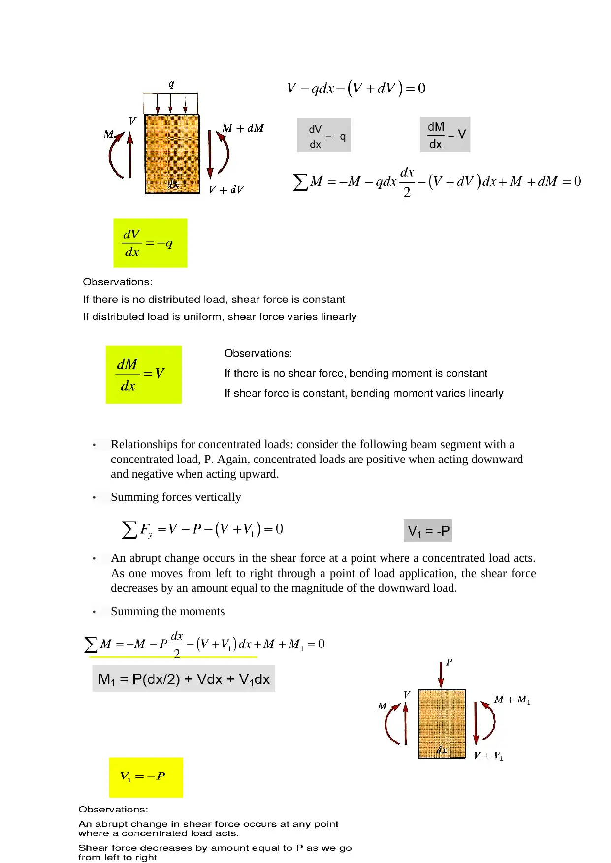
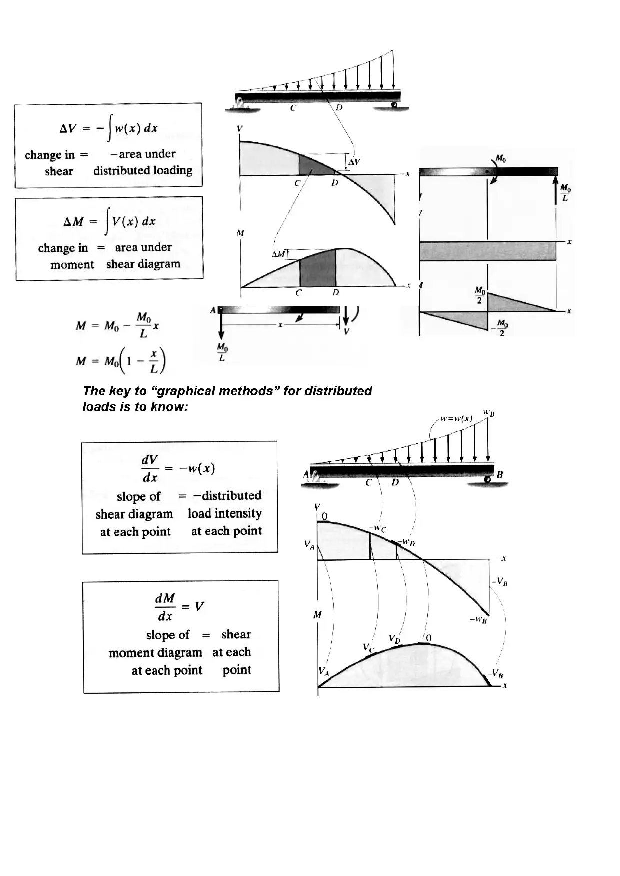
Relationships for continuous loads: Consider the following beam segment with a
uniformly distributed load with load intensity q. Note that distributed loads are positive
when acting downward and negative when acting upward.
Summing forces vertically
Summing moments and discarding products of differentials because they are
negligible compared to other terms
Document Page
Relationships for concentrated loads: consider the following beam segment with a
concentrated load, P. Again, concentrated loads are positive when acting downward
and negative when acting upward.
Summing forces vertically
An abrupt change occurs in the shear force at a point where a concentrated load acts.
As one moves from left to right through a point of load application, the shear force
decreases by an amount equal to the magnitude of the downward load.
Summing the moments

Paraphrase This Document

Need a fresh take? Get an instant paraphrase of this document with our AI Paraphraser
Document Page
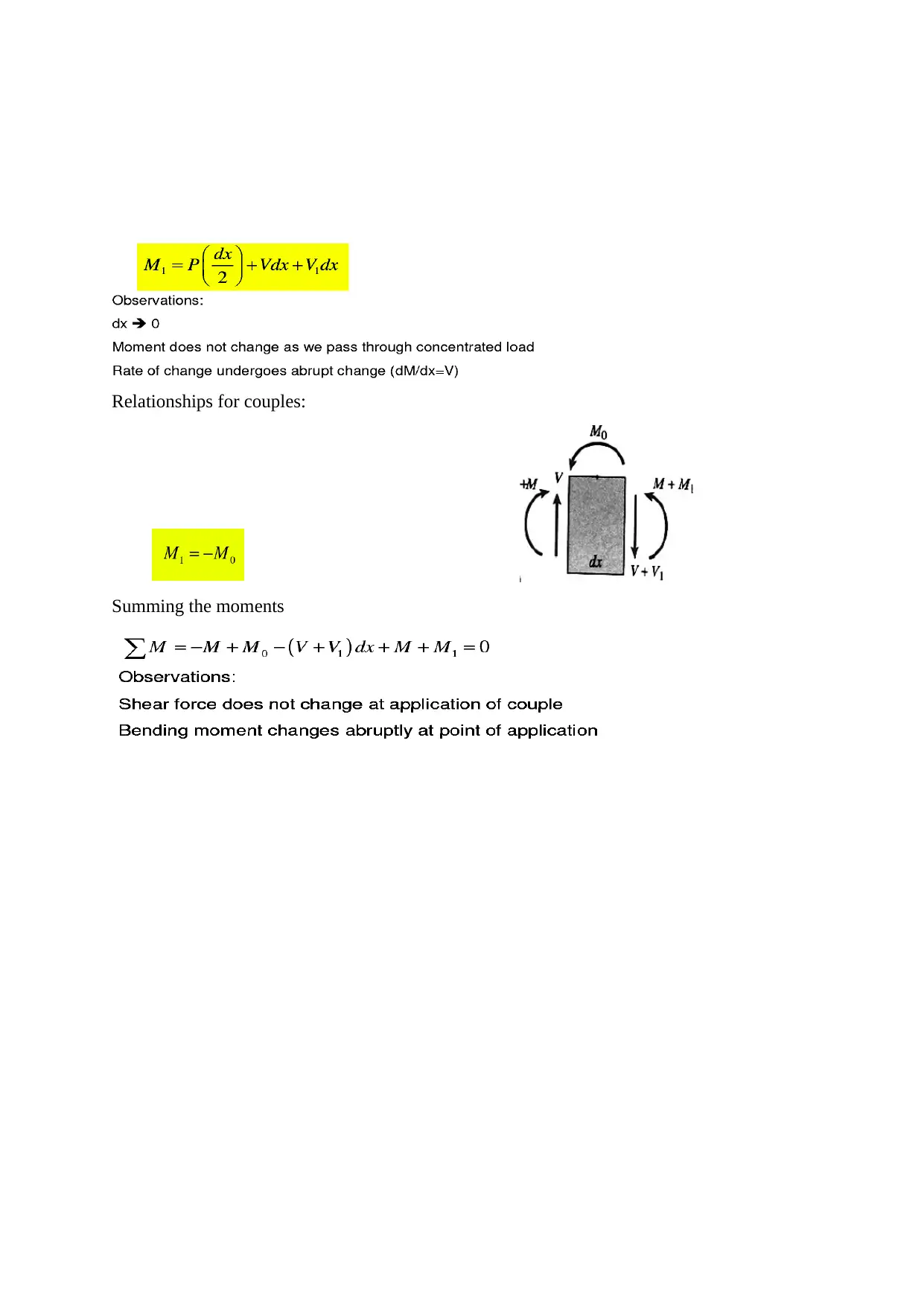
Relationships for couples:
Summing the moments
Document Page
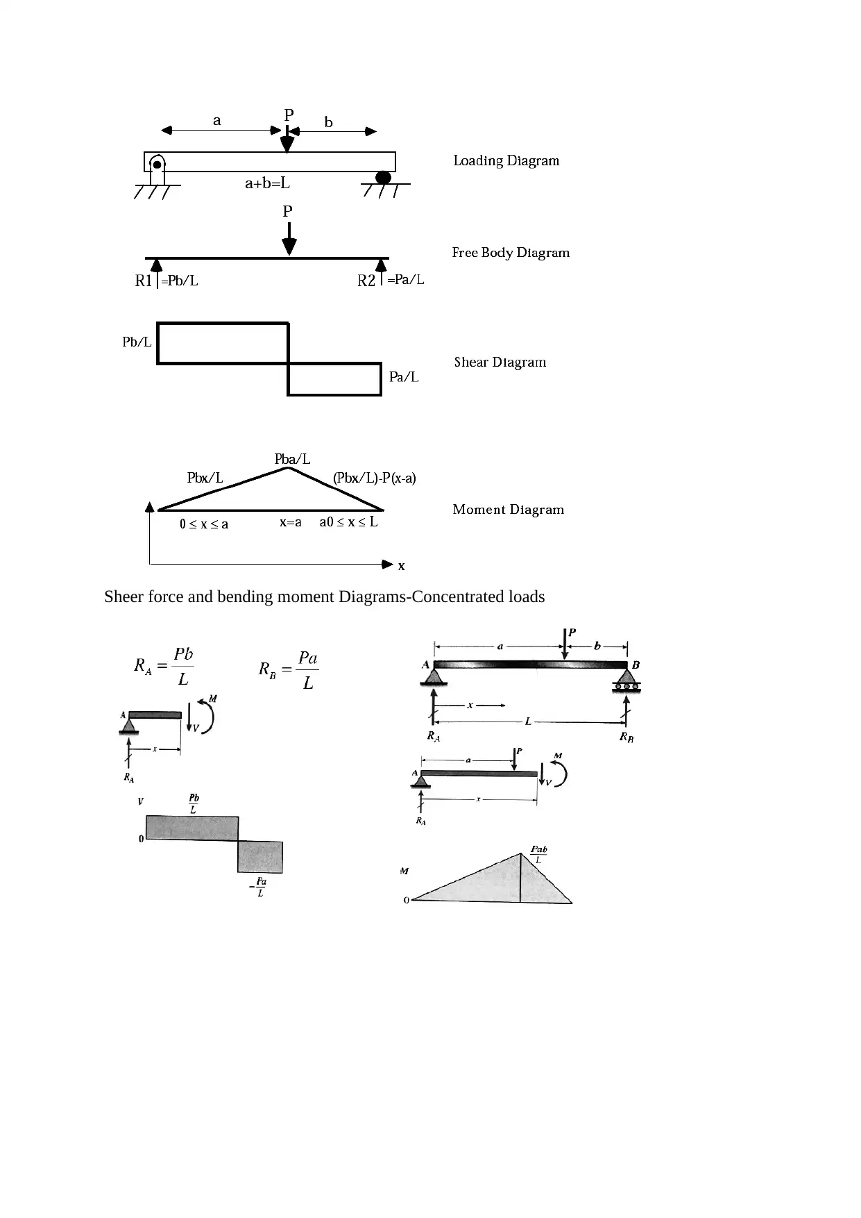
Sheer force and bending moment Diagrams-Concentrated loads
Document Page
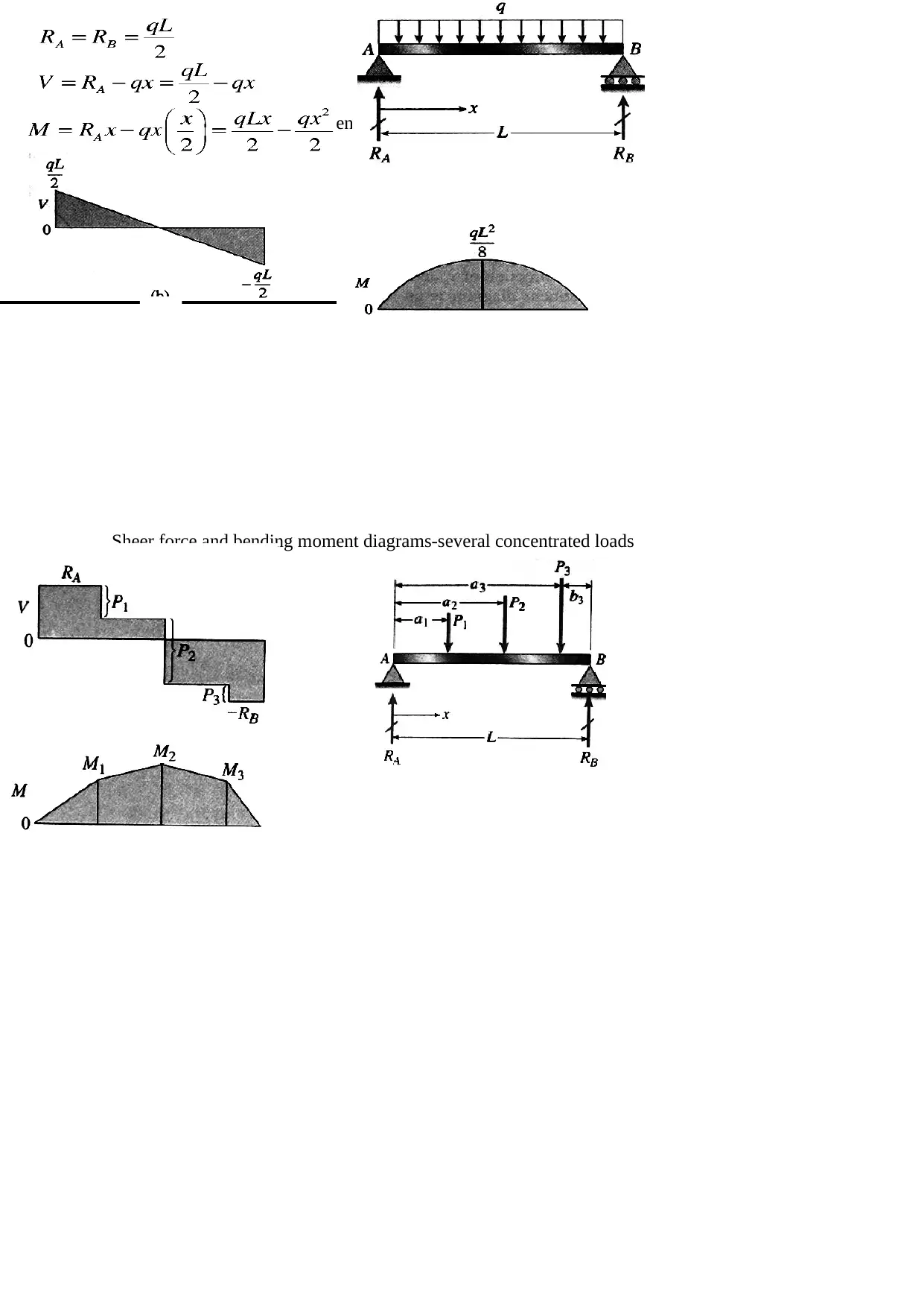
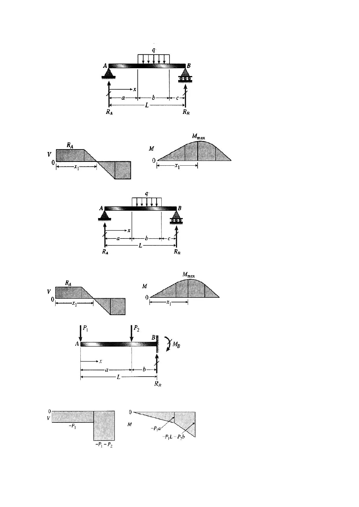
Sheer force and bending moment diagrams-Uniform loads
Sheer force and bending moment diagrams-several concentrated loads

Secure Best Marks with AI Grader

Need help grading? Try our AI Grader for instant feedback on your assignments.
Document Page
Document Page
Document Page
ELECTRICAL CIRCUITS

Paraphrase This Document

Need a fresh take? Get an instant paraphrase of this document with our AI Paraphraser
Document Page
11 Basic laws in circuit theory: voltage and current Kirchoff's laws, Tellegen’s theorem.
Real circuit and its mathematical model, Thevenin and Norton theorem.
1
1 Linear and non-linear passive components and active elements of analog circuits. The
basic principles, theorems and methods in the analysis of resistive circuits.
1
1 Circuits with harmonic currents in steady state - Method of complex numbers, phasor
diagrams. Coupled and resonant circuits.
1
1 Transients, analysis in time and frequency domain (Laplace transform). Two-ports
and their description using the matrices: Z, Y, H, A, etc., and S.
1
1 The concept of transfer function, amplitude and phase characteristics.
1
1 Basic concepts of circuits stability.
Electric Circuit
An electric circuit is an interconnection of electrical elements.
A circuit consists of a mesh of loops
Represented as branches and nodes in an undirected graph.
Circuit components reside in the branches
Connectivity resides in the nodes
Nodes represent wires
Wires represent equipotential
Charge
Document Page
Basic SI unit, measured in Coulombs (C)
Counts the number of electrons (or positive charges) present.
Charge of single electron is 1.602*10-19 C
One Coulomb = 6.24*1018 electrons.
Charge is always multiple of electron charge
Charge cannot be created or destroyed, only transferred.
Current
The movement of charge.
We always note the direction of the equivalent positive charges, even if the moving
charges are negative.
It is the time derivative of charge passing through a circuit branch
Unit is Ampere (A), is one Coulomb/second dt
dq
i
Customarily represented by i (AC) or I (DC).
Voltage
a difference in electric potential
always taken between two points.
It is a line integral of the force exerted by an electric field on a unit charge.
The SI unit is the Volt [V].
Power
Power is the product of voltage by current.
It is the time derivative of energy delivered to or extracted from a circuit branch.
Customarily represented by P or S or W.
The SI unit is the Watt [W].
AC vs. DC circuits
Direct Current (DC) is a current that remains constant with time is called
A common source of DC is a battery.
A current that varies sinusoidal with time is called Alternating Current (AC)
Mains power is an example of AC
Document Page
AC analysis
AC signal eg. voltage switches polarity over time. The signal graphed over time takes
on sine wave. The reason for such "shape" of the signal derives from the Faraday’s
Law of Electromagnetic Induction. We can describe the sine function both by sinus or
cosinus function:
Imax is the amplitude of the signal,
ω is angular frequency and is related to the physical frequency ω= 2πf,
φ is the phase angle in degrees or radians that the waveform has shifted either left or
right from the reference point.
The difference between sine or cosine wave is in the assumption of the time when the
phase is equal zero.
AC analysis
We can write the relationships between this two types of waveforms:
If in the circuit, there are two or more sources and all of them generates the same

Secure Best Marks with AI Grader

Need help grading? Try our AI Grader for instant feedback on your assignments.
Document Page
sinus or cosines function we do need make the above conversions. If some sources are
described by sine function, and some by cosine function we need to convert them all have
the same function. Because of power analysis the AC voltage is often expressed as a root
mean square (RMS) value, written as VRMS. For the sinusoidal waveform:
AC analysis
Considering two AC signals in the circuit e.g. two voltages or currents or voltage and
current, we can define the phase shift. It means that two or more waveforms are out of
step with each other. The amount of phase shift can be expressed in terms of degrees
or radians on the horizontal axis of the waveform the trigonometric sine function. A
leading waveform is defined as one waveform that is ahead of another. The waveform
which is behind is a lagging waveform.
AC circuit analysis must take into consideration both amplitude and phase shift of
voltage and current waveforms. This requires the use of a mathematical system called
complex numbers.
Basic theories and network analysis for AC circuit is analogous for AC and DC
circuits but using complex numbers to describe the signals. After considering the voltages
and currents in complex domain, we rewrite them to time domain.
Complex Numbers in AC analysis
Document Page
Phasor Diagram of a Sinusoidal Waveform
Analyzing the voltages and currents in the circuit, we describe them “frozen” at some
point in time. Then we can represent magnitude and direction by the vector (Phasor)
as a scaled line.
The positive rotation of the phase in phasor diagram is anti-clockwise rotation.
Then in the phasor diagram we can show the relation between currents and voltages in
phase and magnitude. Below there are some examples of the phasor diagram.
Phasor Diagram of a Sinusoidal Waveform
Document Page
Basic circuit elements – resistor
Resistors are circuit elements that resist the flow of current. When this is done a voltage
appears across the resistor's two wires.
A pure resistor turns electrical energy into heat. Devices similar to resistors turn this energy
into light, motion, heat, and other forms of energy.
Resistors don't care which leg is connected to positive or negative. We note the current flow
opposite to the voltage. This is called the an "positive charge sign convention. Some circuit
theory books assume "electron flow" flow sign convention.
Basic circuit elements – resistor
Resistance is measured in terms of units called "Ohms" (volts per ampere), which is
commonly abbreviated with the Greek letter Ω ("Omega"). Ohms are also used to measure
the quantities of impedance and reactance. The variable most commonly used to represent
resistance is "r" or "R". Resistance is defined as:

Paraphrase This Document

Need a fresh take? Get an instant paraphrase of this document with our AI Paraphraser
Document Page
where ρ is the resistivity of the material, L is the length of the resistor, and A is the cross-
sectional area of the resistor.
Conductance is the inverse of resistance. Conductance has units of "Siemens" (S). The
associated variable is "G":
r
G 1

Basic circuit elements – inductor
Inductance is the property whereby an inductor exhibits opposition to the change of current
flowing through it, measured in henrys (H).
The dependence between the current and the voltage of the inductor is described by
the equations:
The power stored by an inductor:
An inductor acts like a short circuit to dc (di/dt = 0) and its current cannot change abruptly.
Basic circuit elements – capacitor
Document Page
A capacitor is a passive element designed to store energy in its electric field.
A capacitor consists of two conducting plates separated by an insulator (or dielectric).
Capacitance C is the raBo of the charge q on one plate of a capacitor to the voltage
difference v between the two plates, measured in farads (F).
Where ε is the permittivity of the dielectric material between the plates, A is the surface area
of each plate, d is the distance between the plates.
The dependence between the charge and voltage is:
Then current –voltage relationship of the capacitor is described by the equations:
The power stored by an inductor:
A capacitor is an open circuit to dc (dv/dt = 0). And its voltage cannot change abruptly
(depends on integral of i).
Impedance of AC components
When talkingg about the AC circuits we talk about the impedance rather than
resistance. It is denoted as Z and compose of resistance R (the part from resistors)
and reactance X (the part from inductors and capacitors). The SI unit of impedance
is the Ohm (symbol ).
The inverse of impedance is admittance Y .
Similar to the impedance we can distinguish the real part conductance G and
imaginary part susceptance B. The SI unit of admittance is the Siemens (symbol S).
Document Page
We must remember that in the general case the inverse of resistance is different from
the conductance and the inverse of reactance is different from the susceptance.
AC resistor circuits
AC capacitor circuits

Secure Best Marks with AI Grader

Need help grading? Try our AI Grader for instant feedback on your assignments.
Document Page
AC inductor circuits
Document Page
Circuit Elements Ideal Independent Voltage Source
Document Page
provides a specified voltage or current that is completely independent of other circuit
variables
The voltage at the nodes is strictly defined by voltage of the source, the current flow
depends on the other elements in the circuit
The ideal voltage source is only a mathematical model.
Generally, we can divide the voltage sources into three groups:
Batteries
Generators
Supplies
Circuit Elements Ideal independent current source
The current flow in the branch is strictly defined by current of the source, the voltage at
the nodes of the source depends on the other elements in the circuit
The symbols used for AC current sources (similarly as for voltage sources) are the same as
for the DC current sources, but described with noncapital letters (e.g. j(t)).
The ideal current source similarly to ideal voltage source is only a mathematical model.
Circuit Elements dependent sources
Ideal dependent
voltage source
The voltage defined by the source depends on the voltage or current determined in this or
other circuit
Ideal dependent
current source
The current defined by the source depends on the voltage or current determined in this or
other circuit
The real voltage sources

Paraphrase This Document

Need a fresh take? Get an instant paraphrase of this document with our AI Paraphraser
Document Page
The real voltage source can be represented by ideal voltage source in series with resistance
Rs.
The real AC voltage source is represented by ideal voltage source in series with
impedance Zs. That impedance can have resistive, inductive or capacitive character.
Series-Parallel Connection
Typical circuits have some series connected components in some parts of the circuit and
parallel in others. Then it is impossible to apply a single set of rules to the all circuit. Instead,
it is possible to identify which parts of that circuit are series and which parts are parallel, then
selectively apply series and parallel rules.
Delta-Y conversions
In many applications circuits or fragments of circuits form a three-terminal network.
Components are then connected together in one of two ways: the “Delta,” or (also
known as the “Pi,” or ) configuration, and the “Y” (also known as the “T”)
configuration. The Delta (left side) and (right side) configuration take the form presented below:
Document Page
The Y (left side) and T (right side) configuration take the form presented below:
Document Page

Secure Best Marks with AI Grader

Need help grading? Try our AI Grader for instant feedback on your assignments.
Document Page
Question 1
Answer
a) t = 0.92s ; d= 5m; F= 80N; M= 6 kg; u(initial)= 0m/s
Work done = force* distance
W= 80*5 = 400J
Work done = mad
a= w/md
a= 400 /(6/5)
a= 13.33 m/s
V= u0+at
V= 0+ (13.33 * 0.92)= 12.266m/s
K.E. = .5 m* (v)^2
K.E.= 6*12.266*12.266*0.5 = 451.36J
b) Kineic eneregy of the mass against time
Document Page
c) Kinetic Energy of the mass against distance
d) Cofficient of friction
μ k = Fk / N . Here, F = Fk; N = mg
F= 80N
μ k = Fk/ mg, g= 9.8 m/s^2
μ k = 451.45/ (6* 9.8 ) = 7.6777
Question 2
Answer:
(a)
a = g[(2m/(M+2m)] v=s/d w=v/r T=mg[M/(M+2m)] I=mk2
a = g[(2m/(M+2m)] where m = 0.5kg, M = 3kg and g = 9.81m/sec2
a= 2.45m/sec2 where gravity = 9.81m/sec2
Angular velocity = linear velocity/radius = (0.5/1.5)/0.3 = 1 rad/sec
Therefore, angular acceleration = change in angular velocity/time = (1-0)/1.5 = 0.6 rad/sec2
b) angular acceleration of the wheel= torque/ inertia
torque= mgr
T= .5* 9.8* 0.212= 1.0388
I = mr^2= .5*0.212 = .106
Document Page
Angular velocity = linear velocity/radius = (0.5/1.5)/0.3 = 1 rad/sec
Therefore, angular acceleration = change in angular velocity/time = (1-0)/1.5 = 0.6 rad/sec2
(c)
Kinetic energy of mass against time
T, tension=mg[M/(M+2m)] = 3.78 N
(d)
Frictional torque = total torque - accelerating torque = in (TR - Tf)
Tnet = M(k^2)a = 3x(0.212^2)x(1.47) = 0.198 Nm
Tf = (0.198x0.3) - 3(0.212^2)x1.47 = -0.139Nm
Frictional torque= 0.198 + 0.139 = 0.337
Question 3:
Answer 3:
(a) F= 1 / (2π) x √(200/0.3) = 4.11Hz
(b) Angular Frequency using ω= √(200/0.3) = 25.82 rads -1
A = displacement
ω = Angular Frequency
k = Spring Stiffness
Vmax = A x ω = 0.258 m/s

Paraphrase This Document

Need a fresh take? Get an instant paraphrase of this document with our AI Paraphraser
Document Page
(c)Amax = ω2 x A = 6.67 m/s2
(d)Mass required: M = k / ω2 = 200 / 51.639777952 = 0.075 kg = 750e-3 Kg
1 out of 32
circle_padding
hide_on_mobile
zoom_out_icon
[object Object]

Your All-in-One AI-Powered Toolkit for Academic Success.

Available 24*7 on WhatsApp / Email

[object Object]